Note: Descriptions are shown in the official language in which they were submitted.
CA 02803152 2014-02-28
LOW-POWER WIRELESSLY-LINKED RFID TRACKING SYSTEM
CROSS REFERENCE TO RELATED APPLICATION
[0001] This application claims priority to U.S. Provisional Application
No.
61/357,047, filed June 21, 2010, and titled LOW-POWER WIRELESSLY-LINKED RFID
TRACKING SYSTEM, U.S. Provisional Application No. 61/433,948, filed January
18, 2011,
and titled LOW-POWER WIRELESSLY-LINKED RFID TRACKING SYSTEM, and U.S.
Provisional Application No. 61/434,798, filed January 20, 2011, and titled LOW-
POWER
WIRELESSLY-LINKED RFID TRACKING SYSTEM.
BACKGROUND
[0002] Keeping track of people and equipment in underground areas can be
complicated. Confined spaces and rock may interfere with communication
signals. Workers
in underground areas, such as mines or tunnels, face many environmental
hazards, including
potential cave-ins, gas leaks, and other harmful situations. Because
underground tunnel
networks may extend over a large area, rescuers searching for trapped workers
may have
difficulty locating trapped workers. Further, trapped workers may have
difficulty finding self-
rescue tools and supplies deployed throughout a tunnel network.
[0003] Some previous approaches to providing communication in underground
areas
include adding independent underground radio tracking networks in addition to
existing
underground radio communication networks. However, such approaches may not be
easily
extensible and may compete with other underground utilities for power, space,
etc.
Extending, upgrading, and maintaining underground utilities for such
independent radio
networks may further complicate existing underground communication systems.
1
CA 02803152 2012-12-18
WO 2011/163279 PCT/US2011/041311
SUMMARY
[0004] Accordingly, various embodiments are provided herein for a
wirelessly-linked
RFID tracking system configured for tracking a plurality of RFID tags. For
example, self-
contained, low-power wireles sly-linked RFID readers communicating with an
existing mine
radio network are provided to detect and transmit information received from a
plurality of
small size, easily carried RFID tags borne by underground workers or
underground
equipment. Such RFID tags may store information about the worker or the
equipment bearing
the RFID tag. The wirelessly-linked RFID readers may then transmit the tag
information of
various RFID tags to a local server, the local server providing notification
and/or alarm
information for the various RFID tags to system users. Further, various user
interface
modules are provided to permit such wirelessly-linked RFID tracking systems to
be
configured, monitored, and maintained by system users using local and/or
remote servers.
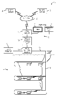
[0005] This Summary is provided to introduce a selection of concepts in a
simplified
form that are further described below in the Detailed Description. This
Summary is not
intended to identify key features or essential features of the claimed subject
matter, nor is it
intended to be used to limit the scope of the claimed subject matter.
Furthermore, the claimed
subject matter is not limited to implementations that solve any or all
disadvantages noted in
any part of this disclosure.
BRIEF DESCRIPTION OF THE DRAWINGS
[0006] FIG. 1 schematically shows an example operating environment for a
wirelessly-linked radio frequency identification (RFID) system in accordance
with an
embodiment of the present disclosure.
[0007] FIG. 2 schematically shows an example wireless RFID reader and
example
RFID transmitters in accordance with an embodiment of the present disclosure.
2
CA 02803152 2012-12-18
WO 2011/163279 PCT/US2011/041311
[0008] FIG. 3 schematically shows an example server computing device and
radio
network tracking headend interface unit in accordance with an embodiment of
the present
disclosure.
[0009] FIG. 4 schematically shows another example operating environment
for a
wirelessly-linked RFID system in accordance with an embodiment of the present
disclosure.
[0010] FIG. 5 schematically shows another example operating environment
for a
wirelessly-linked RFID system in accordance with an embodiment of the present
disclosure.
[0011] FIG. 6 schematically shows another example of a wireless RFID
reader and
example RFID transmitters in accordance with an embodiment of the present
disclosure. In
some examples, operation or reader to surface wireless data path uses mine
underground
radio network as the data highway. In other examples or in combination,
alternate operation
of wireless data connectivity from readers to surface is multi-hop mode, where
one reader
links to another out of the facility until connected to the server controller
on the surface.
[0012] FIG. 7 shows another example of a wireless RFID reader and an
example
RFID transmitter in accordance with an embodiment of the present disclosure.
[0013] FIG. 8 shows an example of a tracking headend interface unit in
accordance
with an embodiment of the present disclosure.
[0014] FIG. 9 shows an example login graphical user interface in
accordance with an
embodiment of the present disclosure.
[0015] FIG. 10 shows an example display of location and time information
in
accordance with an embodiment of the present disclosure.
[0016] FIG. 11 shows an example tag alert display and an example reader
alert
display in accordance with an embodiment of the present disclosure.
[0017] FIG. 12 shows an example communication alert display and an
example data
collection alert display in accordance with an embodiment of the present
disclosure.
3
CA 02803152 2012-12-18
WO 2011/163279 PCT/US2011/041311
[0018] FIG. 13 shows an example graphical map view in accordance with an
embodiment of the present disclosure.
[0019] FIG. 14 shows another example graphical map view in accordance
with an
embodiment of the present disclosure.
[0020] FIG. 15 shows an example search utility graphical user interface
in accordance
with an embodiment of the present disclosure.
[0021] FIG. 16 shows an example search results display in accordance with
an
embodiment of the present disclosure.
[0022] FIG. 17 shows an example history display in accordance with an
embodiment
of the present disclosure.
[0023] FIG. 18 shows an example asset tag management graphical user
interface in
accordance with an embodiment of the present disclosure.
[0024] FIG. 19 shows an example asset addition graphical user interface
in
accordance with an embodiment of the present disclosure.
[0025] FIG. 20 shows an example asset editor graphical user interface in
accordance
with an embodiment of the present disclosure.
[0026] FIG. 21 shows an example reader management graphical user
interface in
accordance with an embodiment of the present disclosure.
[0027] FIG. 22 shows an example emergency evacuation alarm graphical user
interface in accordance with an embodiment of the present disclosure.
[0028] FIG. 23 schematically shows an example mine radio network that may
be used
with a wirelessly-linked RFID system in accordance with an embodiment of the
present
disclosure.
4
CA 02803152 2012-12-18
WO 2011/163279 PCT/US2011/041311
[0029] FIG. 24 schematically shows example connections between an example
tracking headend interface unit and an example mine radio network headend in
accordance
with an embodiment of the present disclosure.
[0030] FIG. 25 schematically shows an example DC powered wirelessly-
linked RFID
reader in accordance with an embodiment of the present disclosure.
[0031] FIG. 26 schematically shows an example battery powered wirelessly-
linked
RFID reader in accordance with an embodiment of the present disclosure.
[0032] FIG. 27 schematically shows an example DC powered wirelessly-
linked RFID
reader including a battery backup in accordance with an embodiment of the
present
disclosure.
[0033] FIG. 28 shows an example wirelessly-linked RFID reader including
an
indicator light in accordance with an embodiment of the present disclosure.
[0034] FIG. 29 shows an example flowchart for a method of tracking an
RFID tag,
polling the RFID reader and receiving tag data in accordance with an
embodiment of the
present disclosure.
[0035] FIG. 30 shows a non-limiting example inby operating environment
for a
wirelessly-linked RFID system in accordance with an embodiment of the present
disclosure.
[0036] FIG. 31 schematically shows an example wireless RFID reader and
example
RFID transmitters in accordance with an embodiment of the present disclosure.
[0037] FIG. 32 schematically shows another example of a wireless RFID
reader and
example RFID transmitters in accordance with an embodiment of the present
disclosure.
[0038] FIG. 33A shows another example of a wireless RFID reader in
accordance
with an embodiment of the present disclosure.
[0039] FIG. 33B shows a bottom view of the example wireless RFID reader
of FIG.
33A.
CA 02803152 2012-12-18
WO 2011/163279 PCT/US2011/041311
[0040] FIG. 33C shows another side view of the example wireless RFID
reader of
FIG. 33A.
[0041] FIG. 33D illustrates an exploded view of another example wireless
RFID
reader.
[0042] FIG. 34 shows a perspective view of an example wireless RFID
reader in
accordance with an embodiment of the present disclosure.
[0043] FIG. 35 schematically shows an example configuration of an example
RFID
reader and environmental sensors in accordance with an embodiment of the
present
disclosure.
[0044] FIG. 36A schematically shows another example configuration of an
example
gas card/board for the RFID reader in accordance with an embodiment of the
present
disclosure.
[0045] FIG. 36B schematically shows another example gas card/board for
the RFID
reader of FIG. 36A in a reduced power configuration in accordance with an
embodiment of
the present disclosure.
[0046] FIG. 36C schematically shows an example main reader board that may
be
included with an example RFID reader in accordance with an embodiment of the
present
disclosure.
[0047] FIG. 36D schematically shows an example expansion board that may
be
included with an example RFID reader in accordance with an embodiment of the
present
disclosure.
6
CA 02803152 2012-12-18
WO 2011/163279 PCT/US2011/041311
DETAILED DESCRIPTION
[0048] One approach to providing underground tracking and communication
is with a
wirelessly-linked radio frequency identification (RFID) system. For example, a
wirelessly-
linked RFID tracking system may include a wirelessly-linked RFID reader, which
may have
an all-wireless reader/radio capability. The wirelessly-linked RFID reader may
collect tag
information from a plurality of RFID tags as they pass within range of an RFID
antenna or an
RFID antenna system of the wirelessly-linked RFID reader.
[0049] The wirelessly-linked RFID reader may add time and location
information to
the tag information, and may store the tag information for wireless
transmission to an existing
mine radio network (which may be a two-way radio network). In this way,
wirelessly-linked
RFID readers are communicatively linked with the existing mine radio network
so as to
create a data path from an underground environment to a surface environment,
for example.
In some embodiments, tag information may be generated and/or transmitted in
real time. In
other example embodiments, tag information may be generated and/or transmitted
in
response to a polling command or via other bursting transmission methods. As
an example, a
tag reception timer may be integral with the reader unit. Further, it should
be appreciated that
the tag reception timer may be synchronized to the master computer clock on
the surface for
accuracy.
[0050] The wireles sly-linked RFID readers may be physically independent
of the
mine radio network. For example, some embodiments of the wireles sly-linked
RFID readers
may be self-contained, so that no hard-wired connections to the mine radio
network are
required. This configuration is referred to as multi-hop and is described in
more detail herein.
Further, in some embodiments, a wireles sly-linked RFID reader may be located
hundreds of
feet from the mine radio network while still providing wireless data
connectivity. Further
still, in some examples, a single wirelessly-linked RFID reader may have a
plurality of RFID
7
CA 02803152 2012-12-18
WO 2011/163279 PCT/US2011/041311
receivers (and reverse transmitters, if activated) (such as an RFID input
port) to create a
plurality of distinct RFID tag reception zones for receiving tag information
from various
RFID tags.
[0051] Tag information transmitted from the wirelessly-linked RFID
readers may be
received at one or more local servers for coordinating and operating the
wirelessly-linked
RFID tracking system. Such local servers may be used to program or update the
wirelessly-
linked RFID readers. In some embodiments, a tracking headend interface unit
may facilitate
an interface between the mine radio network and the local server. For example,
in some
embodiments, a connection between a Tracking Head Unit and the server computer
may be
accomplished via a serial or USB (universal serial port) where the server is
local to the head
unit. In some embodiments, such connections may be extended using Internet
protocol (IP)
to Serial interface converters, RS-232 to RS-485 converters, or other suitable
wireless link
schemes where the server is remotely located from the head unit. Other example
embodiments are discussed in more detail below.
[0052] Some examples of the wirelessly-linked RFID tracking system may be
configured to use one or more frequencies in a land mobile radio band which
may have a
frequency range of approximately 144-950 MHz, which may permit the wirelessly-
linked
RFID tracking system to operate using an existing or new commercial two-way
underground
mine radio network. This may provide ready deployment and extensibility of the
wireles sly-
linked RFID tracking system.
[0053] Aspects of this disclosure will now be described by example and
with
reference to the illustrated embodiments. Components and other elements that
may be
substantially the same in one or more embodiments are identified coordinately
and are
described with minimal repetition. It will be noted, however, that elements
identified
coordinately may also differ to some degree. Furthermore, the size, shape,
and/or
8
CA 02803152 2012-12-18
WO 2011/163279 PCT/US2011/041311
configurations of the various components of the wirelessly-linked RFID
tracking system are
provided to ease understanding and are not intended to be technically precise.
[0054] FIG. 1 schematically shows an example operating environment for a
wirelessly-linked RFID tracking system 100. In one example, mine workers
working in
different areas of mine 102 may be tracked as they go about their work.
Wirelessly-linked
RFID tracking system 100 may track location information for the workers, time
information
for the workers, etc. during the course of a shift.
[0055] The RFID tracking system is further illustrated in FIGS. 2-5 which
should be
referenced in combination with FIG 1. In this regard, the FIG. 2 schematically
shows an
example wireless RFID reader and example RFID transmitters and FIG. 3
schematically
shows an example server computing device and radio network tracking headend
interface unit
for use in the RFID tracking system. For further illustrative purposes, FIGS.
4-5 show
example embodiments of wirelessly-linked RFID tracking systems in operation.
[0056] To further appreciate system 100, attention is directed to FIG. 29
which shows
an example flowchart for a method 2900 for use with the RFID tracking system.
The method
provides a flowchart of using the RFID tacking system for tracking personnel
and/or
equipment bearing an RFID tag using an embodiment of a wireles sly-linked RFID
tracking
system. Method 2900 may be employed after deploying a plurality of wireles sly-
linked
RFID readers in communication with a mine radio network, within an underground
environment, for example. At 2902, a user (e.g., a miner) wearing an RFID tag
enters a
receiving zone of an RFID reader. At 2904, the RFID reader receives a first
message from the
RFID tag, the first message including data stored at the RFID tag, also
referred to as tag data.
[0057] At 2906, the RFID reader is polled by the server for current
buffer load. The
reader is thus, in some examples, polled directly via the underground radio
network, or
9
CA 02803152 2012-12-18
WO 2011/163279 PCT/US2011/041311
optionally, indirectly via an adjacent wireless reader and requests a send
from the polled unit.
In this way, tag data may be sent as a message to the server.
[0058] For example, the polled reader may transmit a second message back
to the
local server via an existing mine radio network and/or an interconnecting
reader. The second
message may include at least a portion of the data received from the first
message. The
second message may include additional information. For example, the second
message may
include a time, and/or location corresponding to the receipt of the first
message; however, it
will be appreciated that the second message may include other information,
e.g. atmospheric
monitoring data. In this way, the tag may provide a unique identifier where
time and location
is appended to the tag ID in the reader. It is noted that in some systems the
reader time is
synchronized to computer time as part of the initial server boot up such that
there is time
accuracy. It should be appreciated that the above examples are provided as non-
limiting
examples. Further, in some examples, the tag data is checksummed to verify and
check the
validity of the data for security purposes. The reader data buffer may be
cleared after the
polling and checksum of the data.
[0059] At 2908, the local server receives the second message, and at
2910, the local
server compares RFID tag identification information to a manifest. At 2912,
the local server
displays a location of the miner, either in tables, such as indicated at 150
in FIG. 1 and/or in a
graphic view 152. The displays may include a mine map overlay, such that the
graphic
indicates in a map form the position and location of the RFID tag and thus the
miner and/or
equipment with the RFID tag. Time data may be also stored and displayed. The
incoming
data posts to a database in the server and may be queued to populate tables
and/or graphics.
[0060] Referring against to FIG. 29, it will be appreciated that method
2900 is
provided by way of example and may include additional or alternative steps
than those shown
in FIG. 29. Further, it is to be understood that an RFID reader may receive a
plurality of first
CA 02803152 2012-12-18
WO 2011/163279 PCT/US2011/041311
messages, each message from an individual RFID tag. In this way, the RFID
reader may
receive information pertaining to each RFID tag within the receiving zone and
transmit a
second message for each RFID tag to the local server. Further, the RFID reader
may transmit
a second message for each first message or the RFID reader may transmit a
consolidated
second message including at least a portion of the data received from each of
the first
messages, for example.
[0061] As described in more detail below, information stored in the
reader(s) are
securely transferred to the surface computer and head unit before the reader
holding buffer(s)
are cleared. Security methods, such as data checksum methodologies, may be
employed to
ensure the accuracy of the data from the readers. In such examples, the data
is maintained in
the holding buffer until the data is confirmed.
[0062] By using the systems and methods described herein, it will be
appreciated that
personnel and equipment location information may be tracked throughout a mine
environment. Such a system and method may provide location information when
other
communication mechanisms are unavailable. For example, in the event of an
emergency
condition in mine 102, monitoring personnel on the surface may direct rescue
efforts in the
mine using the location and time information provided by the wirelessly-linked
RFID
tracking system. Thus, in an emergency scenario, rescuers may be able to
evacuate miners
from unstable conditions, rescue isolated miners, etc. While the discussion
below is directed
at embodiments used in underground mines, it will be appreciated that this
disclosure is not
so limited. For example, some embodiments may also be suitable for above
ground, open air
use and/or confined space use. As an example, the described systems and
methods may be
used on shipboard, offshore drill rigs, refineries, buildings or other
shielded environments.
Further such use of the system in environments such as oil platforms,
industrial surface
complexes, such as petroleum refineries, ships, etc. likewise provides a cost
effective solution
11
CA 02803152 2012-12-18
WO 2011/163279 PCT/US2011/041311
in contrast to systems where the use of a wired RFID reader connective would
be more costly
or prohibitive than wireless connectivity from the reader to the host
computers.
[0063] Turning back to FIG. 1, by way of an overview, the example
wirelessly-linked
RFID tracking system 100 includes a local server 110 with displays, such as
table display 150
and graphic display 152, a tracking headend interface unit 108, a mine radio
network headend
106, a mine radio network 104, and a plurality of wirelessly-linked RFID
readers 112
interfaced with mine radio network 104. Wirelessly-linked RFID tracking system
100 may
span more than one environment, for example, some portions of system 100 may
associate
with a mine 102 environment and some portions of system 100 may associate with
a surface
132 environment, which are provided as non-limiting examples. In some
embodiments, each
wireless RFID "reader" may have a unique identification number to create a
reader zone with
an identification relating to the reader ID number. This "ID" may be displayed
as a
configurable alias that is customizable and therefore may relate to
nomenclature common to
each facility. For example, an RFID reader ID may be configured as "SECTION 6
LEFT" in
a coal mine, which may correlate to RFID reader unique ID "7106." It will be
appreciated
that any combination of alpha and/or numeric RFID reader aliases are possible
without
departing from the scope of this disclosure.
[0064] Wireles sly-linked RFID tracking system 100 also includes a
plurality of RFID
tags 114. Optionally, some embodiments of wirelessly-linked RFID tracking
system 100 may
include a network 120 for communicating with one or more remote servers 122.
Each of
these components will be discussed in detail below.
[0065] Mine radio network 104 is configured to provide radio
communications
throughout mine 102. Mine radio network 104 may include one or more suitable
"radiating"
and "non-radiating" coaxial cables, splitters, splice boxes, junction boxes,
amplifiers or
"signal boosters", antennas, power inserts, power supplies, cable termination
units, surge
12
CA 02803152 2012-12-18
WO 2011/163279 PCT/US2011/041311
protectors, etc. to provide suitable two-way radio communication within a
mine, or other
shielded environment, 102 and between mine 102 and surface 132. Such a network
is
defined as a Distributed Antenna System by the Federal Communications
Commission (FCC)
definition.
[0066] In addition to FIG. 1, for purposes of illustration, FIGS. 4-6 and
23
schematically show other example mine radio network configurations 400, 500,
600, and
2300 respectively. Each of the aforementioned configurations may include
various
distributed antenna system radio components selected from the group consisting
of cables
402 (e.g., radiating coaxial cables, non-radiating coaxial cables, etc.),
splitters 404, splice
boxes 2302, amplifiers 406, antennas 408 (e.g., Yagi antennas 410, dipole
antennas 412),
power inserts 414, power suppliers 416, cable termination units 418, and surge
protectors
420. In some embodiments, mine radio network 104 may be a "leaky feeder"
communications system; in some other embodiments, mine radio network 104 may
be a DAS
communications system (Distributed Antenna System) in a shielded wireless
environment
such as an underground mine or other facility where radio signals are
obstructed.
In some applications, a DAS network may consist of a head unit, base radio and
coaxial
cable, such as small mines, ships, buildings and offshore drill rigs.
[0067] Again referring back to FIG.1, mine radio network 104 is
controlled by mine
radio network headend 106, which facilitates communications over mine radio
network 104.
Radio communication via mine radio network 104 is conducted at one or more
frequencies of
a radio spectrum to provide mobile communication, such as a two-way radio
communication
network. For example, mine radio network 104 may be a land mobile radio band
under Part
90 of FCC rules, which may have a frequency range of approximately 144-950
MHz. In some
embodiments, mine radio network headend 106 may facilitate half-duplex mode
13
CA 02803152 2012-12-18
WO 2011/163279 PCT/US2011/041311
communication, where different transmission and reception channels of mine
radio network
104 are used to facilitate uplink and downlink of tag/reader information.
[0068] In one example, transmission to mine radio network 104 may occur
at 450
MHz while reception from mine radio network 104 may occur at 470 MHz.
Alternatively, as
a non-limiting example, in the VHF band, the channels may be 150 Mhz and 170
Mhz or
closer depending on the radio network locally installed used to carry the
reader data. The
subject RFID wireless network, both head unit and readers may be frequency
programmable
in simplex or 1/2 duplex mode across the radio band, and hence may be
configured to operate
as "stand alone" or be configured to operate compatible with an existing radio
network in the
facility requiring RFID capabilities, or both.
[0069] Additionally, in some embodiments, mine radio network headend 106
may
facilitate full-duplex mode communication. It will be appreciated that other
suitable methods
of duplexing and/or multiplexing may be used by mine radio network headend 106
when
controlling mine radio network 104. In most embodiments, a radio repeater 130
will be
electrically connected to mine radio network headend 106. For example, radio
repeater 130
may be connected to mine radio network headend 106 using transmit (Tx) and
receive (Rx)
ports connected by one or more coaxial cables.
[0070] Wireles sly-linked RFID readers 112 are in radio communication
with the
facility radio network 104 either directly and/or indirectly, so that
information received from
RFID tags 114 may be transmitted wireles sly to local server 110 via mine
radio network 104.
FIG. 2 schematically shows an example wirelessly-linked RFID reader 112 in
communication
with example RFID tags 114A and 114B.
[0071] Further illustrations of the use of wirelessly-linked RFID readers
are shown in
FIGS. 6 and 7. Turning to FIG. 6, an example is illustrated where wirelessly-
linked RFID
readers 112 receive transmissions from personnel-mounted embodiments of RFID
tags 114.
14
CA 02803152 2012-12-18
WO 2011/163279 PCT/US2011/041311
It will be appreciated that while FIG. 6 shows RFID tags 114 mounted to a belt
of each user,
the RFID tags 114 may be attached or carried elsewhere. For example, an RFID
tag may be
attached to a user's helmet, which is provided as one non-limiting example.
Further, in some
examples, RFID tags may be attached or coupled to mine equipment.
[0072] As
shown in FIG. 6, RFID readers may be connected to the mine underground
radio network as the data highway (reader 112 connection to cable). Such
operation is
indicated as NORMAL OPP and provides operation of the reader to surface
wireless data
path using mine underground radio network as the data highway. Alternate
operation of
wireless data connectivity from readers to surface is indicated as MULTI-HOP
(reader 112
connected to reader 112), where one reader links to another out of the
facility until connected
to the server controller on the surface. A combination of NORMAL OPP and MULTI-
HOP
may be used throughout the system.
[0073] As
another example, FIG. 7 shows a further embodiment of each of
wirelessly-linked RFID reader 112 and RFID tag 114. As shown, RFID reader 112
includes
a plurality of ports 702 that may be configured to receive or otherwise
communicatively
couple the RFID reader 112 to one or more of an RFID receiver, an RF network
antenna, a
power source, and/or a plurality of environmental sensors, such as a methane
sensor, and/or a
carbon monoxide sensor in some uses. It
will be appreciated that virtually any
receiver/transceiver, power source, antenna, and sensor configured to
communicate with the
facility radio network 104 may be communicatively coupled to RFID reader 112
via a port
702. Further, it is noted that antennae or other communication links may be
connected
through ports, such as network communication ports 703. In addition to the
ports 702 and
703, one or more cable entry inputs, such as 712, may be provided on reader
112.
[0074]
Additionally, RFID reader 112 may include tag indicator 704 and/or
communication indicator 706 which may illuminate to indicate a status of an
RFID tag and/or
CA 02803152 2012-12-18
WO 2011/163279 PCT/US2011/041311
a status of communication with the mine radio network. It will be appreciated
that RFID
reader may include additional or alternative indicators than those shown in
FIG. 7. For
example, the indicator may provide immediate feedback of a condition
indicating breach of a
sensor threshold, such as a high level of carbon monoxide or other gas. As
another example,
the indicator may provide visual information regarding the state of the RFID
reader, such as
power information, message receipt or sending information, etc. Although shown
as a visual
indicator, the indicator may also be an audible indicator, a vibrating
indicator and/or a
combination visual, audible and/or vibrating indicator. In addition to the
inclusion of one or
more indicators, RFID reader 112 and RFID tag 114 may include indicia 708 and
indicia 710
respectively.
[0075] Further, in some embodiments, a hanger ring or other coupling or
attachment
devices, such as hang tag or hanger ring 714, may be provided to enable
selective attachment
of the reader. Although hanger ring 714 is shown on the top center of the
reader, alternative
positions and configurations may be used for attachment or coupling of the
reader.
[0076] Likewise, FIG. 28 shows another example wirelessly-linked RFID
reader 2800
including an indicator light 2802, which is depicted in an illuminated state.
As illustrated for
example purposes, a cable entry (such as for DC power input) is located on the
right hand
side of the reader below the type "N" connector. Although shown with the cable
entry on the
right hand side, other positions of the cable entry and the connectors are
within the scope of
the disclosure. Further, the hanger ring for attachment to the mine roof or
back may be
alternatively positioned other than then the top center position shown.
[0077] Turning back to FIG. 2, RFID tags 114 may be self-contained,
portable
computing devices including memory 202 for storing tag information 204 and for
holding
instructions executable on processor 210. In some examples, the memory may be
integrated
16
CA 02803152 2014-02-28
within the RFID tag; however in other embodiments, a memory card or other
device may be
used with the RFID tag.
100781 RFID tags 114 may be mounted to equipment or carried by a user. In
some
embodiments, RFID tags 114 may be suitably small so that an RFID tag 114 may
be
comfortably mounted on a user's belt, hat, arm, leg, etc. Further, in some
embodiments,
RFID tag 114 may be ruggedly constructed to withstand harsh operating
conditions, such as
underground conditions. As described briefly above, in some embodiments, RFID
tags 114
may include one or more environmental sensors, to sense for example, one or
more of a gas
species (such as CH4, CO, Qz, SO7, NO7, etc.) and/or concentration of a gas
species,
temperature, humidity, pressure, etc. at a particular location. Use of the
RFID reader system
enables information from the environmental sensors to be sent back to the
local server and
tracked and displayed, such as in a graphic map overview.
[0079] Tag information 204 may include any suitable information, such as
an
employee name, an employee ID number, a tag ID number, a supervisor's name,
emergency
contact information for the employee, and other personal information, such as
the employee's
age, Social Security identification number, gender, start date, etc. In the
example shown in
FIG. 2, RFID tag 114A includes tag information 204A. Specifically, tag
information 204A
indicates that employee S. Mullins, employee ID 7331, is wearing a tag having
a tag ID
number of 912. Similarly, RFID tag 114B includes tag information 204B for
employee W.
Cooper, employee ID 1988, bearing tag number 905. Tag information 204 may also
include
data about the associated RFID tag 114, such as low battery warning data, etc.
As will be
discussed in detail elsewhere in this disclosure, in some embodiments, tag
information 204
may be configured by local server 110 and/or remote server 122.
[0080] Tag information 204 is transmitted from RFID tag 114 via RFID
transmitter
206 and tag antenna 208 to one of the wirelessly-linked RFID readers 112. In
some
17
CA 02803152 2012-12-18
WO 2011/163279 PCT/US2011/041311
embodiments, RFID tag 114 may encrypt tag information 204 so that transmission
to
wirelessly-linked RFID reader 112 is a secured data transmission.
[0081] RFID transmitter 206 may be any suitable radio transmitter. In
some
embodiments, RFID transmitter 206 may transmit at one or more frequencies
within a range
of approximately 315 MHz ¨ 2.4 GHz. In some embodiments, RFID transmitter 206
may be
configured to transmit tag information 204 in multiple bursts at regular
intervals.
[0082] In the example shown in FIG. 2, RFID tag 114 also includes a
battery 214.
Additionally or alternatively, in some embodiments, another suitable power
supply may be
included in RFID tag 114. For example, an energy-harvesting device may be
included in
RFID tag 114.
[0083] In some embodiments, RFID tags 114 may include a mass storage
device 212
for storing tag information 204 when RFID tag 114 is unpowered. Non-limiting
specifications for an example RFID tag 114 are included below in Table 1.
Table 1 ¨ Example RFID Tag Specifications
RFID Tag/ MSHA certification Tunnel Radio Model Ti! MSHA 23-
A080005-0
RF Power 0 dBm nominal (approx.)
Battery 3 VDC Lithium (approx.)
[0084] Wireles sly-linked RFID reader 112 is a computing device,
including memory
246, processor 242, and mass storage 244. Wirelessly-linked RFID reader 112
may, in some
embodiments, be of rugged construction to withstand harsh operating
conditions, such as
underground conditions. For example, in some embodiments, wireles sly-linked
RFID reader
112 may be enclosed in an IP66 and UL-rated, impact resistant, dust- and water-
proof
aluminum enclosure.
[0085] Wirelessly-linked RFID reader 112 includes at least one RFID
receiver 230
for receiving an RFID transmission from RFID tag 114, a remote antenna, a
remote sensor,
18
CA 02803152 2012-12-18
WO 2011/163279 PCT/US2011/041311
and/or receiving an RFID transmission from another RFID reader 112. RFID
receiver 230
may be any suitable RFID receiver configured to receive transmission from RFID
tag 114. In
some embodiments, RFID receiver 230 may receive transmissions at one or more
frequencies
within a range of approximately 315 MHz ¨ 2.4 GHz. Operation of RFID receivers
230 in
this range may provide lower power consumption and longer battery duty cycles
and lifetime.
In some embodiments, RFID receiver 230 may be configured as a high-isolation,
long-range
receiver to capture transmissions from distantly located RFID tags 114, to
provide better
transmission capture during two-way radio traffic, etc. One non-limiting RFID
receiver may
receive a transmission from an RFID tag located up to 400 feet away.
[0086] Each RFID receiver 230 may be in electrical communication with an
RFID
reader antenna 232. Any suitable RFID antenna 232 may be employed. In some
embodiments, a hard-wired connection 234 may be provided to allow placement of
RFID
antenna 232 at a greater distance from wirelessly-linked RFID reader 112,
which may
provide different RFID capture zones with RFID transmission service by the
same wirelessly-
linked RFID reader 112. Use of hard-wired connection 234 may avoid signal
degradation
during transmission of the received radio signal from RFID antenna 232 to RFID
receiver
230. For example, hard-wired connection 234 may be a coaxial cable linking
RFID antenna
232 to RFID receiver 230.
[0087] In some embodiments, a plurality of RFID receivers 230 may be
used. The use
of a plurality of RFID readers may provide additional zones for receiving
information from
RFID tags 114 concurrently. The example shown in FIG. 2 illustrates two such
receivers, but
it will be appreciated that additional RFID receivers 230 may be incorporated
according to a
particular application. Non-limiting specifications for an example wirelessly-
linked RFID
reader 112 having three RFID receivers 230 are included below in Table 2.
19
CA 02803152 2012-12-18
WO 2011/163279 PCT/US2011/041311
Table 2¨ Example Wirelessly-linked RFID Reader Specifications
VDC 3-25 VDC
DC Current 100 mA, typical
Network Connection Pim, Transmit (120- +10 dBm, adjustable 0-10 dBm
1000 MHz)
RFID Freq(s) 315 MHz, 433 MHz, 915 MHz
Battery types 3.6 VDC LiON Pack or 6 VDC 12 AH
SLA
Antenna Ports Type "N") 1-4 RFID inputs, 1 Link
Radio
Modulation types FSK, ASK,OOK
Dimensions (two sizes) 255X250X121 MM or 160X260X91 MM
Rating IP66, UL50 & 508
Construction Compression Fiberglass or Aluminum
(waterproof and/or dustproof)
[0088] Again referring to FIG. 2, wirelessly-linked RFID reader 112 may
include a
send/receive module 248 stored in mass storage 244 and loaded into memory 246
for
execution on processor 242. Send/receive module 248 is configured to receive
tag
information 204 from RFID receiver 230, store tag information 204, and forward
it to radio
238 for transmission over mine radio network 104.
[0089] In some embodiments, send/receive module 248 may be configured to
add
metadata to tag information 204. For example, in some embodiments, each
wirelessly-linked
RFID reader 112 may be associated with a reader identifier (such as, but not
limited to, a
unique RFID reader identification number) for identifying various wireles sly-
linked RFID
readers within wirelessly-linked RFID tracking system 100. Thus, in one
scenario, reader
identifier metadata may be added to tag information 204.
[0090] It will be appreciated that any suitable metadata may be appended
to tag
information 204; non-limiting examples include time, location, and
environmental
information (such as sensor information). In the example shown in FIG. 2, tag
information
204B for W. Cooper has be updated with metadata indicating that W. Cooper's
tag
information was received at the belthead location at 5:32:27 PM on February
16, 2010. In
CA 02803152 2012-12-18
WO 2011/163279 PCT/US2011/041311
some embodiments, send/receive module 248 may be configured to encrypt tag
information
204 for secure transmission over mine radio network 104.
[0091] Wirelessly-linked RFID reader 112 transmits tag information 204
over mine
radio network 104 to local server 110 via radio 238 and radio antenna 240,
which is in
electrical communication with radio 238. It will be appreciated that any
suitable transmission
scheme may be employed. For example, transmission of tag information 204 may
occur in
real time, at predetermined intervals, and/or in response to polling commands
received from
local server 110 via mine radio network 104.
[0092] Radio 238 may be any suitable radio configured to facilitate
transmission with
mine radio network 104. This may allow wirelessly-linked RFID readers 112 to
be deployed
throughout mine 102 using an existing mine radio network 104 as a backbone for
conveying
tag information 204. Thus, the installation and maintenance of a separate
underground radio
communication network for transmitting RFID information may be avoided, which
may
potentially simplify maintenance of wirelessly-linked RFID tracking system
100, reduce
start-up and overhead costs, etc. Further, in some embodiments, wirelessly-
linked RFID
readers 112 may have no physical connection to mine radio network 104, which
may reduce
installation and maintenance costs. In some embodiments, radio 238 may operate
at one or
more frequencies in the range of approximately 148-950 MHz in a half-duplex
mode, a full
duplex mode, etc. Thus, it will be appreciated that, in some embodiments, mine
radio
network 104 may be used to facilitate transmission of tag information 204 as
well as two-way
voice communication.
[0093] Continuing with FIG. 2, wirelessly-linked RFID reader 112 may
include a
power supply 236. In some embodiments, power supply 236 may be a battery.
Alternatively
or additionally, in some embodiments, wirelessly-linked RFID reader 112 may
include a
connection to an external DC power supply. For example, FIG. 2 shows
wirelessly-linked
21
CA 02803152 2012-12-18
WO 2011/163279 PCT/US2011/041311
RFID reader 112 connected to an externally-located power supply 262 by a power
cord 260.
In some embodiments, a single external power supply may provide power to two
or more
wirelessly-linked RFID readers 112. Thus, it will be appreciated that power
supply 236 may
include any suitable power supply, including, in some embodiments, any
suitable backup
power supply.
[0094] Turning briefly to FIG. 25, as an example FIG. 25 shows an
embodiment of a
DC powered wirelessly-linked RFID reader in an example operating environment
2500. As
shown, DC power source 2502 may provide power to RFID readers 112. RFID
readers 112
may be connected directly to power source 2502 via junction box 2504. In this
way RFID
readers 112 receive power to wirelessly communicate with mine radio network
104 in a
single antenna system 2506 and/or a distributed antenna system 2508.
Alternatively, RFID
readers 112 may be in direct communication with single antenna system 2506
and/or
distributed antenna system 2508 via a non-radiating cable, for example. It is
to be understood
that regardless of the antenna system configuration, that an antenna 412 may
be configured to
pick up RFID tag information and transmit the RFID tag information to RFID
readers 112.
Further, the antenna systems may be designed in an antenna array for ease of
RFID tag pick
up.
[0095] It is noted that in some embodiments, readers may incorporate an
internal
battery for backup in case of AC power outage to the AC to DC converter power
supply. If
the reader is equipped as a battery only unit, such as the example in FIG. 27
below, the user
may need to replace the battery as required.
[0096] As another example, FIG. 26 shows an embodiment of battery powered
wirelessly-linked RFID readers 112 in an example operating environment 2600.
As shown, a
battery 2602 powers each RFID reader 112. In this way, RFID readers 112
receive power to
communicate with mine radio network 104. It will be appreciated that an RFID
reader 112
22
CA 02803152 2012-12-18
WO 2011/163279 PCT/US2011/041311
may be in communication with a mine radio network 104 via a single antenna
system 2604
and/or a distributed antenna system 2606, similar to FIG. 25. In the example
shown, RFID
readers 112 are communicatively coupled to single antenna system 2604 or
distributed
antenna system 2606 via non-radiating cable 2608. Further, as shown,
distributed antenna
system 2606 may include radiating cable 2610.
[0097] As a further example, FIG. 27 shows an embodiment of a DC powered
wirelessly-linked RFID reader including a battery backup in an example
operating
environment 2700. As shown, DC power source 2702, including backup battery
2704,
powers each RFID reader 112. In this way, RFID readers 112 receive power to
communicate
with mine radio network 104. In the example shown, DC power source 2702 and
RFID
readers 112 may be located within a portion of a mine with normally fresh air.
Similar to
FIGS. 25 and 26, RFID readers 112 may be in communication with mine radio
network 104
via a single antenna system 2706 and/or a distributed antenna system 2708. As
shown, single
antenna system 2706 and distributed antenna system 2708 may be located within
a
permissible area of the mine.
[0098] It will be appreciated that the example operating environments
provided in
FIGS. 25-27 are non-limiting and may be used in combination or sub-combination
with mine
radio network 104. For example, a mine may include some AC/DC powered RFID
readers,
some battery powered RFID readers and/or some DC powered RFID readers.
Further,
regardless of the primary power source, each RFID reader may be coupled to a
backup
battery supply.
[0099] Further, it will be appreciated that the power source of the RFID
reader may
be configured so as to reduce power consumption. In other words, the RFID
reader may be
configured as a low-powered wirelessly-linked RFID reader. For example, a
reduced power
consumption configuration may prolong the battery life of an RFID reader,
particularly when
23
CA 02803152 2014-06-26
the RFID reader is operating one or more environmental sensors to sense the
immediate
environment. As described in more detail below, the one or more environmental
sensors may
detect methane and/or carbon monoxide or other gas concentrations within the
mine.
1001001 The environmental sensors may be configured to identify gas
conditions which
are above or below a threshold level or which are outside a approved range.
Further, changes
form a stable gas condition may be detected through use of the sensors. It is
noted that in
some embodiments, wirelessly-linked RFID reader 112 may also include one or
more solder-
connected "fast blow" fuses providing thermal protection to power supply
and/or control
circuits. Such fuses may provide compatibility with applicable intrinsic
safety (IS) protection
techniques for the use of electrical equipment explosive environments.
1001011 Turning back to FIG. 2, it will be appreciated that in some
embodiments,
power supply 236 may share a housing with wirelessly-linked RFID reader 112.
For
example, the power supply may be a battery (e.g., battery 2602 of FIG. 26),
and may
therefore share a housing with RFID reader 112. Non-limiting specifications
for an example
power supply for wirelessly-linked RFID reader 112 are included below in Table
3.
Table 3 ¨ Example Power Supply Specifications
MSHA Approval Yes
Voltage / Amperage/Run Time 120VAC/8VDC/1 Amp/24 hours
Battery Type/Voltage SLA Type 6 VDC @ 12 AH
Mechanical Metal 13"X17"X 7.5"
Cables MSHA Accepted SOOW ¨ 16/2 or larger
1001021 In some embodiments, and as mentioned above, wirelessly-linked
RFID
reader 112 may include one or more environmental sensors 250. For example,
environmental
sensor 250 may be configured to sense one or more of a gas species (such as
CH4, CO,
02, SO2, NO2) and/or concentration, temperature, humidity, ambient barometric
pressure, etc.
Sensed data from environmental sensor 250 may be transmitted as a separate
message via
24
CA 02803152 2014-02-28
mine radio network 104, or reader to reader in full Multi-hop mode. Examples
of
environmental sensors are discussed in greater detail below with respect to
FIGS. 35-36B.
[00103] As described above, the RFID reader, may include a tag indicator
and/or
communication indicator which may illuminate to indicate a status. In some
embodiments,
wirelessly-linked RFID reader 112 may include one or more indicator lights 252
for
providing a visual indication of an online/offline status of wirelessly-linked
RFID reader 112,
a hazard condition, an evacuation command, etc. For example, a red flashing
light may be
displayed to indicate a mine evacuation command. In some embodiments,
indicator light 252
may be triggered remotely by local server 110 and/or remote server 122.
Alternatively or
additionally, in some embodiments, indicator light 252 may be triggered by
environmental
sensor 250 of the corresponding wirelessly-linked RFID reader 112 and/or
another networked
wirelessly-linked RFID reader 112.
[00104] It will be appreciated that one or more indicator lights 252 may be
triggered
without a triggering event and/or command from a radio dispatch, thereby
minimizing a delay
to prompt an evacuation. For example, indicator lights 252 may be triggered by
an
environmental sensor 250 before the environmental sensor metadata is
transmitted to a
network at surface 132. Such a triggering event may be associated with
different indicator
light modes and/or alarms depending on the severity of the environmental
sensor reading,
wherein the severity may be defined by one or more thresholds.
[00105] For example, indicator lights 252 may flash corresponding to a
range of
detected methane concentrations, wherein a lower concentration of methane
surpassing one
threshold may trigger indicator lights 252 to flash faster relative to a
higher concentration of
methane surpassing a second threshold greater than the first threshold.
[00106] Further, a triggering event may need to pass one or more
checkpoints before
indicator lights 252 are activated. For example, to minimize the likelihood of
a false alarm,
CA 02803152 2012-12-18
WO 2011/163279 PCT/US2011/041311
indicator lights 252 may be triggered after more than one environmental sensor
250 transmits
environmental metadata that surpasses a threshold and/or more than one
substance, variable
and/or condition is sensed above a threshold. It will be appreciated that
indicator lights 252
may operate in different modes, including flashing at different speeds,
flashing different
colors, sound and vibration combination indications, etc. For example,
indicator lights 252
may indicate the severity of a situation by flashing at different frequencies
and/or the number
of indicator lights flashing may correspond to the severity of a situation.
[00107] Moving to FIG. 3, FIG. 3 schematically shows an example tracking
headend
interface unit 108 in communication with local server 110. In some
embodiments, tracking
headend interface unit 108 may communicate with local server 110 via a serial
and/or
universal serial bus (USB) connection. Additionally or alternatively, in some
embodiments,
tracking headend interface unit 108 may communicate with local server 110 via
a wireless
network connection and/or an Ethernet network connection. For example, in one
scenario, an
Internet Protocol (IP) to serial interface converter may be used for
communication. In another
scenario, an RS-232 to RS-485 converter may be used for communication. Thus,
it will be
appreciated that any suitable communication scheme may be used for
communication
between tracking headend interface unit 108 and local server 110 within the
scope of the
present disclosure.
[00108] Transmission of tag information 204 is routed through mine radio
network
headend 106 and received at tracking headend interface unit 108, indicated
generally by
arrow 300. Tracking headend interface unit 108 controls and coordinates
communications
between local server 110 and mine radio network headend 106. In some
embodiments,
tracking headend interface unit 108 is connected to mine radio network headend
106 using
transmit (Tx) and receive (Rx) ports with one or more coaxial cables and to
local server 110
with one or more RS232 cables.
26
CA 02803152 2012-12-18
WO 2011/163279 PCT/US2011/041311
[00109] As an example, FIG. 24 schematically shows example connections
between an
example mine radio network headend 2400 and an example tracking headend
interface unit
2402. As shown, Tx port 2404 of mine radio network headend 2400 may be coupled
to Tx
port 2406 of tracking headend interface unit 2402. Further, Rx port 2408 of
mine radio
network headend 2400 may be coupled to Rx port 2410 of tracking headend
interface unit
2402. It will be appreciated that mine radio network headend 2400 and tracking
headend
interface unit 2402 may include additional ports for communicating with other
devices. As
such, it will be appreciated that FIG. 24 is provided by way of example and is
not meant to be
limiting.
[00110] Turning back to FIG. 3, tracking headend interface unit 108 is a
computing
device including a memory 302, a processor 304, and mass storage 306. In some
embodiments, mass storage 306 may be a hard disk and/or a removable mass
storage device,
such as a USB flash drive. FIG. 8 shows another example of tracking headend
interface unit
108 including display 802.
[00111] Again in reference to FIG. 3, in some embodiments, tracking
headend
interface unit 108 may include a backup power supply 308, which may permit
continued
operation of tracking headend interface unit 108 during a power failure
condition. In some
embodiments, backup power supply 308 may be a DC power supply. Non-limiting
specifications for an example tracking headend interface unit 108 are included
in Table 4
below.
Table 4¨ Example Tracking Headend Interface Unit Specifications
Voltage 120VAC input to 12VDC with Battery/fused
DC Current /RF Connections 200 mA, typical/BNC to Mine Head Unit
Data Connections/Memory RS-232/DB9 /Internal USB with 4 GB BU
Display LCD
Dimensions 19"x3.5"X12" Rack unit
27
CA 02803152 2012-12-18
WO 2011/163279 PCT/US2011/041311
[00112] Once transmitted from mine radio network 104 to tracking headend
interface
unit 108, tag information 204 is received at local server 110. Local server
110 facilitates local
control and configuration of wireles sly-linked RFID tracking system 100 via
user interface
module 322, as described in more detail below. In some embodiments, local
server 110 may
regularly transmit a polling command to wirelessly-linked RFID readers 112 to
instruct
wirelessly-linked RFID readers 112 to transmit stored tag information 204.
However, it will
be appreciated that any suitable transmission scheme may be employed. For
example, local
server 110 may receive transmissions from wireles sly-linked RFID readers 112
in real time,
at predetermined intervals, etc.
[00113] Local server 110 includes memory 320, a processor 340, and mass
storage
342. In some embodiments, local server 110 may include a backup power supply
346, which
may permit continued operation of local server 110 during a power failure
condition. Further,
in some embodiments, local server 110 may be operatively coupled to a printer
380 for
printing output from wirelessly-linked RFID tracking system 100. Printer 380
may be
coupled to local server 110 via a direct connection and/or via network 120.
[00114] In some embodiments, local server 110 may be operatively coupled
to a
wireless router 370. For example, wireless router 370 may be coupled to local
server 110 by a
local area network (LAN) port of local server 110. Wireless router 370 may
provide input and
output functionality for wirelessly-linked RFID tracking system 100 via a
client device 390,
which may include a client user interface 392. This may provide users with
convenient
mobile access to one or more features of wirelessly-linked RFID tracking
system 100. For
example, a mine dispatcher may have continuous access to miner location
information via
client device 390 without being constrained to a control room. In the
embodiment depicted in
FIG. 3, client device 390 communicates with wireless router 370 via network
120. In some
embodiments, client device 390 may be a mobile computing device, such as a
PDA, a tablet
28
CA 02803152 2012-12-18
WO 2011/163279 PCT/US2011/041311
computer, or a wireless phone, though it will be appreciated that any suitable
client device
390 may be employed within the scope of the present disclosure.
[00115] As mentioned above, local server 110 may include user interface
module 322.
User interface module may be stored in mass storage 342 and loaded into memory
320 for
execution on processor 340. User interface module 322 may facilitate
configuration and
operation of wirelessly-linked RFID tracking system 100, including RFID tags
114 and
wirelessly-linked RFID readers. User interface module 322 may include various
modules for
configuring, maintaining, and operating wirelessly-linked RFID tracking system
100.
[00116] As an example, user interface module 322 may include a graphical
user
interface. In some embodiments, the graphical user interface may be presented
on display
344 of local server 110. Display 344 may be any suitable display device in
electrical
communication with local server 110. In some embodiments, display 344 may be a
standalone display monitor, though display 344 is not limited to such
embodiments.
[00117] Further, user interface module 322 may provide one or more
graphical user
interface elements, such as a soft-keys, drop-down menus, fields, etc. For
example, activation
of a soft-key may cause a radio signal to be transmitted via mine radio
network 104
instructing one or more wirelessly-linked RFID readers 112 to illuminate
and/or flash an
indicator light (e.g. indicator light 252 of FIG. 2), which may provide a
visual evacuation
alarm.
[00118] FIGS. 9-22 show various example graphical user interfaces that
user interface
module 322 may be configured to output to a display. For example, FIG. 9 shows
an
example login graphical user interface 900 depicting a login screen of user
interface module
322 and various tabs associated with other graphical user interface elements.
In some
embodiments, user access to the various modules of user interface module 322
may be
granted or denied based on configurable permission settings. For example, a
system
29
CA 02803152 2012-12-18
WO 2011/163279 PCT/US2011/041311
administrator may grant various viewing and editing permissions to system
users to maintain
data security, system integrity, etc.
[00119] In some embodiments, user interface module 322 may include a
notification
module 324. Notification module 324 may notify a user of status information
for various
RFID tags 114 deployed in wirelessly-linked RFID tracking system 100. For
example,
notification module 324 may provide graphical and/or tabular information about
location,
time, and environmental information included in tag information 204 from
various RFID tags
114 throughout mine 102.
[00120] To illustrate, FIG. 10 shows an example display 1000 of location
and time
information for various users' RFID tags 114. In some embodiments,
notification module 324
may present summary location status information via the graphical user
interface. For
example, the graphical user interface may display lists of which RFID tags
have an "In Mine"
(e.g., Break 1, Break 2, Break 3, Break 20, Break 40, 7 Belthead, and 12 North
Section Inby
may be RFID reader aliases that may indicate an "in mine" status for users
with an RFID tag
within a reception zone of the respective RFID reader) and/or an "Outside"
location status.
This may confirm a location of those personnel who have evacuated from a mine
and those
remaining in the mine during an emergency evacuation situation.
[00121] In some embodiments, a list of wirelessly-linked RFID readers 112
may be
provided in a graphical and/or a tabular format, which may include an
online/offline status
information for each reader as well as a list of RFID tags 114 detected by the
corresponding
reader. In some embodiments, an online/offline status may be indicated by a
color status
identifier, e.g. a green status identifier may be used for online status and
an offline status may
be indicated by a red status identifier. For example, FIG. 10 shows an example
display 1000
of online/offline status notifications for various wirelessly-linked RFID
readers.
CA 02803152 2012-12-18
WO 2011/163279 PCT/US2011/041311
[00122] In some embodiments, alert and/or warning information about
individual
RFID tags 114 may be provided by notification module 324. For example, a
warning message
may be displayed indicating that a specific RFID tag has a low battery. FIG.
11 shows an
example tag alert display 1102 indicating that an RFID tag 114 has a low
battery 214.
Further, in some embodiments, notification module 324 may present alert and/or
warning
information about various wireles sly-linked RFID readers 112 deployed
throughout mine
102. For example, a low battery warning may be displayed for a wirelessly-
linked RFID
reader nearing the end of a battery life of battery 214. FIG. 11 shows an
embodiment of a
reader alert display 1104 indicating that an RFID reader has a low battery.
[00123] In some embodiments, notification module 324 may present one or
more alert
and/or warning messages regarding communication problems between local server
110 and
tracking headend interface unit 108. For example, FIG. 12 shows an example
communication
alert display 1202 indicating a communication problem between local server 110
and tracking
headend interface unit 108. Further, in some embodiments, notification module
324 may
present one or more of an alert and/or a warning message regarding data
collection errors
associated with capturing and/or storing tag information 204. FIG. 12 further
shows an
example data collection alert display 1204 indicating a data collection
problem.
[00124] In some embodiments, notification module 324 may send alerts
and/or
notifications to users via email, text message, voice message, etc. For
example, if wirelessly-
linked RFID reader 112 is in an offline state for a specified duration,
notification module 324
may send an email message to a list of specified recipients. Such alerts may
be sent from
local server 110 via network 120, to remote server 122A, remote server 122B,
client device
392, etc as shown in FIG. 3. It will be appreciated that any suitable scheme
of sending such
alerts may be employed.
31
CA 02803152 2012-12-18
WO 2011/163279 PCT/US2011/041311
[00125] In some embodiments, user interface module 322 may include a map
module
326, as shown in FIG. 3. Map module 326 may present one or more graphical map
views of
various levels and/or sections of mine 102 via the graphical user interface.
FIG. 13 shows an
example graphical map view 1300, including location markers 1302 for various
wirelessly-
linked RFID readers 112 and various RFID tags 114 arranged about graphical map
view
1300. In some embodiments, graphical map view 1300 may be generated from
and/or
overlaid on a user-supplied map. For example, in one scenario, graphical map
view 1300 may
be imported from a user-supplied map in a portable document format (PDF). In
another
scenario, a user-supplied map may be a computer-aided drafting (CAD) file such
as a .DXF
or a .DWG converted to a PDF or JPEG format.
[00126] In some embodiments, location markers 1302 may provide additional
information about various RFID tags 114, such as a low battery status.
Further, in some
embodiments, the above-described alarm and/or notification information
provided by
notification module 324 may be presented on graphical map view 1300.
[00127] In some embodiments, the graphical map view may include one or
more
graphical user interface elements configured to allow a user to expand,
shrink, and/or select a
portion of the graphical map view. For example, FIG. 14 shows an example
graphical map
view 1400 including a dropdown menu 1402 presenting such graphical user
interface
elements. As described above, in some embodiments, such mine or facility
drawings or maps
may be imported to the user software in PDF or CAD .DXF or .DWG files
converted to PDF
or in JPEG format. In some embodiments, the graphical user interface may
include one or
more graphical user interface elements for configuring the graphical map view.
For example,
a tool bar may be presented including graphical user interface elements for
overlaying
symbols and/or icons related to the wirelessly-linked RFID tracking system
(e.g., wirelessly-
linked RFID readers, RFID tags and/or tag information, etc.). This may allow
symbols and
32
CA 02803152 2012-12-18
WO 2011/163279 PCT/US2011/041311
icons relating to readers and/or radio network components to be overlaid onto
said drawings
for interactive use.
[00128] Additionally or alternatively, in some embodiments, other mine
utilities or
items may also be overlaid in a similar manner, such as electrical power
centers, pumps, fans
or other systems that may be useful to control or monitor using the RFID
network and
computer interface with suitable remote radio interface modules. Thus, it will
be appreciated
that any suitable symbols and/or icons may be included in the graphical map
view in any
suitable way within the scope of the present disclosure.
[00129] In some embodiments, user interface module 322 may include a
search
module 328, as shown in FIG. 3. Search module 328 may provide a search utility
allowing a
user to search for information about a person bearing an RFID tag 114. For
example, FIG. 15
shows an example search utility graphical user interface 1500. In the example
shown in FIG.
15, a search for "Kenny" is being executed. FIG. 16 shows an example search
results display
1600 indicating where RFID tags associated with Kenny are currently located
with respect to
an RFID reader, when the RFID tags were last detected, and what the RFID tag
asset
numbers are.
[00130] In some embodiments, historical information may also be retrieved
via search
module 328. In the example shown in FIG. 16, hyperlinks 1602 to a zone history
of the
displayed tags are displayed in response to the search for "Kenny." FIG. 17
shows an
example history display 1700 for a tag associated with Kenny.
[00131] In some embodiments, user interface module 322 may include an RFID
tag
management module 330, as shown in FIG. 3. RFID tag management module 330 may
provide one or more user interfaces for configuring various RFID tags 114. For
example,
RFID tag management module 330 may allow a user to assign and/or delete
employee
information for a new and/or existing RFID tag 114, may allow a user to update
maintenance
33
CA 02803152 2012-12-18
WO 2011/163279 PCT/US2011/041311
records for various RFID tags 114, etc. Further, tools may be provided that
allow a user to
issue RFID tags 114 to users, enter RFID tags 114 into a tag tracking
database, configure tag
information 204 for an RFID tag 114, etc. For example, FIG. 18 shows an
example asset tag
management graphical user interface 1800 configured to permit a user to view
management
information for various RFID tag assets. In some embodiments, RFID tags may be
classified
as "assigned" or "unassigned." In the example shown in FIG. 18, lists of
currently assigned
and unassigned assets are displayed, and tools for adding assets and purging
assets are
provided.
[00132] In some embodiments, wirelessly-linked RFID tracking system 100
may
automatically discover recently added RFID tags 114, which may initially be
classified as
"unassigned." Further, subsequent assignment of an unassigned RFID tag 114 to
a user may
result in the RFID tag 114 being reclassified as "assigned." Additionally or
alternatively, in
some embodiments, RFID tag management module 330 may provide tools to add one
or
more RFID tags 114 to a database before they are automatically discovered by a
wireles sly-
linked RFID reader 112. For example, FIG. 19 shows an example asset addition
graphical
user interface 1900 configured to permit user addition of one or more RFID
tags 114 to an
RFID tag asset pool. Further, FIG. 20 shows an example asset editor graphical
user interface
2000 configured to permit user edits to tag information 204 of RFID tag 114.
[00133] Again referring back to FIG. 3, in some embodiments, user
interface module
322 may include a reader management module 332 configured to manage various
wirelessly-
linked RFID readers 112 deployed throughout wirelessly-linked RFID tracking
system 100.
In some embodiments, a user may be able to add and/or delete reader "zones"
corresponding
to detection zones associated with each wirelessly-linked RFID reader 112. For
example, a
reader identifier may be configured for a wirelessly-linked RFID reader using
reader
management module 332. In one scenario, a wirelessly-linked RFID reader having
a reader
34
CA 02803152 2012-12-18
WO 2011/163279 PCT/US2011/041311
identifier "7106" may be assigned an alias associated with a location in a
mine of the
wirelessly-linked RFID reader, such as "SECTION 6 LEFT."
[00134] FIG. 21 shows an example reader management graphical user
interface 2100,
which may be used to delete a reader "zone" that is not in use. It will be
appreciated that
similar graphical user interfaces may be provided to permit addition of new
reader zones, etc.
Additionally or alternatively, in some embodiments, wirelessly-linked RFID
tracking system
100 may programmatically add a reader zone and/or update a status of a reader
zone to
"online" upon detection of an RFID tag by the corresponding wirelessly-linked
RFID reader
112. In some embodiments, reader management graphical user interface 2100 may
present a
screen view providing, in one example, dual tables displaying "In Mine" and
"Out of Mine"
summaries to facilitate personnel location in an emergency situation and/or
for a quick
overview and/or location confirmation of personnel and/or equipment.
[00135] As another example, FIG. 22 shows an example emergency evacuation
alarm
graphical user interface 2200. An emergency evacuation alarm graphical user
interface may
be used, in some embodiments, to activate and/or flash an indicator light on
one or more
wirelessly-linked RFID readers.
[00136] Turning back to FIG. 3, in some embodiments, user interface module
322 may
include a configuration module 334 for configuring various aspects of user
interface module
322, tracking headend interface unit 108, etc. In some embodiments,
configuration module
334 is only available to users possessing adequate access permissions. For
example,
configuration module 334 may only be accessible by technical support personnel
and/or
factory service technicians.
[00137] As illustrated, local server 110 may be linked to one or more
remote servers
122 via network 120 which may access local server 110 concurrently. Remote
servers 122
may facilitate remote control and configuration of wirelessly-linked RFID
tracking system
CA 02803152 2012-12-18
WO 2011/163279 PCT/US2011/041311
100. In a first example, remote server 122 may be used by a factory service
technician to
remotely troubleshoot one or more wireles sly-linked RFID readers 112 via
network 120. In a
second example, remote server 122 may provide software and/or firmware updates
to
wirelessly-linked RFID tracking system 100.
[00138] In some embodiments, remote server 122 may access user interface
module
322 via network 120, which may be presented as a web interface. Additionally
or
alternatively, remote server 122 may have a separate remote server user
interface module (not
shown) providing some or all of the functionality described above with respect
to user
interface module 322 of local server 110. Remote servers 122 may be any
suitable server
computing device, such as a networked cloud environment and/or a networked
standalone
server. The example of FIG. 3 shows a mine headquarters remote server 122A,
which may
provide access to the user interface module 322 and/or tag information 204 to
authorized
users remote from mine 102. The example of FIG. 3 also shows a manufacturers'
remote
server 122B, which may provide access to aspects of wirelessly-linked RFID
tracking system
100 to authorized users at a system manufacturing location, such as authorized
factory service
representatives.
[00139] As described above, the RFID tracking system may be configured in
a multi-
hop mode. FIG. 30 schematically shows another example operating multi-hop
environment
for a wirelessly-linked RFID tracking system 3000. It is noted that multi-hop
systems may
also be deployed in any type of facility, mine or shielded or non-shielded
area where all-
wireless link operation is convenient and useful. In this non-limiting
example, an inby
system is shown. However, the system may be employed in an outby or fresh air
zone, or
anywhere in a hardrock, non-coal mine. Further such system may be deployed to
relay and
wirelessly link out of an open pit mine. For example, and not as a limitation,
the system may
36
CA 02803152 2012-12-18
WO 2011/163279 PCT/US2011/041311
be used where the mine entry portal is in the lower part of an open pit, and
connectivity is
required out and to facilities out and over the upper edge of such and open
pit mine operation.
[00140] As described below, the RFID tracking system incorporates a
plurality of
RFID readers which can communicate to the surface and provide internal
communications
and tracking. In some systems, the multi-hop may include a cascading multi-hop
RFID
reader system. Such systems may be considered a hybrid system, such that
communications
can travel along the multi-hop RFID readers and then along the backbone radio
channels.
Battery power may be used with the multi-hop RFID readers.
[00141] It should be appreciated that the system may use a combination of
a spoken
wheel topology and a cascade topology. For example, as discussed in more
detail below, a
spoken wheel topology may be used in the backbone, with a cascade topology
used for the
multi-hop RFID readers. This combination may take advantage of the efficiency
of the
spoken wheel topology while also allowing extension of the system.
[00142] In one example system, the low-power wirelessly-linked RFID system
may
include a combination of a leaky feeder system, a standard RFID reader, a
gateway RFID
reader and a plurality of multi-hop RFID readers. For example, and not as a
limitation, the
leaker feeder system may have a reader transmitting at approximately 468 ¨ 470
MHz and a
reader receiving at 451 ¨ 453 MHz. This channel may also be the 2-way
communication
channel. The gateway RFID reader may then further communicate with the multi-
hop RFID
readers, which may be over a 460.0 MHz channel using simplex. As the multi-hop
RFID
readers use a channel between the range of the gateway RFID reader
transmission and the
leaky feeder system, there may be minimized data crossover and interference
with other
operating channels. The multi-hop RFID readers can then send reader, tag, and
sensor card
information to the gateway RFID reader, which when polled, provides its own
files and tags
for transmission along the leaky feeder backbone channel for surface
communication. As
37
CA 02803152 2012-12-18
WO 2011/163279 PCT/US2011/041311
discussed herein, the combination of the multi-hops with the over 400 foot
range and minimal
current draw (less than 10 milliwatts maximum power) enables a low power
wireless-linked
RFID tracking system and environmental sensing system.
[00143] Specifically, FIG. 30 shows a wirelessly-linked RFID reader 112, a
wireles sly-
linked gateway RFID reader 312, and wirelessly-linked multi-hop RFID readers
412. One or
more of the readers may be linked with a power supply 262 and/or power cable.
Other
readers may be battery powered. For example, in on example, wireles sly-linked
gateway
RFID reader 312 and wireles sly-linked multi-hop RFID reader 412 include a
battery internal
to the RFID reader.
[00144] As shown, each RFID reader may have an RFID tag range as indicated
by the
concentric circles around the readers. Further, a remote reader antennae 232
may be linked
with one or more of the RFID readers, such as RFID reader 112. The remote
reader antennae
may be posited in various selected positions with the working section, such as
along a rescue
chamber 3002, a fresh air channel or other outlet. As one example, in some
embodiments, it
may be desired to position a RFID reader with an integrated environmental
sensor, such as a
methane sensor, along an air curtain. The use of a reader with a methane
sensor along an air
curtain may provide data regarding air flow conditions such that mine
conditions can be
rapidly evaluated from the working site and from the surface. Thus, in some
embodiments,
conditions and location may dictate the use of the integrated environmental
sensor, such as a
methane sensor.
[00145] A leaky feeder system 104 may further be disposed in the work
section. One
or more RFID readers, such as gateway RFID reader 312 may be communicatively
coupled
to the leaky feeder to provide communications through the backbone
communications
systems.
38
CA 02803152 2012-12-18
WO 2011/163279 PCT/US2011/041311
[00146] RFID readers 112, 312, 412 may be arranged in virtually any
configuration in
order to facilitate transmission. It will be appreciated that wirelessly-
linked RFID readers
112, 312, and 412 may have similar configurations, and may be regarded as
different RFID
readers when operating in different modes and/or when in communication with
different
devices. For example, RFID reader 112 may include one or more ports configured
to
communicate with a plurality of different devices such as one or more of
another RFID
reader, a network, a remote antenna and/or a sensor which are provided as non-
limiting
examples.
[00147] It will be appreciated that the example wirelessly-linked RFID
tracking system
3000 shown in FIG. 30 shares common features with the wirelessly-linked RFID
tracking
system 100 of FIG. 1, and such features are indicated by common reference
numbers.
Additionally, it will be appreciated that system 3000 may include additional
features not
shown in FIG. 30, but described with respect to FIG. 1. In other words, system
3000
illustrated in FIG. 30 shows features compatible with an example non-surface
environment
(e.g., mine 102), which may be configured to communicate with features
compatible with
another example environment (e.g., surface 132 of FIG. 1).
[00148] As discussed above, an RFID reader with a communication port
enabled to
communicate with other RFID readers may be a wirelessly-linked multi-hop
reader 412.
Such a multi-hop reader 412 may thus be configured as a relay device, to relay
RFID tag
information to another RFID reader. As another example, a RFID reader may
include
software enabled to communicate with another RFID reader, such as a wirelessly-
linked
gateway RFID reader 312, and a network, such as mine radio network 104. As
another
example, an RFID reader may be enabled to communicate with a network and a
remote
antenna as a wireles sly-linked RFID reader 112. It will be appreciated that
the
aforementioned RFID reader examples are non-limiting and that other
combinations and/or
39
CA 02803152 2012-12-18
WO 2011/163279 PCT/US2011/041311
configurations are possible. Wirelessly-linked RFID readers 112, 312, and 412
may be
configured as a stand-alone interlinked network from all points within a mine
or other
facility, and as such, require no additional radio network for wireless data
interconnection
one to another multi-hopping out to the RFID head unit on the surface, or
where
interconnection may take place to the control server.
[00149] In some embodiments, as discussed in more detail below,
environmental
sensors, such as, but not limited to methane sensors, may be integrated or
added to one or
more RFID readers. Thus, environmentally-selected conditions, such as methane
or other gas
conditions, may be wirelessly detected across the entire working section or
location in any
facility so equipped, such as in a petroleum drill platform. Both workers at
the working
section and at the surface may obtain data about the environmental conditions
using the
wireless communication network (and/or the hybrid communication network)
provided by the
wirelessly linked readers. Additional discussion regarding example
environmental sensors is
provided in more detail in regards to FIGS 33-36B.
[00150] As another illustration of a multi-hop system, FIG. 31
schematically shows
example wireles sly-linked RFID reader 112, wirelessly-linked gateway RFID
reader 312, and
wirelessly-linked multi-hop RFID readers 412 in communication with an example
RFID tag
114. The system may be at least partially battery operated. For example,
wireles sly-linked
gateway and multi-hop RFID readers 312 and 412 may include batteries 3102.
However, as
described above, it will be appreciated that the aforementioned readers may
additionally
include a backup power supply. As shown, information pertaining to RFID tag
114 may be
transmitted to one or more multi-hop RFID readers 412, passed to RFID reader
312, and
further passed to RFID reader 112 and/or mine radio network 104. It will be
appreciated that
FIG. 31 shows RFID readers 312, 412 and RFID tag 114 in simplified form by way
of
example. It will also be appreciated that the illustration in FIG. 31 is
similar to that of FIG. 2
CA 02803152 2012-12-18
WO 2011/163279 PCT/US2011/041311
and therefore shares features that are indicated by common reference numbers,
as described
above.
[00151] FIG. 32 shows an example multi-hop mode where RFID readers 112,
312, 412
receive transmissions from personnel-mounted embodiments of RFID tags 114. It
will be
appreciated that the illustration in FIG. 32 is similar to that of FIG. 6 and
therefore shares
features that are indicated by common reference numbers, as described above.
As shown,
RFID tag 114 may transmit a signal to RFID reader 412, which may be relayed to
RFID
reader 312. RFID reader 312 may directly transmit the signal to a network 104
and/or may
transmit the signal to RFID reader 112. RFID reader 112 may then transmit the
signal to
network 104. It will be appreciated that other arrangements are possible and
the scenario
illustrated in FIG. 32 is provided as one example and additional and/or
alternative RFID
readers, remotes antennas, networks and/or sensor may be included without
departing from
the scope of this disclosure.
[00152] Further, it will be appreciated that the basic multi-hop operation
shown in FIG.
32 may provide the potential advantage of reducing the prevalence of hard-
wired readers in a
working mine face area. For example, hard-wired readers may create a nuisance
of inter-
cabling which may be subject to breakage from moving machinery, personnel and
equipment.
Many coal mines have seams that can exceed 48 inches and the issue may be even
more
pronounced as the seam gets lower. Thus, the multi-hop reader units
advantageously
interconnect wirelessly out of a critical zone and the last reader or
"gateway" reader repeats
the information over to the mine radio network for connection to the surface,
or via a chain of
other multi-hop units. In this way, information may be transmitted without
hard-wired
readers.
[00153] FIGS. 33A-33D and 34 show example RFID readers 112, 312, 412. FIG.
33A
shows a perspective view of the example RFID reader. FIG. 33B shows a bottom
view of
41
CA 02803152 2012-12-18
WO 2011/163279 PCT/US2011/041311
said RFID reader, and 33C shows another side view of said RFID reader. FIG.
33D shows an
exploded view of another example RFID reader, and FIG. 34 further shows a
further example
configuration of an RFID reader.
[00154] Looking briefly at FIG. 34, the primary components of the RFID
reader,
include the main reader board 3326, expansion boards 3324 and gas sensor board
or card
3314. The main reader board is operatively linked with the expansion boards.
The gas
sensor board is further operatively linked through the expansion board to the
main reader
board, however other configurations and linkages are possible without
departing from the
scope of the disclosure.
[00155] As described above with respect to FIG. 30-32, RFID readers 112,
312, 412
may be configured to communicate with one or more of another RFID reader, a
network, a
remote antenna and/or an internally mounted sensor. As shown in the example,
the RFID
reader may include a plurality of ports. As shown, first port 3300 may be an
RFID #1 port.
A second port 3302 may be provided as an expansion RFID port and may therefore
be an
RFID #2 port. In this way, first port 3300 and second port 3302 may be coupled
to an
antenna, for example, and configured to create independent zones and reduce
the number of
complete RFID readers needed to provide the coverage required in a given
facility or mine.
[00156] Further, third port 3304 may be coupled with expansion board 3324.
Expansion board 3324 may be operatively coupled with a gas card or gas sensor
board, usch
as gas card 3314. Environmental sensors 3320 may be operatively linked to the
gas card. In
some examples, the environmental sensors may protrude or extend through an
opening in the
housing of the reader. As an example, the environmental sensors, may be a gas
sensor, such
as a methane, CO, 02, NO2, SO2, or other gas. Further, the environmental
sensor may include
sensors for pressure, temperature humidity or other environmental status
conditions.
42
CA 02803152 2012-12-18
WO 2011/163279 PCT/US2011/041311
[00157] As indicated in FIG. 34 and as mentioned above, a gas card 3314,
such as a
TR-MCO (TUNNEL RADIO ¨ METHANE CO) card, may be operatively coupled to
environmental sensors 3322. In some embodiments, the position of the
environmental
sensors (and the port) may be configured such that the sensor may be more
directly exposed
to selected environmental conditions. For example, in some RFID readers, a
methane sensor
may be positioned on the top of a RFID reader, while in other RFID readers, a
CO sensor
may be positioned towards the bottom of the RFID reader.
[00158] It should be appreciated that RFID readers 112, 312, 412 may
differ according
to the devices that they are enabled to communicate. As one example, RFID
readers 112,
312, 412 may have the same configuration and operate in different modes as
described above.
As another example, RFID readers 112, 312, 412 may have different
configurations and thus
operate in the particular mode that their particular configuration enables.
For example, some
RFID readers may have one or a plurality of gas sensor(s) and/or a CO sensor.
[00159] It is further noted that FIGS. 33A-33D and 34 illustrate that the
RFID reader
may include a port 3320, a communications port 3306, a power source port 3308,
and one or
more indicator devices 3310, such as LEDs. In this example, port 3320, may be
a pair of
ports for a gas monitor sensor. Further, it will be appreciated that some
readers, such as a
gateway or multi-hope RFID reader may include a battery 3316 as a primary
power source
and power source port 3308 may be included as an option to connect to
alternative power
sources. In some embodiments, an RFID reader may include battery 3316 as a
secondary
power source, wherein a DC power source may be configured as the primary power
source.
[00160] As described above, communications port 3306 may be configured to
communicate with an existing mine radio network, for example. Further, power
source port
3308 may be coupled to a DC power source. Alternatively, the RFID reader may
be powered
by a battery 3312 contained with an interior of the RFID reader, as shown in
FIG. 33D and as
43
CA 02803152 2012-12-18
WO 2011/163279 PCT/US2011/041311
described above. Further, the one or more indicator devices 3310 may be a Tag
LED, a
COMM LED, and/or an emergency LED, for example. Although shown as LEDs, other
visual indicators may be used. Alternatively, audio indicators may also be
present on the
readers. In some examples, the LEDs may provide information regarding the
communication
and status to the worker in the working section. For example, the emergency
LED may
provide immediate feedback to a worker of an environmental condition, such as
methane, CO
or other gas detection at a threshold above a desired level.
[00161] As described above, the RFID reader may have gas monitoring
capabilities.
For example, a gas monitor card 3314 may be included in the RFID reader. The
gas monitor
card may be configured to enable identification and sensing of certain
environmental
conditions, such as gas level conditions. For example, the gas monitor card
may enable
monitoring of gas conditions, such as carbon monoxide, methane, oxygen, SO2,
NO2 or other
gas. Further, conditions, such as humidity, temperature and pressure may be
monitored.
[00162] Further, in addition to providing immediate emergency feedback to
the worker
in the working section, communication may be driven to the surface providing
feedback to
surface controllers. The surface controllers may thus be immediately notified
of the change or
identification of an environmental condition. By providing substantially
simultaneous
communications, workers in the working section cannot simply over-ride a
warning indicator
of an environmental condition. Surface controllers and data from the surface
can be used to
identify dangerous or sensitive environmental conditions. It should be
appreciated, that in
addition to warning indications, data may also be collected by the surface
controllers
regarding the state or reading from the various environmental sensors. Such
data can be
compiled and tracked by surface administrators.
[00163] It will be appreciated that the illustrations of RFID readers 112,
312, 412
provided in FIGS. 33A-33D and 34 are shown in simplified form, and as such are
not meant
44
CA 02803152 2012-12-18
WO 2011/163279 PCT/US2011/041311
to be technically precise, but rather to illustrate a general concept. Other
shapes, sizes, and
configurations of the features shown are possible without departing from the
scope of this
disclosure.
[00164] FIG. 35 schematically shows an example configuration of RFID
readers 112,
312, and/or 412. It will be appreciated that the configuration as shown is non-
limiting and
other arrangements are possible. As shown, the RFID reader may include a
reader main
board 3508 communicatively linked to one or more expansion boards, such as
RFID 1 and
RFID 2. A gas sensor card or board 3510 may be further operatively linked to
the reader
main board 3508. In some examples, the gas board may be linked through one of
the
expansion boards to the main board.
[00165] As shown, RFID reader 112, 312, 412 may have more than one
antenna, such
as RFID antenna 3500 and/or communications antenna 3502. For example, RFID
antenna
3500 may be configured to receive RFID tag information, and communications
antenna 3502
may be configured to transmit RFID tag information to a mine radio network, as
described
above.
[00166] As shown, an RFID antenna 3500 may be coupled to RFID expansion
device
3504 and RFID expansion device 3506 to facilitate data transfer. RFID
expansion devices
3504 and 3506 may be system devices and may plug into one of the expansion
ports (e.g.,
EXP. A and/or EXP. B) on any other device to provide tag reading functions.
For example,
RFID expansion device 3504 is shown communicatively coupled to a master system
central
processor core and communication system 3508 through an expansion port EXP. A
of each
device. As another example, RFID expansion device 3506 is shown
communicatively
coupled to a gas microcontroller 3510 through expansion port EXP. A and EXP.
B,
respectively. Further, RFID expansion devices 3504 and 3506 may each include
an
CA 02803152 2012-12-18
WO 2011/163279 PCT/US2011/041311
expansion port EXP. B that may be used to support another RFID expansion
module or any
other compatible device, for example.
[00167] As
illustrated, communications antenna 3502 may be coupled to master
system central processor core and communication system 3508. For example,
system 3508
may be a DataBuffer REVC4, a DataBuffer REVC5, or a TMS card, or any other
suitable
device for radio communication. System 3508 may be configured to receive data
from one or
more RFID expansion devices and/or data packaged from gas microcontroller
3510. Further,
system 3508 may be configured to send the received data over a radio
communications link.
It will be appreciated that system 3508 may be a stand-alone system without
communication
capabilities, and may therefore be coupled to another system capable of
communicating with
a mine radio network, for example.
[00168] Gas
microcontroller 3510 may be configured to read sensor data from one or
more environmental sensor devices 3512. Fig. 36A further illustrates the gas
sensor board
3314 and related sensors.
[00169]
Specifically, in Fig. 35, example sensors include pressure sensor 3514,
temperature sensor 3516, humidity sensor 3518, methane sensor 3520, carbon
monoxide
sensor 3522, oxygen sensor 3524, SO2 sensor 3526, NO2 sensor 3528 and other
gas or
condition sensor 3530. It should be appreciated that the sensors may be
integrated on the gas
board 3510 or may be cards that may be operatively coupled to the gas sensor
board. For
example, in some systems, pressure, temperature and humidity may be integrated
on the gas
sensor board, while methane and other gas sensors may be communicatively
linked though a
gas specific sensor card to the gas sensor board. The example sensors may be
digital or
analog sensors, for example.
[00170] Gas
microcontroller 3510 may be configured to provide power and control to
sensors 3512. For example, gas microcontroller 3510 may be configured to
include variables
46
CA 02803152 2012-12-18
WO 2011/163279 PCT/US2011/041311
for pressure, temperature, humidity, and other factors that may be used to
further interpret a
gas reading obtained by methane sensor 3520 and/or carbon monoxide sensor
3522. In this
way, gas microcontroller 3510 configures, packages, and sends the sensor data
to system
3508 in digital format. The sensor data may be further transmitted to a mine
radio network
via communications antenna 3502, for example. As shown, data may also be
communicated
between gas microcontroller 3510 and RFID expansion devices 3504 and/or 3506
if the
devices are connected via an expansion port, or otherwise in communication
with each other.
[00171] As indicated above, each of the environmental sensors may be
configured to
sense and report environmental conditions within a mine, for example. Pressure
sensor 3514
may provide information on barometric pressure. Temperature sensor 3516 may
provide
information on air temperature. Humidity sensor 3518 may provide information
on relative
air humidity. In this way, one or more of the pressure sensor 3514,
temperature sensor 3516,
and humidity sensor 3518 sense environmental conditions that may be used to
further
interpret sensor data sensed by methane sensor 3520 and/or carbon monoxide
sensor 3522.
[00172] For example, methane sensor 3520 may be a methane pellistor gas
sensor and
may be configured to provide analog data on methane concentration. FIG. 36A
shows an
example methane sensor device 3720 in communication with various other
devices. As
shown, methane sensor device 3720 may be coupled to gas microcontroller 3710,
similar to
the description above for FIG. 35. In the example provided in FIG. 36A,
methane sensor
device 3720 may include a sensor module 3702, a buffer module 3704, lower
explosive limit
(LEL) detection modules 3706, a calibration module 3708, and a power module
3710, for
example. Sensing modules, such as sensor module 3702 will be discussed in
greater detail
below.
[00173] Buffer module 3704 may be configured to sample the environment for
background conditions, for example. In this way, methane sensor device 3720
may be
47
CA 02803152 2012-12-18
WO 2011/163279 PCT/US2011/041311
sensitive to methane concentrations above normal conditions. Likewise, buffer
module 3704
may be configured such that methane sensor device 3720 is not prone to false
alarms due
background methane conditions, for example.
[00174] Detection modules 3706 may be configured to trigger an alarm if
the sensor
module detects a concentration of methane above a threshold value. It will be
appreciated
that there may be more than one threshold value corresponding to one or more
levels of
severity associated with methane. Therefore, there may be a detection module
for each
threshold value. In the example provided, detection modules 3706 measure
methane in terms
of percent LEL, although it will be appreciated that virtually any unit may be
used to measure
methane concentration without departing from the scope of this disclosure.
[00175] Calibration module 3708 may be configured to calibrate sensor
module 3702,
buffer module 3704 and/or detection modules 3706. In this way, methane sensor
device 3720
may maintain its integrity for accurately detecting methane concentrations in
the
environment. As one example, calibration module 3708 may be a digitally
controlled
calibration device such as a digital potentiometer (digital pot). By using a
digital pot to
calibrate methane sensor device 3720, the sensor may be remotely tested by
sending remote
commands from a surface environment to a mine environment where the sensor is
located,
for example.
[00176] Further, methane sensor device 3720 may be a catalytic sensor and
may act on
a bridge circuit such as a Wheatstone bridge. In this example, methane sensor
device 3720
may operate according to the catalytic principle. In other words, an electric
signal measured
by the bridge circuit is directly proportional to combustible gas
concentration, such as
methane. Therefore, when a sensor is remotely calibrated via the digital pot
if there is a
mismatch between the adjusted sensor and the bridge circuit signal, then the
mismatch is an
48
CA 02803152 2012-12-18
WO 2011/163279 PCT/US2011/041311
indication that the sensor is not functioning properly. In this way, a digital
pot calibration
device allows for remote detection of a malfunctioning sensor.
[00177] It
will be appreciated that methane sensor device 3720 may be configured as
any suitable sensor to detect methane concentration without departing from the
scope of this
disclosure. As one non-limiting example, the methane sensor may be a catalytic
sensor
configured to sense a combustible gas such as methane. Further, it is to be
understood that
any Wheatstone bridge compatible sensor may be used additionally or
alternatively to detect
other gas concentrations.
[00178]
Turning back briefly to FIG. 35, carbon monoxide sensor 3522 may be an
amperometric gas sensor and may provide analog data on the concentration level
of carbon
monoxide. FIG. 36A shows an example carbon monoxide sensor device in
communication
with various other devices. As shown, carbon monoxide sensor device may be
coupled to gas
microcontroller 3710, similar to the description above for FIG. 35. In the
example provided
in FIG. 36A, carbon monoxide sensor device may include sensor module 3712,
buffer
module 3714, and one or more parts per million (PPM) detection modules 3716,
similar to
the components of methane sensor device 3720, as described above. While not
shown in
FIG. 36A, it will be appreciated that carbon monoxide sensor device may
further include a
calibration module and/or a power module similar to methane sensor device
3720.
[00179] It
will be appreciated that carbon monoxide sensor device may be configured
as any suitable sensor to detect carbon monoxide concentration without
departing from the
scope of this disclosure. Further, it is to be understood that any
amperometric gas sensor may
be used additionally or alternatively to detect other gas concentrations.
[00180] As
introduced above, one or more environmental sensors such as methane
sensor device 3720 and carbon monoxide device may be configured for a low-
powered
wirelessly-linked RFID reader.
49
CA 02803152 2012-12-18
WO 2011/163279 PCT/US2011/041311
[00181] It is noted that FIG. 36A further illustrates that other sensors
may be included.
For example, and not as a limitation, sensors for SO2, 02, NO2 or an alternate
gas or
condition may be provided in combination or as an alternate option. The
sensors may be
operatively linked in a similar manner as described in regards to the carbon
monoxide device
and/or the methane device.
[00182] FIG. 36B shows an example configuration of a gas sensor board
3314.
Specifically, FIG. 36B illustrates gas catalytic sensors at 3750, such as
methane device 3720,
and carbon monoxide device from Fig. 36A, as well as non-catalytic gas
sensors, such as 02,
NO2, and SO2 generally indicated at 3760.
[00183] As shown, low-powered wirelessly-linked RFID reader 112, 312, 412
may
include components similar to those already described above, such as amplifier
406, and
sensor(s) (such as the example sensor 3720) and/or non-catalytic gas sensors
3760.
Accordingly, these features will not be discussed repetitively. Low-powered
wirelessly-
linked RFID reader 112, 312, 412 may further include system microcontroller
3724, regulator
3726 and bridge balance 3728.
[00184] Microcontroller 3724 applies ground (GND) to all circuits and
power to bridge
balance 3728 and sensors 3750, 3760 through voltage and current regulator
3726.
Microcontroller 3724 may be an on-board processor configured to control power
to sensors
3750, 3760. Batteries or another power source may be used to power the board.
It will be
appreciated that methods for extending battery life may be applied. Further,
the schematic
shown in FIG. 36B is provided as an example and other configurations are
possible without
departing from the scope of this disclosure. For example, bridge balance 3728
may be a
Wheatstone bridge but it will be appreciated that other bridge circuits are
possible.
[00185] In one example, environmental sensor device 3512 may include an
integrated
sensor, such as methane sensing module 3602 or environmental sensor 250. As a
further
CA 02803152 2012-12-18
WO 2011/163279 PCT/US2011/041311
example, environmental sensor device 3512 may include a carbon monoxide
sensing module
3604, a temperature sensor, a barometric sensor or combination thereof, all of
which are
provided as non-limiting examples. In some embodiments, environmental sensor
device
3512 may include methane sensing module 3602 and carbon monoxide sensing
module 3604.
It will be appreciated that one sensing module may be configured to sense more
than one gas,
variable, and/or condition. For example, a sensing module may be a dual
sensing module and
may sense both temperature and pressure. However, a dual sensing module is a
non-limiting
example and a sensing module may be configured to sense virtually any number
of gases,
variables, and/or conditions. It will be appreciated that environmental sensor
device 3512
may be configured to sense additional and/or alternative substances,
variables, and/or
conditions.
[00186] In one example, the carbon monoxide sensor may be configured to be
triggered by changes as low as 5 ppm. The identification of change in carbon
monoxide
levels may enable early identification of combustion conditions. By having the
carbon
monoxide sensors positioned along various mine positions, it may be possible
to reduce
and/or identify potential harmful conditions proactively. The data can be
available at both the
working mine position and at surface level. In some systems, combinations of
data from the
sensors, including temperature and barometric pressure readings can further
provide analysis
of mine conditions. Such analysis may occur at a base level at the working
mine position or
on a surface position.
[00187] Likewise, the methane sensors may be positioned to provide both
internal
working mine position information as well as surface information
[00188] As discussed above, wirelessly-linked RFID readers 112, 312, 412
may
include one or more environmental sensor devices 3512 with one or more sensing
modules.
For example, environmental sensor device 3512 may include one or more sensing
modules to
51
CA 02803152 2014-06-26
sense any combination or subcombination of methane, carbon monoxide, carbon
dioxide,
temperature, humidity and pressure, etc. Further, it will be appreciated that
one or more
environmental sensors may be located externally from RFID readers 112, 312,
412. As
another non-limiting example, one or more environmental sensor devices 3512
may be
coupled to an RFID tag 114. Environmental sensor devices 3512 may be
configured to
wirelessly transmit metadata to virtually any receiver in communication with
virtually any
network, with or without a RFID reader 112, 312, 412, and/or radio repeater
130, to relay a
transmission. For example, environmental sensor devices 3512 may be configured
to
communicate directly with a network located in the same environment (e.g.,
mine 102) or
another environment (e.g., surface 132).
[00189] Turning now to FIG. 36C, an example confirmation of a main reader
board
3326 is provided. Details regarding the operation of the main reader board are
described
above. Further, as shown, main reader board 3326 may include one or more
connections,
indicated at 3620, for operatively coupling another device such as an
expansion board and/or
a gas board, for example. It should be appreciated that the board layout is
provided as a non-
limiting example and other configurations are possible without departing from
the scope of
the disclosure.
[00190] As described in detail above, FIG. 36D, provides an example
confirmation of
an expansion board 3324. It should be appreciated that the board layout is
provided as a non-
limiting example and other configurations are possible without departing from
the scope of
the disclosure.
[00191] It should be appreciated that the above wirelessly-linked RFID
tracking
system may enable significant advantages over prior systems. Specifically,
ranges of over
400 feet may be obtained using the multi-hop and wirelessly-linked RFID
tracking system
described herein. This range of over 400 feet may further be accomplished
using 10
52
CA 02803152 2012-12-18
WO 2011/163279 PCT/US2011/041311
milliwatts maximum power enabling the system to avoid the cumbersome use of
power
cables, etc
[00192] It is to be understood that the configurations and/or approaches
described
herein are exemplary in nature, and that these specific embodiments or
examples are not to be
considered in a limiting sense, because numerous variations are possible. The
specific
routines or methods described herein may represent one or more of any number
of processing
strategies. As such, various acts illustrated may be performed in the sequence
illustrated, in
other sequences, in parallel, or in some cases omitted. Likewise, the order of
the above-
described processes may be changed.
[00193] The subject matter of the present disclosure includes all novel
and nonobvious
combinations and subcombinations of the various processes, systems and
configurations, and
other features, functions, acts, and/or properties disclosed herein, as well
as any and all
equivalents thereof.
53