Note: Descriptions are shown in the official language in which they were submitted.
CA 02803378 2012-12-19
WO 2012/003272 PCT/US2011/042522
-1-
PROCESS FOR THE PREPARATION OF GROUP II
AND GROUP III LUBE BASE OILS
Field
{0001] This disclosure relates to the preparation of Group II
and Group III lube base oils wherein liquid-continuous
hydrotreating is used to treat a lube oil raffinate. The hydrotreated
lube oil raffinate is then sent to a dewaxing stage that can be either
a solvent or catalytic dewaxing stage.
Background
[00021 Crude petroleum is distilled and fractionated into many
products such as gasoline, kerosene, jet fuel, asphaltenes, and the
like. One portion of the crude petroleum forms the base of
lubricating baseoils used in, inter alia, the lubricating of internal
combustion engines. Lube oil users are demanding ever increasing
base oil quality, and refiners are finding that their available
equipment is becoming less and less able to produce base oil that
meet these higher quality requirements. New processes are
required to provide refiners with the tools for preparing high
quality modern base oils particularly using existing equipment at
lower cost and with safer operation.
[0003] Finished lubricants used for such things as automobiles,
diesel engines, and industrial applications are generally comprised
of a lube base oil and additives. In general, a few lube base oils are
used to produce a wide variety of finished lubricants by varying the
CA 02803378 2012-12-19
WO 2012/003272 PCT/US2011/042522
-2-
mixtures of individual lube base oils and additives. Typically, lube
base oils are simply hydrocarbons prepared from petroleum or
other sources. Lube base oils are normally manufactured by
making narrow cuts of vacuum gas oils from a crude vacuum
tower. The cut points are set to control the final viscosity and flash
point of the lube base oil.
[0004] Group I base oils, those with greater than 300 ppm
sulfur and 10% aromatics are generally produced by first extracting
the vacuum gas oils (or waxy distillates) or deasphalted vacuum
residuum with a polar solvent, such as N-methyl-pyrrolidone,
furfural, or phenol. The resulting waxy raffinates produced from
solvent extraction process are then dewaxed, either catalytically
with the use of a dewaxing catalyst such as ZSM-5, or through
traditional solvent dewaxing. The resultant base oils may be
hydrofinished to improve color and other lubricant properties.
[0005] Group II base oils, those with less than 300 ppm sulfur
and 10% aromatics, and with a viscosity index range of 80-120, are
typically produced by hydrocracking followed by selective
catalytic dewaxing then hydro finishing. A second, less common
method for producing Group II base oils is to integrate a high-
pressure hydrotreating step into a conventional solvent refining
train in order to reduce base oil aromatics to below 10 wt.%.
[0006] Group III base oils have the same sulfur and aromatics
specifications as Group II base oils but have viscosity indices
above 120. These materials are produced with the same type of
catalytic technology employed to produce Group II stocks but with
CA 02803378 2012-12-19
WO 2012/003272 PCT/US2011/042522
-3-
either the hydrocracker being operated at much higher severity, or
with the use of very waxy feedstocks.
100071 Group II or III base oil specifications limit total
aromatics content to less than 10 wt.%. The processing of heavier,
more aromatics feedstocks requires a higher degree of aromatics
conversion in the hydrocracking and dewaxing zones, which is
difficult for conventional lube processing technology. There is a
need in the art for improved process technology to allow for the use
of heavier feeds for the production of Group II and Group II base
oils.
Summary
[00081 In accordance with the present disclosure there is
provided a process for the production of lube base oils, which
process comprising:
i) solvent extracting a lube oil feedstock containing
heteroatoms and aromatics and having a viscosity index with an
extraction solvent, at solvent extraction conditions, wherein an
extract stream and a raffinate stream are produced, and wherein the
raffinate stream contains a smaller fraction of heteroatoms and
aromatics and has a higher viscosity index than the lube oil
feedstock;
ii) hydrotreating at least a portion of said raffinate in the
presence of hydrogen and a hydrotreating catalyst under effective
hydrotreating conditions in a liquid-continuous reactor to form a
hydrotreated raffinate stream; and
CA 02803378 2012-12-19
WO 2012/003272 PCT/US2011/042522
-4-
iii) dewaxing said hydrotreated raffinate stream under
solvent dewaxing conditions in the presence of a dewaxing solvent
to obtain a dewaxed lube base oil comprised of at least 90 wt.%
saturates, a sulfur content of 0.03 wt.% or less, and a viscosity
index of at least 80.
[0009] In another embodiment of the present disclosure
dewaxing is accomplished by catalytic dewaxing.
[0010] In a preferred embodiment, a portion of the
hydrotreated raffinate is recycled and hydrotreated with fresh
raffinate.
[0011] In another preferred embodiment a portion of the
hydrotreated raffinate from the liquid-continuous reactor is
withdrawn and saturated with hydrogen then recycled back to the
liquid-continuous reactor.
[0012] In still another embodiment of the present disclosure a
Group I base oil is treated by a process comprising hydrotreating at
least a portion of said Group I base oil in the presence of hydrogen
and a hydrotreating catalyst under effective hydrotreating
conditions in a liquid-continuous reactor to form a hydrotreated
Group I base oil.
Brief Description of the Figures
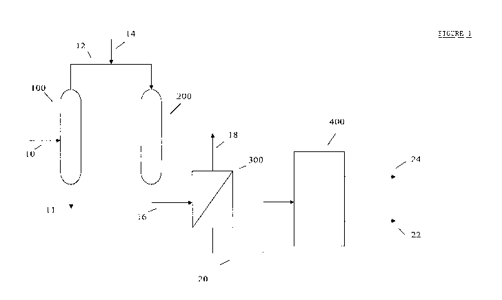
[0013] Figure 1 hereof is a simplified flow diagram of a
preferred embodiment of the present disclosure showing a solvent
extraction stage followed by a liquid-continuous hydrotreating
stage followed by a solvent dewaxing stage.
CA 02803378 2012-12-19
WO 2012/003272 PCT/US2011/042522
-5-
[0014] Figure 2 hereof is a simplified flow diagram of another
preferred embodiment of the present disclosure showing a solvent
extraction stage followed by a liquid-continuous hydrotreating
stage followed by a catalytic dewaxing stage followed by a
hydro finishing stage.
Detailed Description
[0015] All numerical values within the detailed description and
the claims herein are modified by "about" or "approximately" the
indicated value, and take into account experimental error and
variations that would be expected by a person having ordinary skill
in the art.
[0016] The present disclosure is directed to the preparation of
Group IT and Group III lube base oils. API Publication 1509:
Engine Oil Licensing and Certification System, "Appendix E-API
Base Oil Interchangeability Guidelines for Passenger Car Motor
Oil and Diesel Engine Oils" describes base oil categories. A Group
II base oil will contain greater than or equal to 90 wt.% saturates
and less than or equal to 0.03 wt.% sulfur and will have a viscosity
index greater than or equal to 80 and less than 120. A Group III
base oil will contain greater than or equal to 90 wt.% saturates and
less than or equal to 0.03 wt.% sulfur and will have a viscosity
index greater than or equal to 120. The term "viscosity index" (VI)
refers to the measurement defined by ASTM D2270.
[0017] Feedstocks suitable for use herein are preferably one or
a combination of refinery streams having a normal boiling point of
at least 600 F (316 C), although hydrocarbon refinery streams
having initial boiling points as low as 435 F (224 C) can also be
CA 02803378 2012-12-19
WO 2012/003272 PCT/US2011/042522
-6-
used. By having a normal boiling point of at least 600 F (316 C)
is meant that 85% by volume of the feedstock has a boiling point at
atmospheric pressure of at least 600 F (316 Q. While higher
boiling lube oil feedstocks can be processed in accordance with the
present disclosure, the preferred feedstock will have a boiling range
such that at least 85% by volume of the feedstock has a normal
boiling point of at most 1250 F (677 C), and more preferably at
most 1100 F (593 C). Such feedstocks, particularly vacuum gas
oils, will contain from 35 wt.% to 70 wt.% aromatics, at least 40%
of them being 2-ring and higher aromatics. Representative
feedstocks that can be treated in accordance with the present
disclosure include gas oils and vacuum gas oils (VGO),
hydrocracked gas oils and hydrocracked vacuum gas oils,
deasphalted oils, reduced crude, vacuum tower bottoms,
deasphalted vacuum resids. The nitrogen, sulfur and saturate
contents of these feeds will vary depending on a number of factors.
The preferred feedstocks for the present disclosure will have an
entrained oil viscosity of greater than 40. In a more preferred
embodiment, the entrained oil in the feedstock will have a viscosity
index in the range of 50 to 110.
[00181 Lube refineries are continually challenged to increase
throughput and to process more refractory feedstocks. Limitations
with respect to conventional solvent-based lube plants to
accomplish these objectives are the need for cost-effective
debottlenecking to handle increased rate, and the poor yields
associated with the extraction of very refractory feeds.
Additionally, conventional solvent-based lube refining are typically
unable, without high-pressure hydrotreating capacity, to meet the
Group II aromatics specification (10 wt.% max).
CA 02803378 2012-12-19
WO 2012/003272 PCT/US2011/042522
-7-
[0019] The process of the present disclosure represents a
cost-effective means for incorporating hydrotreating into a
conventional solvent-based lube refinery. This disclosure is better
understood with reference to the Figures hereof that illustrate the
primary pieces of equipment for practicing a preferred embodiment
of the present disclosure. Ancillary equipment, such as valves,
pumps, compressors, heat exchanger, heaters and the like are not
shown for simplicity reasons. Such ancillary equipment are well
known to those having ordinary skill in the art. A lube oil
feedstock is conducted via line 10 to solvent extraction stage 100.
[0020] Solvent extraction is a physical separation process that
uses a solvent to preferentially dissolve and remove aromatic and
other polar compounds from the lube oil feedstock that cause large
changes of viscosity with temperature. Solvent extraction removes
a portion of these components and improves viscosity index (VI),
oxidation stability, color, and oxidation inhibitor response. The VI
of an oil is an arbitrary relative measure of its change in viscosity
with temperature. The smaller the change in viscosity of an oil
with a given change in temperature the higher the VI value of the
oil. A high VI is desirable in high quality motor oils. The amount
of material extracted depends on the increase in VI required.
Extraction also reduces the Conradson carbon and sulfur content.
Low aromatic and sulfur contents are conducive to good oxidation
stability and color of the resulting base oils.
[0021] Solvent extraction is suitably carried out with solvents
such as N-Methyl-2-pyrrolidone, phenol, or furfural. The solvents
are chosen for their relative solubilization of aromatic-type
petroleum molecules, and for their relatively low boiling point,
CA 02803378 2012-12-19
WO 2012/003272 PCT/US2011/042522
-8-
which permits ease of separation of the solvent from the extract.
The extraction takes place in a solvent extractor. Any suitable
solvent extractor can be used in the practice of the present
disclosure. Non-limiting examples of solvent extractors that can be
used in the practice of the present disclosure include rotating disc
contactors, packed towers, baffle trayed towers, and centrifugal
contactors. If an asphalt-containing feedstock is used in the
practice of the present disclosure it is preferably deasphalted prior
to solvent extraction. Preferred solvents for deasphalting include
lower-boiling paraffinic hydrocarbons such as ethane, propane,
butane, pentane, or mixtures thereof. Propane is a preferred
deasphalting solvent and pentane is a most suitable solvent if high
yields of deasphalted oil are desired. These lower-boiling paraffinic
solvents can also be used as mixtures with alcohols, such as
methanol and isopropanol. Solvent extraction severity is typically
maintained at sufficient conditions to produce an extracted oil
product when dewaxed having a viscosity index of at least 80,
preferably at least 95.
[00221 The solvent extraction process for the preparation of a
lube oil feedstock useful in the present disclosure can be run at
lower severity than is commonly employed in the preparation of
high quality lubricating oil base stocks. Reduced solvent extraction
severity is seen in reduced solvent usage and/or in reduced solvent
extraction temperatures and can allow for increased throughput
through the extraction device. Decreasing the severity of the
solvent extraction step also results in higher yield, but it reduces
the VI of the entrained oil in the resulting raffinate. The "under-
extracted" raffinate has a higher concentration of aromatics and
heteroatoms, hence resulting in the need for an additional step to
CA 02803378 2012-12-19
WO 2012/003272 PCT/US2011/042522
-9-
increase VI to acceptable levels. Hydrotreating raffinates offers the
potential benefits of increasing the VI at low yield penalty while
reducing base oil aromatics to Group II levels. Very severe
hydrotreating operation can result in a VI increase large enough to
produce a Group III base oil.
[0023] Solvent extraction conditions can be maintained to
produce an oil product having a viscosity index which is at least 5
less, and preferably in the range of 5 to 20 less than the desired
viscosity index of the lubricating base oil prepared by the present
process. If the desired viscosity index of the Group II lubricating
base oil is 80, the solvent extraction pre-treatment step of the
present process is maintained to produce a lubricating oil feedstock
having a viscosity index of less than 75, preferably in the range
from 60 to 75. Likewise, if the desired viscosity index of the
Group II lubricating base oil is 95, solvent extraction is maintained
to produce a lubricating oil feedstock having a viscosity index of
less than 90, preferably in the range from 75 to 90.
[0024] Returning now to Figure 1 hereof, the extract from
solvent extraction 100 is sent, via line 11, for solvent recovery (not
shown). Solvent recovery technology is well known in the art and
a detailed discussion of it is not warranted in this application.
Solvent is typically recovered by conducting the extract to
equipment such as flash columns or steam strippers (not shown).
Multiple flash columns can improve overall heat utilization as
solvent recovered in higher pressure flash columns can be used
effectively to transfer heat content to hydrocarbon streams.
Process variables that affect solvent recovery include such things
as reflux ratios, pressure, temperature, and stripping steam within
CA 02803378 2012-12-19
WO 2012/003272 PCT/US2011/042522
- 10-
the constraints of solvent content of the raffinate and extract
streams.
[0025] The raffinate stream from solvent extraction 100 is sent
via line 12 to liquid-continuous hydrotreating stage 200 that will
primarily be a suitable reactor. Make-up hydrogen, as needed, can
be introduced via line 14. It will be understood that makeup
hydrogen can be added at any suitable point along the feed line or
even directly into reactor 200. It is also within the scope of this
disclosure that the gas-liquid flow to liquid-continuous
hydrotreating reactor 200 be blended under static mixing
conditions. By static mixing conditions we mean one or more,
preferably more, of geometric mixing elements fixed within a pipe
that use the energy of the moving stream to create mixing between
two or more fluids. Thus, the static mixers themselves have no
moving parts. The advantage of the static mixers of the present
disclosure over dynamic mixers, other than the fact that static
mixers have no moving parts, is that static mixers split the stream
hundreds, or even thousands of times, thus resulting in a
continuous phase containing very fine droplets of discontinuous
phase. This results in a much larger surface area when compared
with dynamic mixers. The gas-liquid mixture can also be flashed
in a suitable vessel before entering reactor 200 to remove at least a
portion of any excess gas. Alternatively, excess gas can be vented
(not shown) directly from reactor 200.
[0026] It may be necessary to recycle liquid product from the
liquid-continuous hydrotreating reactor to ensure that sufficient
hydrogen is present in the liquid phase for the reaction. The
recycled liquid serves as a carrier for additional solubulized
CA 02803378 2012-12-19
WO 2012/003272 PCT/US2011/042522
- 11 -
hydrogen. Alternatively, or in combination with this liquid recycle,
hydrogen may also be added to the reactor by withdrawing liquid at
one or more points, preferably at one or more axial points, along
the reactor, resaturating the liquid with hydrogen, then reinjecting
it back into the reactor. This approach can be used to reduce the
amount of required liquid recycle.
[00271 Because the liquid effluent from 200 will contain only
dissolved gas, it is not necessary to have a high-pressure separation
step downstream of the reactor. Only a low-pressure flash step is
needed to vent dissolved and excess gas before product
fractionation. Elimination of high-pressure product recovery
equipment significantly reduces the cost, particularly if this
disclosure is used for debottlenecking in an existing lubes plant.
[0028] As previously mentioned, reactor 200 used in this
disclosure is operated such that the liquid phase represents the
continuous phase in the reactor. Traditionally, hydroprocessing,
including hydrotreating, is conducted in trickle-bed reactors where
an excess of gas results in a continuous gas phase in the reactor. In
a liquid-continuous reactor, the feedstock is exposed to one or
more beds of catalyst. The liquid raffinate preferably enters from
the top or upper portions of the reactor and flows downward
through the catalyst beds of the reactor. This downward liquid
flow can assist in allowing the catalyst to remain in place in the
catalyst bed. An advantage of liquid-continuous reactors is that
they operate near isothermally. Because there are substantially no
hot spots within the reactor, this allows one to tune the operation of
the reactor to more precisely meet product quality needs.
CA 02803378 2012-12-19
WO 2012/003272 PCT/US2011/042522
-12-
[00291 A hydroprocessing process typically involves exposing
a feed to a suitable catalyst in the presence of hydrogen at effective
hydroprocessing conditions. Without being bound by any
particular theory, in a conventional trickle-bed reactor, the reactor
is typically operated so that three "phases" are present in the
reactor. The hydroprocessing catalyst corresponds to the solid
phase. Another substantial portion of the reactor volume is
occupied by a gas phase. This gas phase (second-phase) includes
the hydrogen for hydroprocessing, optionally some diluent gases,
and other gases such as contaminant gases that form during
hydroprocessing. The amount of hydrogen gas in the gas phase is
typically present in substantial excess relative to the amount
required for the hydroprocessing reaction. In a conventional
trickle-bed reactor, the solid hydroprocessing catalyst and the gas
phase can occupy at least 80% of the reactor volume, or at least
85%, or even at least 90%. The third "phase" corresponds to the
liquid feedstock. In a conventional trickle-bed reactor, the
feedstock will typically only occupy a small portion of the volume,
such as less than 20%, or less than 10%, or less than 5%. As a
result, the liquid feedstock will not form a continuous phase.
Instead, the liquid "phase" will include, for example, thin films of
feedstock that coat the hydroprocessing catalyst particles.
[00301 Without being bound by any particular theory, a liquid-
continuous reactor provides a different type of processing
environment as compared to a trickle-bed reactor. In a liquid-
continuous reactor, the reaction zone is primarily composed of only
two phases. One phase is a solid phase corresponding to the
hydroprocessing catalyst, in this case a hydrotreating catalyst. The
second phase is a liquid phase corresponding to the raffinate
CA 02803378 2012-12-19
WO 2012/003272 PCT/US2011/042522
- 13 -
feedstock. The liquid feedstock phase will be present as a
continuous phase in the liquid-continuous reactor of the present
disclosure. In an embodiment, the hydrogen that will be consumed
during the hydrotreating reaction is dissolved in the liquid phase.
Depending on the quantity of hydrogen used, a portion of the
hydrogen can also be in the form of bubbles of hydrogen in the
liquid phase. This hydrogen corresponds to hydrogen that is in
addition to the hydrogen dissolved in the liquid phase. In another
embodiment, hydrogen dissolved in the liquid phase can be
depleted as the reactions progress in the liquid-continuous reactor.
In such an embodiment, hydrogen initially present in the form of
gaseous bubbles can dissolve into the liquid phase to resaturate the
liquid phase and provide additional hydrogen for the reactions
taking place in the reactor. In various embodiments, the volume
occupied by a gas phase in the liquid-continuous reactor can be less
than 10% of the reactor volume, or even less than 5%.
[0031] The liquid feed to the reactor 200 is preferably mixed
with a hydrogen-containing treat gas. The hydrogen-containing
treat gas will preferably contain at least 50 vol% of hydrogen, more
preferably at least 80 vol%, even more preferably at least 90 vol%,
and most preferably at least 95 vol%. Excess gas can be vented
from the mixture before it enters the reactor, or excess gas can be
vented directly from the reactor. The liquid level in the reactor is
preferably controlled so that the catalyst in the reactor is
completely wetted.
[0032] In some embodiments, the hydrotreating reactions in a
bed, stage, and/or reactor can require more hydrogen than can be
dissolved in the fresh liquid feed. In such embodiments, one or
CA 02803378 2012-12-19
WO 2012/003272 PCT/US2011/042522
-14-
more techniques can be used to provide additional hydrogen for the
hydrotreating reaction. One option is to recycle a portion of the
product from the reactor. A recycled portion of product that has
already passed through a hydrotreating stage will likely have a
reduced hydrogen consumption as it passes again through the
hydrotreating stage. Additionally, the solubility of the recycled
feed can be higher than a comparable unprocessed feed. As a
result, including a portion of recycled product with fresh feed can
increase the amount of hydrogen available for reaction with the
fresh feed.
[00331 Another option is to introduce additional streams of
hydrogen into the hydrotreating reactor directly. One or more
additional hydrogen streams can be introduced at any convenient
location in the reactor. The additional hydrogen streams can
include a stream of make-up hydrogen, a stream of recycled
hydrogen, or any other convenient hydrogen-containing stream. In
some embodiments, both product recycle and injection of
additional hydrogen streams along the axial dimension of the
reactor can be used to provide sufficient hydrogen for a reaction.
[00341 In embodiments involving recycle of the liquid-
continuous hydrotreated product for use as part of the input to
reactor 200, the ratio of the amount by volume of product recycle
to the amount of fresh feed into reactor 200 will be at least 0.5 to 1,
or at least 1 to 1, or at least 1.5 to 1. The ratio of the amount by
volume of product recycle to the amount of fresh feed can be 5 to 1
or less, or 3 to 1 or less, or 2 to 1 or less.
[00351 The hydrotreating catalyst of the present disclosure will
contain at least one of Group VIB and/or Group VIII metals
CA 02803378 2012-12-19
WO 2012/003272 PCT/US2011/042522
- 15 -
optionally on a support. Any suitable refractory support material
can be used in the practice of this disclosure. Non-limiting
examples of such suitable support materials include alumina, silica,
silica alumina, titania, zirconia, silica-alumina, combinations of the
above. Examples of Group VIB metals that can be used herein
include molybdenum, tungsten, or a combination thereof.
Examples of Group VIII metals that can be used herein include
nickel, cobalt, iron, or combinations thereof. All Groups referred
to herein are as found in the Sargent-Welch Periodic Table of the
Elements copyrighted in 1968 by the Sargent-Welch Scientific
Company. Preferred catalyst compositions contain in excess of 5
wt.% Group VIB metals, preferably 5 to 40 wt.% molybdenum
and/or tungsten, and at least 0.5 wt.%, and generally 1 to 15 wt.%
of nickel and/or cobalt determined as the corresponding oxides.
Hydrotreating catalysts of this type are readily available from
catalyst suppliers. These catalysts are generally presulfided using
H2S or other suitable sulfur containing compounds.
[00361 Bulk multimetallic catalysts can also be used for
aromatics saturation in the practice of the present disclosure. Such
catalysts are described in U.S. Patent Nos. 6,156,695; 6,162,350;
and 6,299,760, all of which are incorporated herein by reference.
The catalysts described in these patents are bulk multimetallic
catalysts comprised of at least one Group VIII non-noble metal and
at least two Group VIB metals, wherein the ratio of Group VIB
metal to Group VIII non-noble metal is from 10:1 to 1:10. These
catalysts are prepared from a precursor having the formula:
(X)a (MO)b (W)d Oz
CA 02803378 2012-12-19
WO 2012/003272 PCT/US2011/042522
- 16-
where X is a Group VIII non noble metal, wherein the molar ratio
of and a, b, and c, are such that 0.1 <(b+c)/b<10, and z = [2a + 6
(b+c)]/2. The precursor has x-ray diffraction peaks at d = 2.53 and
1.70 Angstroms. The precursor is sulfided to produce the
corresponding activated catalyst.
10037] The degree of aromatics saturation and desulfurization
activity of the catalyst may be found by experimental means, using
a feed of known composition under fixed hydrotreating conditions.
[00381 Control of the reaction parameters of the hydrotreating
step also offers a useful way of varying product properties. As
hydrotreating temperature increases the degree of desulfurization
increases; although hydrogenation is an exothermic reaction
favored by lower temperatures, desulfurization usually requires
some ring-opening of heterocyclic compounds to occur and these
reactions being endothermic, are favored by higher temperatures. If
the temperature during the hydrotreating step can be maintained at
a value below the threshold at which excessive desulfurization
takes place, products of improved oxidation stability are obtained.
When a bimetallic such as nickel-molybdenum for the
hydrotreating catalyst is used, temperatures of 400 F to 800 F
(205 C to 427 C), preferably 600 F to 750 F (316 C to 399 C) are
recommended for good oxidative stability. Space velocity in the
hydrotreater also offers a potential for desulfurization control with
the higher velocities corresponding to lower severities resulting in
a reduction in the degree of desulfurization. The hydrotreated
product preferably has an organic sulfur content of less than 300
wppm, preferably less than 200 wppm.
CA 02803378 2012-12-19
WO 2012/003272 PCT/US2011/042522
-17-
[0039] Variation of hydrogen pressure during the hydrotreating
step also enables the desulfurization to be controlled with lower
pressures generally leading to less desulfurization as well as a
lower tendency to saturate aromatics, and eliminate peroxide
compounds and nitrogen, all of which are desirable. A balance may
therefore need to be achieved between a reduced degree of
desulfurization and a loss in the other desirable effects of the
hydrotreating. Generally, pressures of 200 to 2200 psig (1480 to
15300 kPa abs) are satisfactory with pressures of 1000 to 1500 psig
(7000 to 10450 kPa abs) giving good results with appropriate
selection of metal function and other reaction conditions made
empirically by determination of the desulfurization taking place
with a given feed.
[0040] Hydrotreating is performed by exposing a feedstock to a
hydrotreating catalyst under effective hydrotreating conditions.
Effective hydrotreating conditions include temperatures of at least
600 F to 750 F, pressures from 200 to 2200 psi, a liquid hourly
space velocity (LHSV) over the hydrotreating catalyst of 0.2 to 5,
and a treat gas rate of 500 to 10,000 standard cubic feet per barrel
(scf/bbl). In still another embodiment, the temperature, pressure,
and LHSV for a liquid-continuous reactor can be conditions
suitable for use in a trickle-bed reactor.
[0041] In embodiments where excess gas is vented from the
liquid, the available hydrogen in the reactor corresponds to the
amount of hydrogen dissolved in the liquid. Thus, a higher treat
gas rate may not lead to an increase in the amount of available
hydrogen. In such a situation, the effective treat gas rate within a
reactor may be dependent on the solubility limit of the feedstock.
CA 02803378 2012-12-19
WO 2012/003272 PCT/US2011/042522
-18-
The hydrogen solubility limit for a typical hydrocarbon feedstock
is 30 scf/bbl to 200 scf/bbl.
[0042] One advantage of a liquid-continuous reactor is that a
large excess of hydrogen does not have to be fed to the reactor.
The use of a large excess of hydrogen typically requires complex
and expensive separation equipment to allow for recovery, and
often recycling, of the excess hydrogen. Typically the recycle
compressor used for hydrogen recycle in a trickle-bed reactor
corresponds to 10 to 15% of the total cost of the erected processing
unit. Instead, it is desirable for a liquid-continuous reactor will
desirably supply only an amount of hydrogen comparable to the
amount needed for a hydroprocessing reaction and to mitigate
catalyst coking. For example, a hydrotreating process can consume
from 150 scf/bbl (27 sm3/m3) of hydrogen to 1000 scf/bbl (180
sm3/m3).
[0043] Returning now to Figure 1 hereof, the effluent stream
from 200 is conducted via line 16 to separation zone 300 wherein a
gaseous phase, which is primarily comprised of excess hydrogen
and contaminant gases such as ammonia and H2S, is separated
from the hydrotreated liquid raffinate phase. The gaseous phase
can be vented or sent via line 1S for further processing or recycle.
The hydrotreated liquid raffinate phase is conducted via line 20 to
dewaxing stage 400. Although dewaxing stage 400 can be either a
solvent dewaxing or catalytic dewaxing process, for purposes of
this Figure 1, the dewaxing stage is solvent dewaxing.
[0044] Solvent dewaxing typically involves mixing a raffinate
feed from the solvent extraction unit with chilled dewaxing solvent
to form an oil-solvent solution and precipitated wax is thereafter
CA 02803378 2012-12-19
WO 2012/003272 PCT/US2011/042522
- 19-
separated by, for example filtration. The temperature and solvent
are selected so that the oil is dissolved by the chilled solvent while
the wax is precipitated. In this case, the raffinate feed is
hydrotreated before being sent to dewaxing.
[0045] A preferred solvent dewaxing process involves the use
of a cooling tower where solvent is prechilled and added
incrementally at several points along the height of the cooling
tower. The oil-solvent mixture is agitated during the chilling step
to permit substantially instantaneous mixing of the prechilled
solvent with the oil. The prechilled solvent is added incrementally
along the length of the cooling tower so as to maintain an average
chilling rate at or below 10 F per minute, usually between 1 to 5 F
per minute. The final temperature of the oil-solvent/precipitated
wax mixture in the cooling tower will usually be between 0 and
50 F (-17.8 to 10 C). The mixture may then be sent to a scraped
surface chiller to separate precipitated wax from the mixture.
[0046] In general, the amount of solvent added will be
sufficient to provide a liquid/solid weight ratio from 5 to 1 to 20 to
1 at the dewaxing temperature and at a solvent/oil volume ratio at
1.5 to 1 to 5 to 1. The solvent dewaxed oil is typically dewaxed to
an intermediate pour point, preferably less than +10 C.
[0047] Non-limiting examples of dewaxing solvents that can
be used in the practiced of the present disclosure include aliphatic
ketones having 3-6 carbon atoms such as methyl ethyl ketone and
methyl isobutyl ketone, low molecular weight hydrocarbons such
as propane and butane, and mixtures thereof. These solvents can
be mixed with one or more other solvents such as benzene, toluene
or xylene. Further descriptions of solvent dewaxing processes
CA 02803378 2012-12-19
WO 2012/003272 PCT/US2011/042522
-20-
useful herein are disclosed in U.S. Pat. Nos. 3,773,650 and
3,775,288 both of which are incorporated herein in their entirety by
reference.
[00481 Returning again to Figure 1 hereof two streams are
collected from solvent dewaxing stage 400. A precipitated wax via
line 22 and a Group II or Group III base oil via line 24.
[00491 Figure 2 hereof is a schematic flow diagram of another
embodiment of the present disclosure wherein catalytic dewaxing
is used instead of solvent dewaxing. All components and numbers
of this Figure 2 are identical to that of Figure 1 hereof up to and
including hydrotreating zone 200. The hydrotreated raffinate
stream from separation zone 300 is passed via line 20 to catalytic
dewaxing stage 400. The dewaxed stream is passed via line 30 to
second separation zone 600 where a gaseous effluent stream is
removed as an off-gas via line 32 and the dewaxed liquid effluent
stream is passed via line 34 to stripper 700 to remove any
remaining gaseous moieties. The resulting Group II or Group III
base oil is collected via line 36, which base oil will at least meet
the API Group II base oil requirements as previously discussed.
[00501 Instead of conducting the effluent stream from
hydrotreating stage 200 to separation zone 300 it can alternatively
be conducted, via lines 17 and 20 directly to dewaxing stage 500.
Because contaminant gases are not removed with this alternative,
the dewaxing catalyst would operate in a sour environment, thus
hydrogen consumption would be relatively low, potentially
obviating the need for liquid recycle to the dewaxing reactor if it
were a liquid-continuous reactor. It is preferred that the effluent
CA 02803378 2012-12-19
WO 2012/003272 PCT/US2011/042522
-21 -
stream from hydrotreating stage 200 be first passed to separation
zone 300 instead of being directly passed to dewaxing stage 500.
[00511 Catalytic dewaxing is performed by exposing the
hydrotreated raffinate to a dewaxing catalyst under effective
(catalytic) dewaxing conditions. Effective dewaxing conditions
can include a temperature of at least 500 F (260 C), or at least
550 F (288 C), or at least 600 F (316 C), or at least 650 F
(343 C). Alternatively, the temperature can be 750 F (399 C) or
less, or 700 F (371 C) or less, or 650 F (343 C) or less. The
pressure can be at least 200 psig (1.4 MPa), or at least 400 psig (2.8
MPa), or at least 750 psig (5.2 MPa), or at least 1000 psig (6.9
MPa). Alternatively, the pressure can be 2200 psig (15.3 MPa) or
less, or 1500 prig (10.4 MPa) or less, or 1000 psig (6.9 MPa) or
less, or 800 psig (5.5 MPa) or less. The liquid hourly space
velocity (LHSV) over the dewaxing catalyst can be at least 0.1 hr 1,
or at least 0.2 hr 1, or at least 0.5 hr-1, or at least 1.0 hr 1, or at least
1.5 hr 1. Alternatively, the LHSV can be 10.0 hr -1 or less, or 5.0
hr-1 or less, or 3.0 hr -1 or less, or 2.0 hrI or less. In still another
embodiment, the temperature, pressure, and LHSV for a liquid-
continuous reactor can be the same conditions typically used for a
trickle-bed reactor.
[00521 Catalytic dewaxing involves the removal and/or
isomerization of long chain, paraffinic molecules from feeds.
Catalytic dewaxing can be accomplished by selective cracking or
by hydroisomerizing these linear molecules. Hydrodewaxing
catalysts can be selected from molecular sieves such as crystalline
aluminosilicates (zeolites) or silico-aluminophosphates (SAPOs).
In an embodiment, the molecular sieve can be a 1-D or 3-D
CA 02803378 2012-12-19
WO 2012/003272 PCT/US2011/042522
-22-
molecular sieve. In another embodiment, the molecular sieve can
be a 10-member ring 1-D molecular sieve. Examples of molecular
sieves which have shown dewaxing activity in the literature can
include ZSM-48, ZSM-22, ZSM-23, ZSM-35, Beta, USY, ZSM-5,
and combinations thereof. In an embodiment, the molecular sieve
can be ZSM-22, ZSM-23, ZSM-35, ZSM-48, or a combination
thereof. In still another embodiment, the molecular sieve can be
ZSM-48, ZSM-23, ZSM-5, or a combination thereof. In yet
another embodiment, the molecular sieve can be ZSM-48,
ZSM-23, or a combination thereof. Optionally, the dewaxing
catalyst can include a binder for the molecular sieve, such as
alumina, titania, silica, silica-alumina, zirconia, or a combination
thereof.
[0053] The dewaxing catalyst can also include a metal
hydrogenation component, such as a Group VIII metal. Suitable
Group VIII metals can include Pt, Pd, Ni, or a combination thereof.
The dewaxing catalyst can include at least 0.1 wt% of a Group VIII
metal, or at least 0.3 wt%, or at least 0.5 wt%, or at least 1.0 wt%,
or at least 2.5 wt%, or at least 5.0 wt%. Alternatively, the
dewaxing catalyst can include 10.0 wt% or less of a Group VIII
metal, or 5.0 wt% or less, or 2.5 wt% or less, or 1.5 wt% or less, or
1.0 wt% or less.
[0054] In some embodiments, the dewaxing catalyst can also
include at least one Group VIB metal, such as W or Mo. Such
Group VIB metals are typically used in conjunction with at least
one Group VIII metal, such as Ni or Co. An example of such an
embodiment is a dewaxing catalyst that includes Ni and W, Mo, or
a combination of W and Mo. In such an embodiment, the
CA 02803378 2012-12-19
WO 2012/003272 PCT/US2011/042522
- 23 -
dewaxing catalyst can include at least 0.5 wt% of a Group VIB
metal, or at least 1.0 wt%, or at least 2.5 wt%, or at least 5.0 wt%.
Alternatively, the dewaxing catalyst can include 20.0 wt% or less
of a Group VIB metal, or 15.0 wt% or less, or 10.0 wt% or less, or
5.0 wt% or less, or 1.0 wt% or less. In an embodiment, the
dewaxing catalyst can include Pt, Pd, or a combination thereof. In
another embodiment, the dewaxing catalyst can include Co and
Mo, Ni and W, Ni and Mo, or Ni, W, and Mo.
[00551 In the case where catalytic dewaxing is used, makeup
hydrogen-containing treat gas can be added as needed upstream of
the catalytic dewaxing reactor. The effluent from the catalytic
dewaxing zone can then be sent to a liquid/gas separator wherein
the gaseous effluent is separated from the liquid effluent. The
gaseous effluent, can be vented or sent to further processing and
the liquid effluent can be sent to a stripper to remove light
byproducts.
[00561 It is within the scope of this disclosure that there be two
dewaxing steps run in parallel. One dewaxing step would be
solvent dewaxing and the other catalytic dewaxing. One type of
base oil can be solvent dewaxed while another is catalytically
dewaxed. If it is desired to produce Group II base oils in a
conventional lube plant and to increase base oil product, the
addition of both a hydrotreating process unit and a dewaxing unit
would be required. In such a case catalytic dewaxing would be
preferred because it would be the least costly option and would be
well integrated with the hydrotreater.
[00571 It will be understood that a hydrofinishing step can
follow either solvent dewaxing or catalytic dewaxing. If catalytic
CA 02803378 2012-12-19
WO 2012/003272 PCT/US2011/042522
-24-
dewaxing is used, it is preferred that a hydrofinishing step follow
dewaxing. Hydrofinishing is a mild, relatively cold hydrotreating
process, that employs a catalyst, hydrogen and mild reaction
conditions to remove trace amounts of heteroatom compounds,
aromatics and olefins, to improve primarily oxidation stability and
color. Hydrofinishing reaction conditions include temperatures
from 300 F to 675 F. (149 C to 357 C_), preferably from 400 F to
600 F. (204 C to 316 C.), a total pressure of from 400 to 2200 psig
(2860 to 15270 kPa abs), a liquid hourly space velocity ranging
from 0.1 to 5 LH S V (hr" 1), preferably 0.5 to 3 hr -1. The hydrogen
treat gas rate will range from 500 to 5000 scf/bbl (89 to 890
m3/m3). Hydrofinishing following solvent dewaxing will normally
be conducted at pressures between 200 and 1000 psig while
hydrofinishing following catalytic dewaxing will normally be
conducted at a pressure similar to that of the dewaxing step. The
hydrofinishing catalyst can comprise a support component and one
or more catalytic metal components. The one or more metals are
selected from Group VIB (Mo, W, Cr) and Group VIII (Ni, Co and
the noble metals Pt and Pd) which Groups are found in the Sargent-
Welch Periodic Table of the Elements copyrighted in 1968 by the
Sargent-Welch Scientific Company. The metal or metals may be
present from as little as 0.1 wt% for noble metals, to as high as 30
wt% of the catalyst composition for non-noble metals. Preferred
support materials are low in acid and include, for example,
amorphous or crystalline metal oxides such as alumina, silica,
silica alumina and ultra large pore crystalline materials known as
mesoporous crystalline materials, of which MCM-41 is a preferred
support component. Un-supported base metal (non-noble metal)
catalysts are also applicable as hydrofinishing catalysts.
CA 02803378 2012-12-19
WO 2012/003272 PCT/US2011/042522
-25-
[0058] The effluent stream from hydrofinishing can be passed
to a separation zone wherein a gaseous effluent stream is separated
from the resulting liquid phase lube oil base stock. The gaseous
effluent stream, a portion of which will be unreacted hydrogen-
containing treat gas can be recycled to hydrotreating stage 200.
The resulting lube oil base stock, will meet Group II or Group III
base oil requirements.
[0059] All patents and patent applications, test procedures
(such as ASTM methods, UL methods, and the like), and other
documents cited herein are fully incorporated by reference to the
extent such disclosure is not inconsistent with this disclosure and
for all jurisdictions in which such incorporation is permitted.
[0060] When numerical lower limits and numerical upper
limits are listed herein, ranges from any lower limit to any upper
limit are contemplated. While the illustrative embodiments of the
disclosure have been described with particularity, it will be
understood that various other modifications will be apparent to and
can be readily made by those skilled in the art without departing
from the spirit and scope of the disclosure. Accordingly, it is not
intended that the scope of the claims appended hereto be limited to
the examples and descriptions set forth herein but rather that the
claims be construed as encompassing all the features of patentable
novelty which reside in the present disclosure, including all
features which would be treated as equivalents thereof by those
skilled in the art to which the disclosure pertains.
[0061] The present disclosure has been described above with
reference to numerous embodiments and specific examples. Many
variations will suggest themselves to those skilled in this art in
CA 02803378 2012-12-19
WO 2012/003272 PCT/US2011/042522
-26-
light of the above detailed description. All such obvious variations
are within the full intended scope of the appended claims.