Note: Descriptions are shown in the official language in which they were submitted.
CA 02803483 2012-12-20
WO 2011/162615 PCT/N02011/000175
OCEAN WAVE ENERGY SYSTEM
Field of the invention
The present invention relates to ocean wave energy systems for generating
energy from
ocean wave motion, wherein the systems include one or more hollow tubes
disposed at one
or more non-vertical angles for receiving ocean waves at their one or more
lower open ends,
wherein the ocean waves are operable to compress in a cyclical manner fluid
within the one
or more hollow tubes for power generation purposes, and wherein the one or
more hollow
tubes are optionally adapted so that their natural resonant frequency of wave
motion therein
is substantially equal in operation to a frequency of ocean waves received at
the lower ends
of=the one or more hollow tubes for achieving enhanced energy conversion
efficiency, for
example by inclining and thereby changing hydrodynamic mass and stiffness of
the one or
more hollow tubes for modifying their natural resonant frequencies. Moreover,
the present
invention also relates to ocean wave energy systems for generating energy from
ocean wave
motion, wherein the systems include submerged structures, for example planar
elements, for
providing improved matching of received ocean waves to one or more hollow
tubes of the
systems disposed at one or more non-vertical angles for receiving ocean waves
at their
lower open ends, wherein the ocean waves are operable to compress fluid in a
cyclical
manner within the one or more hollow tubes for power generation purposes.
Moreover, the
present invention also concerns methods of using such systems for generating
energy from
ocean wave motion, wherein the methods optionally concern substantially
matching in
operation natural resonant frequencies of wave motion within one or more
hollow tubes of
the systems to one or more frequencies of ocean waves received at one or more
lower ends
of the one or more hollow tubes. Moreover, the present invention also concerns
methods of
using such systems for generating energy from ocean wave motion, wherein the
method
concerns adjusting the submerged structures for providing an enhanced matching
between
received ocean waves and energy collection arrangements included within the
systems.
Furthermore, the present invention also relates to structures including, for
example, one or
more planar elements which are submerged in operation and which provide an
enhanced
matching between received ocean waves and energy collection devices.
Additionally, the
present invention is also concerned with fluid valves for use in aforesaid
ocean wave energy
systems for controlling fluid flow to and/or from the one or more hollow tubes
during power
generation. Yet additionally, the present invention is concerned with turbine
arrangements
for use in systems pursuant to the present invention.
CA 02803483 2012-12-20
WO 2011/162615 PCT/N02011/000175
-2-
Background of the invention
Ocean waves are generated in an ocean region by wind acting upon an upper
surface of the
ocean region. Wind is itself caused by spatial differences in atmospheric
temperature as a
consequence of solar radiation being absorbed at the Earth. Ocean waves are
effectively
surface waves which are devoid of any general overall flow of ocean water, but
merely an
oscillatory motion of water about a mean position. Energy content of ocean
waves reduces
exponentially with depth from an upper ocean surface at a rate depending upon
ocean wave
wavelength. In a similar manner to other types of waves, for example
electromagnetic
waves, ocean waves can be reflected, diffracted, refracted and absorbed.
Renewable energy systems adapted for generating energy from ocean waves have
to
contend with numerous technical challenges. For example, ocean water is
corrosive.
Moreover, ocean waves vary greatly in amplitude, wavelength and complexity
with time.
Ocean wave energy can often be an order of magnitude greater under storm
conditions in
comparison to normal conditions. Moreover, situations can arise wherein ocean
wave
energy is negligible. Additionally, designers of ocean wave energy systems
have to consider
commercial viability of such systems in comparison to alternative systems such
as wind
turbine power generation systems, hydroelectric power systems, tidal power
generation
systems, fossil fuel burning power generation systems and nuclear power
systems; many
renewable energy systems suffer a problem of requiring costly robust
structures, for example
to withstand storm conditions, whilst generating relatively modest amounts of
power when in
operation in comparison to a corresponding size of a nuclear power station or
fossil fuel
power station. Thus, in order to improve commercial viability of ocean wave
energy systems,
it is highly desirable to ensure that such systems are designed and
implemented to exhibit an
enhanced operating efficiency for converting energy of ocean waves to
electrical energy or
similar alternative useful types of energy whilst simultaneously exhibiting
sufficient
robustness to survive storm conditions.
Many systems have been proposed for extracting useful energy from waves, for
example
using configurations of floats moving with ocean waves and coupled to pump
hydraulic fluids
to generate electrical power, ramps for receiving waves with upper overflow
ridges for the
waves to flow over to be collected to drive a turbine and vertical oscillating
columns wherein
ocean waves periodically compress air in the columns for actuating an air
turbine for
generating electricity. In a published Norwegian patent no. NO 327593
attributed to Geir
Arne Solheim, there is described an air column 10 disposed in operation at an
oblique angle
a relative to a general surface plane 20 of an ocean environment 30, as shown
in FIG. 1. A
first end of the column 10 is arranged to receive waves 40 in operation. A
second end of the
CA 02803483 2012-12-20
WO 2011/162615 PCT/N02011/000175
-3-
column 10 is coupled via air valves to an air turbine 50 for generating
electricity. The angle a
is beneficially in a range of 100 to 35 . Although the air column 10 disposed
at the oblique
angle a provides a considerable improvement in operating efficiency in
comparison to early
vertical oscillating air columns for generation of electrical power from ocean
waves, it is
desirable to improve further operating efficiency of an arrangement as
illustrated in FIG. 1 for
ensuring its commercial competitiveness against other sources of energy, for
example fossil
fuels and nuclear power systems.
Summary of the invention
The present invention seeks to improve further the efficiency of ocean wave
energy systems
utilizing oscillating air columns.
The present invention seeks to further improve the efficiency of ocean wave
energy systems
utilizing oscillating air columns tuned to a period of received ocean waves
thereat by using
an inclination angle of the oscillating air columns to adjust natural periods
in responses
provided by the columns when in operation.
According to a first aspect of the invention, there is provided an ocean wave
energy system
as claimed in appended claim 1: there is provided an ocean wave energy system
for
generating power from ocean waves, wherein the system includes a platform
supporting an
array of hollow columns whose respective lower ends are in fluidic
communication with
ocean waves and whose respective upper ends are in air communication with a
turbine
arrangement such that wave motion occurring at the lower ends is operable to
cause air
movement within the columns for propelling the turbine arrangement to generate
power
output, characterized in that the hollow columns are deployed in a non-
vertical orientation,
and at least a portion of the hollow columns are arranged in operation to
exhibit a natural
frequency of wave motion therein which is substantially matched to a frequency
of ocean
waves received at the portion of the hollow columns.
The invention is of advantage in that tuning of the system enables the system
to convert
ocean wave energy to useable energy in a more efficient manner.
Optionally, the ocean wave energy system is implemented so that the hollow
columns are
implemented so that their natural frequency of wave motion therein is actively
tuneable.
Optionally, the ocean wave energy system is implemented so that the array of
hollow
columns are disposed with their elongate axes at an oblique angle in a range
of 10 to 900,
CA 02803483 2012-12-20
WO 2011/162615 PCT/N02011/000175
-4-
and more preferable in a range of 25 to 750 relative to an average level of
an upper surface
of an ocean environment in which the system is located in operation.
Alternatively, the
ocean wave energy system is implemented so that the array of hollow columns
are disposed
with their elongate axes at an oblique angle in a range of 100 to 35 relative
to an average
level of an upper surface of an ocean environment in which the system is
located in
operation.
Optionally, the ocean wave energy system is implemented so that the array of
hollow
columns include hollow columns having mutually different natural resonant
frequencies in
respect of wave motion therein for selectively matching to different
frequencies of waves
received from an ocean environment.
Optionally, the ocean wave energy system is implemented so that the turbine
arrangement
includes at least one turbine operable to rotate about a substantially
vertical axis in operation
for gyroscopically stabilizing the platform when operating in an ocean
environment.
Optionally, the ocean wave energy system is implemented to include one or more
wind
turbines mounted upon the platform for generating power from wind received at
the system.
More optionally, the ocean wave energy system is implemented so that the one
or more wind
turbines are mounted at least at spatial extremes of the platform. More
optionally, the ocean
wave energy system is implemented so that the one or more wind turbines
include one or
more vertical-axis wind turbines, for example Darrieus-type vertical-axis wind
turbines. Such
Darrieus-type turbines are beneficial in that their rotation in operation is
susceptible to assist
to stabilize the platform by way of Coriolis forces.
Optionally, the ocean wave energy system is implemented to include one or more
aquaculture facilities. More optionally, the one or more aquaculture
facilities are adapted to
be submergible in an ocean environment in response to changes in weather
conditions
experienced by the system when in operation.
According to a second aspect of the present invention, there is provided an
ocean wave
energy system as defined in appended claim 12: there is provided an ocean wave
system for
generating power from ocean waves, wherein the system includes a platform
supporting an
array of hollow columns whose respective lower ends are in fluidic
communication with
ocean waves and whose respective upper ends are in air communication with a
turbine
arrangement such that wave motion occurring at the lower ends is operable to
cause air
movement within the columns for propelling the turbine arrangement to generate
power
CA 02803483 2012-12-20
WO 2011/162615 PCT/N02011/000175
-5-
output, characterized in that the system further includes one or more position-
adjustable
and/or angle-adjustable submerged structures near the lower ends of the
columns for
forming ocean waves propagating in operation towards the lower ends of the
columns to
couple the waves in a controllable manner into the hollow columns, and wherein
the
submerged structures are implemented as one or more planar structures provided
with an
actuator arrangement for displacing and/or tilting the one or more planar
structures relative to
the array of columns.
The invention is of advantage in that the one or more submerged structures are
capable of
improving ocean wave coupling to the array of columns, thereby enabling a
greater portion of
wave energy to be converted to output power from the system in operation.
In other words, the one or more submerged structures are operable to provide
dynamically-
adjustable wave impedance matching from an ocean environment to a local
environment
within the columns, namely for improving matching of ocean waves to the
columns under
dynamically varying wave conditions within the ocean environment..
Optionally, the ocean wave energy system is implemented so that the submerged
structures
are implemented as one or more planar structures provided with an actuator
arrangement for
displacing and/or tilting the one or more planar structures relative to the
array of columns.
Optionally, the ocean wave energy system is implemented to include a sensing
arrangement
for determining one or more characteristics of ocean waves propagating in
operation towards
the columns and their associated submerged structures, and a control
arrangement for
receiving wave-characteristic indicative signals from the sensing arrangement
and for
processing the signals for regulating positions and/or angles of the submerged
structures for
providing a dynamically responsive control of the submerged structures. More
optionally,
the ocean wave energy system is implemented so that the control arrangement is
implementing using computing hardware implementing at least one of:
(a) controlled adjustment of the submerged arrangement by way of employing a
numerical model representative of operating properties of the system; and
(b) use of a neural network whose neural weightings are adapted for
controlling operation
of the system in response to sensed wave conditions.
Optionally, the ocean wave energy system is implemented so that the array of
hollow
columns are disposed with their elongate axes at an oblique angle in a range
of 10 to 35
CA 02803483 2012-12-20
WO 2011/162615 PCT/N02011/000175
-6-
relative to an average level of an upper surface of an ocean environment in
which the system
is located in operation.
Optionally, the ocean wave energy system is implemented so that the turbine
arrangement
includes at least one turbine operable to rotate about a substantially
vertical axis in operation
for gyroscopically stabilizing the platform when operating in an ocean
environment. Such
gyroscopic stabilization utilizes Coriolis forces.
Optionally, the ocean wave energy system is implemented so that the platform
is adapted to
be rotatable in operation to enable the array of columns to be orientated in
respect of ocean
waves received at the system. More optionally, the system is implemented to
comprise a
sensor arrangement for sensing a prevailing propagation direction of the waves
to be
received at the array of columns, and an actuator arrangement for adjusting an
angular
orientation of the array of columns relative to the prevailing propagation
direction of the
waves.
Optionally, the ocean wave energy system is deployable:
(a) along a coast line;
(b) as one or more floating islands;
(c) as a floating peninsula or bow;
(d) as a floating bridge providing a transport route between land masses;
(e) mounted to foundations on an ocean floor, namely seabed.
Optionally, the ocean wave energy system is implemented to include aquaculture
facilities
adapted to be submerged for protection substantially beneath the system in
adverse weather
conditions which could damage the aquaculture facilities.
According to a third aspect of the present invention, there is provided a
method of operating
an ocean wave energy system pursuant to the first and/or second aspect of the
invention,
wherein the method includes:
(a) receiving one or more ocean waves in a vicinity of the one or more
submerged
structures for adjustably influencing an energy field of the one or more waves
to form
the one or more waves for being received at an array of air columns of the
system;
and
(b) receiving the one or more waves at the array of columns for periodically
compressing
and/or rarefying air in the one or more columns for driving a turbine
arrangement for
generating power,
CA 02803483 2012-12-20
WO 2011/162615 PCT/N02011/000175
-7-
wherein the submerged structures are implemented as one or more planar
structures
provided with an actuator arrangement for displacing and/or tilting the one or
more planar
structures relative to the array of columns.
According to a fourth aspect of the present invention, there is provided a
method of
controlling an ocean wave energy system pursuant to the first aspect of the
invention,
wherein the method includes:
(i) sensing one or more characteristics of ocean waves approaching the ocean
wave
energy system to generate corresponding sensor signals;
(ii) processing the sensor signals in a processing arrangement to generate
corresponding control signals; and
(iii) applying the signals to actuators coupled to one or more position-
adjustable and/or
angle-adjustable submerged structures near lower ends of columns of the system
for
forming the sensed ocean waves propagating in operation towards the lower ends
of
the columns to couple the waves in a controllable manner into the hollow
columns for
generating corresponding output power.
Optionally, the method is implemented so that the processing arrangement is
operable to
apply a numerical model and/or a neural network for generating the control
signals from the
sensor signals.
Optionally, the method includes:
(iv) sensing a propagating direction of ocean waves to be received at the
array of
columns; and
(v) rotatably orientating the array of columns relative to the propagating
direction of the
ocean waves.
According to a fifth aspect of the invention, there is provided a software
product recorded on
a machine-readable data carrier, wherein the software product is executable on
computing
hardware for implementing a method pursuant to the second and/or third aspect
of the
invention.
According to a sixth aspect of the invention, there is provided a fluid valve
for use with one or
more columns of an ocean wave energy system pursuant to the first aspect
and/or second
aspect of the present invention, characterized in that the fluid valve
includes a plurality of
mutually abutting components each including one or more apertures, wherein:
(i) the components are moveable between a first state (Ml) wherein the one or
more
apertures are mutually non-aligned for preventing fluid flow through the
valve, and a
CA 02803483 2012-12-20
WO 2011/162615 PCT/N02011/000175
-8-
second state (M2) wherein the one or more apertures are mutually aligned for
enabling fluid flow through the valve;
(ii) movement of the components is operable to provide the fluid valve with a
self-
cleaning function for preventing marine growth upon the components; and
(iii) interfacing surfaces between the components are arranged to be a water-
lubricated
electrostatic bearing by way of one of the interfacing surfaces being
hydrophobic in
nature abutting onto a corresponding interfacing surface being hydrophilic in
nature.
According to a seventh aspect of the invention, there is provided a turbine
arrangement for
use with an ocean wave energy system pursuant to the first and/or second
aspect of the
invention, wherein the turbine is operable to perform unidirectional rotation
in response to
bidirectional fluid flow therethrough, characterized in that the turbine
arrangement includes a
plurality of radial turbine components which are each provided with a
corresponding energy
pickoff arrangement, and a plurality of vane elements coupling between the
plurality of radial
turbine components and/or mounted upon an arrangement coupling between the
plurality of
radial turbine components, wherein a relative rotation angle between the
plurality of radial
turbine components is operable to control pitch angles of the plurality of
vane elements for
adapting the turbine arrangement to maintain a unidirectional rotation
direction in response to
bidirectional fluid flow therethrough.
Optionally, the turbine arrangement includes an electronic control arrangement
for selectively
applying drag or torque to the plurality of radial turbine components for
adjusting the pitch
angles of the plurality of vane elements.
Optionally, the turbine arrangement further includes a locking arrangement for
angularly
locking the plurality of radial turbine components. More optionally, the
locking arrangement
is implemented electromagnetically.
According to an eighth aspect of the present invention, there is provided a
method of
anchoring a system pursuant to the first and/or second aspect of the
invention, characterized
in that the method includes:
(a) implementing one or more anchors as one or more hollow tanks with chain
and/or
cable attachments thereto;
(b) towing the one or more hollow tanks to an ocean location whereat the one
or anchors
are required to provide anchorage;
(c) sinking the one or more tanks onto a seabed region at the ocean location;
CA 02803483 2012-12-20
WO 2011/162615 PCT/N02011/000175
-9-
(d) filling the one or more tanks when in location on the seabed region with
material
having a density greater than that of water; and
(e) adjusting the chain and/or cable attachments when coupled to a platform of
the
system.
Optionally, the method includes:
(f) manufacturing the one or more hollow tanks to be of generally a flat
planar form
including upper and lower major surfaces; and
(g) when the one or more tanks are sunken onto the seabed region, depositing
stone
material onto the one or more tanks to retain them in position on the seabed
region.
Optionally, the method in step (d) includes filling the one or more tanks with
a mixture of
sand and binding agent to form a solid unitary interior to the one or more
tanks.
According to a ninth aspect of the invention, there is provided a method of
installing an
anchor for mooring the system pursuant to the first and/or second aspect of
the invention,
characterized in that the method includes:
(a) providing one or more impact anchors which comprise a massive member with
a
rounded or pointed front end and with vanes at its rear end to which a mooring
chain
is also connected;
(b) manoeuvring a ship transporting the one or more anchors to a location at
which the
one or more anchors are to be deployed;
(c) releasing the one or more anchors substantially vertically downwards so
that their
rounded or pointed front end impacts onto a seabed region and penetrates into
the
seabed region; and
(d) subjecting the one or more chains of the one or more anchors to a non-
vertical,
namely lateral force, to draw the one or more anchors a distance backwards for
embedding the vanes of the one or more anchors into the seabed region.
Features of the invention are susceptible to being combined in various
combinations within
the scope of the invention as defined by the appended claims.
Description of the diagrams
Embodiments of the present invention will now be described, by way of example
only, with
reference to the following diagrams, wherein:
FIG. 1 is an illustration of an arrangement for generating electrical power
from ocean
waves as described in Norwegian patent no. NO 327593 (inventor: Geir Arne
Solheim);
CA 02803483 2012-12-20
WO 2011/162615 PCT/N02011/000175
-10-
FIG. 2 is an illustration of circular ocean water movement associated with
ocean
surface waves propagating within an ocean environment;
FIG. 3 is an illustration of circular ocean water movement associated with
ocean
surface wave propagation, wherein the illustration depicts diminishing
cyclical
water movement as a function of depth D into the ocean environment;
FIG. 4A and FIG. 4B are example graphs illustrating various wave energy
densities as a
function of wave frequency in an ocean environment;
FIG. 5 is a schematic illustration of a wave reflector ocean wave system
(WARE)
pursuant to the present invention;
FIG. 6 is a schematic illustration of a turbine rotor of the system of FIG. 5
whose
blades are equipped with peripheral magnets for inducing electrical power in
stationary peripheral pickoff coils;
FIG. 7 is a schematic illustration of angular and/or position adjustment of a
planar
baffle when implementing the present invention;
FIG. 8 is a schematic illustration of angular adjustment of a planar baffle
pursuant to
the present invention;
FIG. 9 is a schematic diagram of positional and angular adjustment of a planar
baffle
of a WARE arrangement pursuant to the present invention;
FIG. 10 is a side view illustration of an ocean wave energy system pursuant to
the
20. present invention;
FIG. 11 is a schematic illustration of a coastal wave reflection ocean wave
energy
system pursuant to the present invention, wherein the system is supported by
a plurality of pillars;
FIG. 12 is a schematic illustration of a coastal wave reflection ocean wave
energy
system pursuant to the present invention, wherein the system is supported by
a central pillar to enable the system to rotate to adapt to waves propagating
from dynamically changing directions;
FIG. 13 is an illustration of a configuration of a coastal wave reflection
ocean wave
energy system including one or more wind turbines for generating additional
energy from wind motion;
FIG. 14 is an example of a vertical-axis Darrieus wind turbine for use with
energy
systems pursuant to the present invention;
FIG. 15A and FIG. 15B are illustrations of sliding and rotating types of
valves respectively for
use in the systems of FIG. 11, FIG. 12 and FIG. 13;
FIG. 16 is an illustration of a control arrangement for controlling actuation
of the valves
in FIG. 15A and FIG. 15B;
FIG. 17 is an illustration of operation of valves of the system in FIG. 16;
CA 02803483 2012-12-20
WO 2011/162615 PCT/N02011/000175
-11-
FIG. 18A and FIG. 18B are illustrations of air reservoir and air turbine
arrangements for use
with systems pursuant to the present invention; and
FIG. 19A, FIG. 19B and FIG. 19C are illustrations of various turbine
implementations for use
with a system pursuant to the present invention.
In the accompanying diagrams, an underlined number is employed to represent an
item over
which the underlined number is positioned or an item to which the underlined
number is
adjacent. A non-underlined number relates to an item identified by a line
linking the non-
underlined number to the item. When a number is non-underlined and accompanied
by an
associated arrow, the non-underlined number is used to identify a general item
at which the
arrow is pointing.
Description of embodiments of the invention
In respect of describing embodiments of the present invention, contents of the
aforementioned Norwegian patent no. NO 327593 (inventor: Geir Arne Solheim)
are hereby
incorporated by reference.
In order to further elucidate the present invention, some basic principles
regarding ocean
wave energy and ocean wave propagation characteristics will now be described.
When an
ocean wave 40 propagates, it corresponds to an energy flow; substantially
circular cyclical
water movement as denoted by 70 occurs as energy embodied in the ocean wave 40
propagates as illustrated in FIG. 2. A propagation direction of the wave 40 is
denoted by an
arrow 80. The wave 40 has a spatial wavelength of L and a trough-to-peak
amplitude of H.
When the wave 40 propagates with a velocity c, a frequency f of the wave 40 is
defined by
Equation 1 (Eq. 1):
f = L Eq. 1
On account of oceans of Earth not having any preferred frequency for ocean
wave
propagation, namely no preferred resonant frequency characteristic, ocean
waves are
susceptible to occur over a wide range of frequencies f and amplitudes H.
Moreover, on
account of wave generation phenomena occurring simultaneously at various
spatial
locations, ocean wave motion is a superposition of many sinusoidal wave
groups. A
phenomenon of waves breaking on a beach is non-representative of a complex
superposition
of various waves groups as observed off-shore in deep waters.
CA 02803483 2012-12-20
WO 2011/162615 PCT/N02011/000175
-12-
Ocean waves which are generated by wind interactions with an ocean surface are
known as
"wind waves". When these wind waves have propagated from a spatial region in
which they
were created, they are then known as "swells". These swells exhibit a
characteristic in that
they are capable of propagating relatively large distances, for example across
the Pacific
Ocean with relatively little energy loss, almost in a manner akin to a soliton
wave. A reason
for such little loss is that ocean swell waves are essentially surface waves
in a relatively
incompressible viscous medium of ocean water. Circular water motion associated
with a
propagating ocean wave reduces substantially exponentially with depth D as
illustrated in
FIG. 3; for example, at a depth of D = L, most of circular water motion
associated with a
surface ocean wave is diminished. On account of such a diminishing
characteristic with
depth D, submarines travelling submerged are often unaffected by severe storms
raging at
an ocean surface above them.
Energy content of ocean waves is calculable from Equation 2 (Eq. 2):
E = kEH2 Eq. 2
wherein
E = ocean wave energy content;
kE = a constant equal to p g, wherein p is a density of salty ocean water of
1020 kg/m3,
and g is a gravitational constant of 9.8 m/s2; and
H = ocean wave vertical amplitude as defined earlier with reference FIG. 2.
For example, an ocean wave having an amplitude H = 2 metres has an energy
content of 5
kJ/m2. A rate of energy transport J in ocean waves is calculable then from
Equation 3 (Eq.
3):
J = cgE Eq. 3
wherein
cg = group velocity calculable from cg = gT/4,rwherein T = L/c for deep ocean
water;
E = ocean wave energy content as calculable from Equation 2 (Eq. 2); and
J = energy flow;
wherefrom Equation 3 (Eq. 3) is susceptible to being re-expressed as Equation
4 (Eq. 4):
J = k fTH2 Eq. 4
CA 02803483 2012-12-20
WO 2011/162615 PCT/N02011/000175
-13-
wherein
kf = p g2, namely approximately 1 kW/m3s
For example, an ocean wave 40 exhibiting a period T = 10 seconds and an
amplitude of 2
metres has associated therewith an energy flow of 40 kW/m which represents
considerable
power.
In practice, ocean waves are a complex superposition of a plurality of
propagating individual
waves. Such superposition seems poorly appreciated in earlier patent
literature concerning
ocean wave energy systems. The plurality of propagating individual waves are
susceptible
to having a spectrum of wavelengths L and heights H; in practice, the
wavelengths are
mostly included in a range of Lmin to Lmax, and the height H is included in a
range of 0 metres
to Hmax. In consequence, movement of an ocean surface at a given spatial
position can often
be found to vary considerably such that the height H can superficially to an
observer appear
highly variable as a function of time t, namely in a seemingly random manner.
If an ocean
wave spectrum is represented by a function S(f), an effective wave height as
observed by an
observer at a given position in an ocean is given by Equation 5 (Eq. 5):
E=pgf S(f)df =~g Eq.5
0
wherein
H9 = group wave height.
Although Equation 4 (Eq. 4) describes a theoretical expected ocean wave energy
transport J,
an energy transport rate observed in practice is approximately half this value
when spectral
superposition of many ocean waves of diverse spectral characteristics are
taken into
consideration.
When measurements are made regarding ocean wave spectra, a characteristic
graph as
illustrated in FIG. 4A is observed for windy ocean weather. The graph of FIG.
4A includes an
abscissa axis 100 corresponding to wave frequency, and an ordinate axis 110
describing a
corresponding function in Equation 5 (Eq. 5). Moreover, the graph of FIG. 4A
illustrates a
lower wave frequency of 0.05 Hz and an upper wave frequency of substantially
0.25 Hz.
Furthermore, the graph of FIG. 4A includes a maximum peak 120 at a frequency
of 0.08 Hz
corresponding to swells with a tail characteristic 130 substantially between
0.1 Hz and 0.2
Hz. For most efficiently collecting ocean wave energy, an ocean wave energy
system is
CA 02803483 2012-12-20
WO 2011/162615 PCT/N02011/000175
-14-
required to be responsive in a frequency range including substantially two
octaves.
Contemporary ocean wave energy systems often do not have a response
characteristic
which can efficiently cope with such a large wave frequency range.
In FIG. 4B, there is shown a graph regarding ocean wave spectra for a mixture
of windy sea
and swells. In the graph of FIG. 4B, there is an abscissa axis 150
corresponding to wave
frequency f, and an ordinate axis 160 representing the aforementioned function
S(fl of
Equation 5 (Eq. 5). There is a lower wave frequency of 0.05 Hz and a maximum
upper wave
frequency of substantially 0.35 Hz. There are shown two distinct peaks, namely
a first peak
170 centred around 0.08 Hz corresponding to swells, and a second peak 180
centred around
0.19 Hz corresponding to wind-excited waves. FIG. 4B corresponds to an ocean
wave
frequency range of substantially two octaves, namely nearly an order of
magnitude.
Although most energy is conveyed by way of swells, FIG. 4B illustrates that
very significant
energy is included at higher frequencies in the form of wind-induced waves.
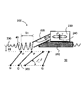
Referring to FIG. 5, there is shown an example of an ocean wave system
pursuant to the
present invention; the system is generally indicated by 200. The system 200 is
susceptible
to being deployed along coastlines, deployed as floating islands off-shore,
deployed as
peninsula, and/or disposed as floating bridges for coupling landmasses
together and for
synergistically also generating power. Moreover, the system 200 comprises at
least one
floating, seabed-supported or coastal-supported platform 210 bearing one or
more obliquely-
orientated air columns 220 in a manner akin to columns described in
aforementioned patent
no. NO 327593 (inventor: Geir Arne Solheim) hereby incorporated by reference.
The one or
more air columns 220 operate in a similar manner to those described in patent
no. NO
327593, namely ocean waves 40 interact with lower ends of the one or more air
columns 220
to compress and rarefy air cyclically in upper ends of the one or more columns
220.
Moreover, the one or more air columns 220 are coupled at their upper ends in
air
communication to one or more large-diameter air-propelled turbines 230.
Optionally, the one
or more turbines 230 are orientated with their one or more axes of rotation
240 disposed in
operation in a vertical direction as illustrated. At a front peripheral edge
of the platform 210 is
included, in operation in a submerged state, at least one underwater planar
baffle 300 as
illustrated in FIG. 5. Optionally, the planar baffle 300 is in substantially
tilted orientation as
illustrated, namely subtending an angle /3 relative to a nominal surface plane
of the ocean 30.
As an alternative, or addition, to utilizing the baffle 300, other types of
element can be
employed, for example tubular elements, disc-like elements, spherical
elements,
hemispherical elements, curved elements. Beneficially, the one or more air
columns 220 are
tuned so that their natural resonant frequency of wave motion therein, for
example a function
CA 02803483 2012-12-20
WO 2011/162615 PCT/N02011/000175
-15-
of a diameter or cross-sectional area of the one or more columns 220, is
substantially
matched to a frequency of incoming ocean waves 40 received at the one or more
columns
220 so that they most efficiently covert energy present in the incoming ocean
waves to
useable energy in the system 200. Substantial matching is, for example, to be
construed to
be within -6 dB points of resonance, and more preferably within -3 dB points
of resonance.
Optionally, the one or more columns 220 are actively tuned so that their
natural frequencies
of waves therein are matched in operation to incoming ocean waves 40 received
thereat;
such tuning is for example achieved by including actuated panel baffles within
the one or
more columns 220. Optionally, the one or more columns 220 are manufactured to
have
mutually different natural frequencies of wave motion therein, so that at
least certain of the
one or more columns 220 will optimally match in their tuning to the incoming
ocean waves.
In operation, when the system 200 is implemented as a floating structure, the
one or more
turbines 230 beneficially function as gyroscopes, namely flywheels, in
operation when
rotating to maintain the platform 210 angularly stable, namely by way of
Coriolis forces; such
stability is highly beneficially to render the platform 210 robust in storm
conditions as well as
ensuring that lower ends of the one or more columns 220 are correctly
orientated and
positioned in respect of an upper surface 330 of the ocean environment 30. The
planar
baffle 300 serves two synergistic purposes:
(i) a first purpose is to stabilize the platform 210. in rough seas when
implemented as a
floating structure because at least a portion of the planar baffle 300 is
substantially
below an principal energy field of waves 40 propagating on the upper surface
330 of
the ocean environment 30; beneficially, the planar baffle 300 is below a 25%
attenuation level for a principal wavelength of waves propagating on the
surface 330
of the ocean environment 30;
(ii) a second purpose is to affect at a lower spatial level an energy field of
waves
propagating on the surface 330 of the ocean environment 30 to cause coherence
and
hence a tendency for the waves to increase in height towards a breaking state,
for
example as occurs near a beach as water shallows; such increase in coherence
resulting in greater wave amplitude greatly improves wave energy coupling into
the
one or more columns 220.
Optionally, the system 200 includes one or more planar baffles 300, and/or
alternative
elements as described in the foregoing, which are actuated for adjusting their
positions
relative to the platform 210 in operation as a function of ocean wave
amplitude and/or wave
principal wavelength. Ranges of adjustment for the one or more planar baffles
300 and/or
alternative elements will be described in greater detail later. Beneficially,
for reducing cost,
principal components of the system 200, for example walls of the one or more
columns 220
CA 02803483 2012-12-20
WO 2011/162615 PCT/N02011/000175
-16-
and of the platform 210, are constructed from reinforced marine-grade non-
porous concrete,
for example of a type as utilized in contemporary off-shore oil platforms.
Beneficially,
components parts of the system 200 are fabricated from marine-grade concrete
which is cast
in situ in an ocean environment, thereby avoiding a need to transport large
pre-fabricated
components.
The one or more turbines 230 are optionally coupled to electrical power
generators for
generating electricity for output from the system 200. Optionally, the one or
more turbines
230 include blades 400 operated by air pressure differences thereacross to
cause one or
more corresponding rotors 410 of the one or more turbines 230 to rotate in
operation as
illustrated in FIG. 6. Beneficially, the one or more turbines 230 are
implemented to include
coils 420 and/or magnets 430 so that functions of turbine and generator are
spatially
collocated; for example, peripheral regions of the blades 400 are equipped
with permanent
magnets 430 which are drawn peripherally past stationary coils 420 for
generating electrical
output from the system 200. Such simplicity of construction of the turbines
230 is capable of
providing enhanced operating reliability of the system 200 by way of fewer
moving parts.
Optionally, the one or more turbines 230 are supplied with compressed air via
a plenum,
namely an air reservoir, which is coupled via valves to a relatively large
number of the
columns 220, for example in excess of 20 columns, for avoiding pulsating
outputs from the
generator. Beneficially, wave motion within the large number of columns 220 is
asynchronous to reduce a tendency to generate pulsating output from the system
200 at a
frequency corresponding to wave 40 frequency. The system 200 pursuant to the
present
invention deployed in large scale in ocean environments 30 is capable of
generating
electrical power at highly competitive costs, thereby potentially addressing
the present World
shortfall in energy associated with "peak oil", without adding to atmospheric
carbon dioxide
when in operation. Moreover, being an electromechanical apparatus, the system
200 is not
capable of causing dangerous environmental pollution, for example as occurred
in Chernobyl
(Ukraine), Three Mile Island (Harrisburg)(USA), Fukushima (Japan) and
Sellafield
("Windscale") (United Kingdom). Present World power consumption from fossil
fuels is
estimated to be around 4 TeraWatts which can potentially, to a considerable
extent, be
supplied by the system 200 when deployed World-wide within ocean environments
30.
Beneficially, the system 200 does not cause pollution and generates electrical
energy in a
completely sustainable and clean manner. When implemented in a floating manner
off-
shore, the system 200 is potentially capable of withstanding tsunami
conditions which cause
damage only when reaching a coastal region, for example as occurred at
Fukushima (Japan)
in the year 2011. The system 200 is thus potentially far more robust in
comparison to
nuclear facilities deployed at vulnerable coastal locations.
CA 02803483 2012-12-20
WO 2011/162615 PCT/N02011/000175
-17-
Referring again to FIG. 5, the submerged planar baffle 300 has an upper extent
denoted by a
point P and has a lower extent Q which is optionally at a constant distance
from the point P.
Optionally, an extent of the planar baffle 300 is made dynamically alterable,
for example by
implementing the planar baffle 300 as a set of sheets of material disposed
mutually in
parallel in mutual contact, and which can mutually slide to provide the baffle
300 with variable
extent from the point P for providing an optimal impedance match between the
columns 220
and the waves propagating within the ocean environment 30. As illustrated in
FIG. 5, the
baffle 300 is provided with an actuator (not shown) for varying a distance S1
of the point P
with respect to a lower open end of the column 220. Moreover, an angle fl of
the baffle 300
is dynamically alterable to provide best matching of waves 40 to the column
220.
Furthermore, a depth S2 of the point P below the surface 330 of the ocean
environment 30 is
also susceptible to being altered dynamically. However, it must be appreciated
that the
system 200 includes several such columns 220 in a manner of a 2-dimensional
array, with
rows of columns 220 disposed in parallel and orthogonal to wavefronts of the
waves 40.
Optionally, the baffle 300 is capable of being curved in operation for
providing fine tuning of
the wave 40 matching to the columns 220.
Wave energy reflectors (WARE, TM of Havkraft AS) pursuant to the present
invention will
now be elucidated in further detail. WARE TM (Wave Reflector) is an apparatus
or
arrangement for reflecting wave energy upwards towards a surface region of an
ocean for
providing for enhanced energy pickoff performance. WARE, TM (Wave Reflector)
is
especially beneficially employed in combination with an ocean wave energy
system as
described in aforementioned granted patent no. NO 327593 (attributed to
inventor Geir Arne
Solheim). In operation, WARE TM (Wave Reflector) is an apparatus or
arrangement which
is mounted on a mooring arrangement and is disposed sub-sea directly under an
ocean
surface. WARE, TM (Wave Reflector) is a simple unitary construction with
moveable parts
which are manipulated by actuation to regulate a manner in which waves
propagate through
an ocean environment for being received by ocean wave energy systems for
generating
sustainable renewable energy.
WARE TM (Wave Reflector) is beneficially implemented as the one or more
planar baffles
300 of desirable breadth whose angle Q relative to horizontal and position S1,
S2 are
regulated in operation by associated actuator mechanisms in a manner as
illustrated in FIG.
5, and FIG. 7 to FIG. 9. Various strategies can be beneficially employed to
dispose the
WARE, TM (Wave Reflector), namely the planar baffle 300, in an optimal
position and
angle for enhancing power generation from ocean waves 40 achieved by the
system 200.
CA 02803483 2012-12-20
WO 2011/162615 PCT/N02011/000175
-18-
WARE, TM (Wave Reflector) is beneficially adjusted and steered at two points
P, Q on the
upper and lower portions of the baffle 300 respectively in a mutually
independent manner to
provide independent adjustment of a position S1 and an angle 8 of the baffle
300.
Optionally, a depth S2 of the baffle 300 as defined by its upper extent P is
also adjustable for
providing optimal matching of ocean waves to the one or more columns 220 of
the system
200. WARE, TM (Wave Reflector) is capable of operating in a simple manner by
using
simple mechanisms, for example on rails with actuation force being coupled by
wires and/or
belts and/pr chains from actuators 500 as illustrated in FIG. 9. In an
optional implementation,
the planar baffle 300 is attached at its upper point P, and its lower end Q is
freely adjustable
as illustrated in FIG. 8.
Referring to FIG. 10, the system 200 is beneficially constructed onto a
platform 520
supported by one or more pillars 530 onto sea-bed foundations 540;
alternatively, the system
200 can be implemented as a floating structure. The system 200 includes one or
more rows
of columns 220 whose lower open ends face towards a spatial region in which
one or more
planar baffles 300 are included, wherein the one or more planar baffles 300
are actuated as
aforementioned to couple ocean waves 40 most efficiently from the ocean
environment 30 to
the one or columns 220.
The WARE, TM (Wave Reflector), namely the planar baffles 300 and their
associated
actuator arrangements, optionally each have a spatial planar extent in a range
of 10 metres x
2 metres to 30 metres x 8 metres. More optionally, the spatial planar extent
of each baffle
300 is substantially 20 metres x 5 metres. The planar baffles 300 are each
adapted to a
typical ocean wave 40 wavelength for being capable of considerably influencing
an energy
field of such waves. When the planar baffles 300 are orientated in a manner
such that their
major surface planes are parallel to an upper surface of the ocean environment
30, the
planar baffles 300 being submerged, the ocean waves 40 are most strongly
affected by the
baffles 300. Conversely, when the baffles 300 are in a vertical orientation
such that their
major surface planes are orthogonal to the upper surface of the ocean
environment 30, the
ocean waves 40 are least affected. Optionally, the distance S2 can be
increased to reduce
an effect of the baffles 300, and reduced to enhance an effect of the baffles
300. Optionally,
the baffles 300 are adjustable up to 15% of their breadth in position, namely
the distances
S1, S2, and can be adjusted in a range of 180 , namely the angle ft
The WARE, TM (Wave Reflector) represents an innovation in respect ocean wave
systems
operable to extract energy from ocean waves. In use, the wave reflector
implemented by
CA 02803483 2012-12-20
WO 2011/162615 PCT/N02011/000175
-19-
way of the baffles 300 and their associate actuators and control system, is
operable to
provide one or more of the following functions:
(a) to provide better matching of the waves 40 to the columns 220 to
pressurize air within
a plenum, namely reservoir, coupled via valves to the columns 220, wherein the
plenum is coupled to the turbine 230;
(b) to provide a manner of power control to cause transmission or reflection
of ocean
waves 40 in respect of the system 200, thereby assisting to regulate power
output
from the system 200 and/or to assist the system 200 to withstand severe
weather
conditions (for example hurricane conditions); and
(c) to provide the system 200 with greater stability in adverse weather
conditions when
implemented as a floating structure, on account of ocean environment water in
a
region of the end Q being relative tranquil during storm conditions.
Wave motion at a surface of the ocean environment 30 can be complex with waves
of
several different wavelengths being temporally concurrently present. Moreover,
ocean wave
characteristics can change dynamically which would cause fluctuations in
output from the
system 200 were it not for the baffles 300 and their associated actuators 500
and control
system 510 responding to modify the angle 8 and/or the distance S1 and/or the
distance S2
in temporal dynamic response to changes in ocean wave conditions. Actuation of
the
baffles 300 is beneficially achieved by employing rails for providing
adjustment of the
distance S1, and by employing wires for adjusting the angle by way of the
lower region Q
being free to move whereas the upper region P is arranged to pivot as
illustrated in FIG. 8.
The baffles 300 and their associated actuators are susceptible to being
controlled in various
manners during operation.
In a first method, motion of the waves 40 within the ocean environment 30 is
monitored from
the system 200 using optical image apparatus, for example telescopic cameras,
which
determines a frequency spectrum of the waves 40, for example in a similar
manner as
illustrated in FIG. 4A and FIG. 4B. A computer model of the system 200 then
computes in
real time how the system 200 will behave to the observed waves 40 approaching
the system
200 for various positions of the baffles 300 disposed near open mouths of the
columns 220
for providing a desired output. When an optimal position of the baffles 300 is
computed, the
control system then adjusts positions of the baffles 300 so that they are in
an optimal position
when the observed waves 40 arrive at the system 200 for coupling into the
columns 220 in a
desired manner. The computer model can be an explicit numerical model of the
system 200.
Alternatively, the computer model can be implemented as a neural network,
wherein the
control system has learnt by controlling operation of the system 200 and/or by
simulation an
CA 02803483 2012-12-20
WO 2011/162615 PCT/N02011/000175
-20-
optimal adjustment of the baffles 300 when the control system is presented
with different
views of the ocean waves 40. The control system can be implemented in
electronic
hardware or by employing computer software products stored on machine-readable
data
storage media and executing upon computing hardware. As an alternative or
addition to
employing an optical image apparatus, one or more monitoring buoys can be
placed at a
distance from the baffles 300 to sense wave spectral characteristics, the one
or more buoys
700 being operable to convey their sensed data to the system 200 via a
wireless
communication link 710. The one or more buoys 700 are beneficially each
equipped with an
inertial sensor unit comprising accelerators and, optionally, gyroscopic
devices for enabling
the one or more buoys 700 to sense wave 40 height and frequency; information
describing
sensed wave 40 height and frequency is conveyed by wireless to the system 200
before the
sensed waves 40 are received at the system 200, thereby providing an
opportunity for the
control system to adjust the baffles 300 to an optimal position to receive the
sensed waves
40. By such a control method, it is possible to tune the system 200
dynamically in real time
to provide a best performance.
In a second method, namely quasi-steady state control, the control system for
the baffles 300
applies small perturbations in angle/3 and/or one or more of the positions S1,
S2 of the
baffles 300 when in operation when at least partially matching waves 40 to the
columns 220.
The control system, at any given point in time, determines whether or not an
applied
perturbation causes a further improvement in operations of the system 200, and
continues to
apply subsequent such small perturbations until the system 200 is operating as
optimally as
it is capable of functioning in any given condition of the ocean environment
30. By such a
control method, it is possible to tune the system 200 dynamically in real time
to provide a
best performance. Optionally, a combination of the first and second methods is
employed.
Optionally, the system 200 is employed both as an ocean wave power generating
facility and
also as a coastal erosion defence. Aquaculture facilities 800 are beneficially
spatially
collocated with the system 200, for example in regions of calmer water created
by operation
of the system 200. Such aquaculture is beneficially implemented in fish cages,
such that the
fish cages can be submerged in calmer deeper water substantially beneath the
system 200
in an event of severe storm conditions for protection; when submerged in
calmer deeper
water, artificial aeration is beneficially provided to the submerged fish
cages. The system
200 is of benefit in that natural fish, for example krill, will naturally seek
protection in calmer
water that the system 200 creates in its wake, namely in a region of ocean
between the
system 200 and land 600. This creates a calm environment for especially
productive fishing
using fish boats. The aquaculture facilities 800 also have an enormous
advantage in that
CA 02803483 2012-12-20
WO 2011/162615 PCT/N02011/000175
-21-
parasites and pollution experienced in intensive fjord-based aquaculture is
less of a problem
in open ocean environments. Moreover, boats beneficially moor with the system
200 when
servicing the aquaculture facilities 800, thereby enhancing safety
considerably in commercial
fishing activities.
It will be appreciated that the system 200 is capable of being fixedly mounted
to an ocean
floor, namely seabed, of the ocean environment 30, for example as illustrated
in FIG. 10 and
FIG. 11, or can be floating offshore and tethered via anchors to the ocean
floor. The anchors
are beneficially implemented by way of suction cups, seabed anchors fastened
into bore
holes pre-drilled into the ocean floor, and/or heavy hollow tanks which
synergistically
optionally function as compressed-air reservoirs, namely plenum, for the
columns 220 to
smooth out variations in compressed air flow provided from the columns 220 to
enable the
system 200 to deliver a more stable flow of energy. Optionally, as
aforementioned, the
system 200 is implemented as one or more floating island, or as a floating
peninsula coupled
at one end to land for coupling electrical cables from the generators 230 to
land 600.
Optionally, for example as illustrated in FIG. 12, the system 200 can be
implemented such
that it is able to rotate about a single pillar 530 and associated foundation
530, thereby
enabling the system 200 to adjust dynamically to changing wave 40 propagation
directions;
in such case, the system 200 is provided with an appropriate rotation control
arrangement
and. rotation actuators, and the system 200 is equipped with sensors, for
example optical
imaging sensors, for determining prevailing instantaneous wave propagating
direction. As an
alternative or addition to employing the electrical cables from the generators
230 to land 600,
the system 200 is beneficially operable to electrolyse sea water to generate
Hydrogen as fuel
which is piped to land 600 or periodically transported to land by boat;
internal combustion
engines are beneficially adapted to function on Hydrogen, and/or Hydrogen is
beneficially
oxidized in fuel cells for generating electrical power for transportation
purposes. Yet
alternatively, the system 200 includes apparatus for chemically converting
Carbon Dioxide
and sea water supplied to the system 200 to hydrocarbon compounds, for example
to
synthetic organic fuels for use in automobiles, in aircraft and in plastics
materials production;
the apparatus of chemically converting is provided with energy generated by
the system 200.
Referring next to FIG. 13, a modified version of the system 200 is indicated
generally by
1000. The system 1000 includes one or more wind turbines 1010. Optionally, the
one or
more wind turbines 1010 are disposed at least at spatial extremes of the
platform 520 as
illustrated to achieve an optimal stability for the platform 520.
Alternatively, the one or more
wind turbines 1010 are concentrated near a central portion of the platform 520
and a majority
of ballast (providing upward floatation force), when the platform 520 is
implemented as a
CA 02803483 2012-12-20
WO 2011/162615 PCT/N02011/000175
-22-
floating structure, is disposed at peripheral extremities of the platform 520
to provide best
floating stability for the system 1000. Optionally, the platform 520 is
implemented as a
generally rectilinear planar component in plan view; more optionally, a
leading edge of the
platform 520 facing towards the ocean environment 30 is inwardly curved as
illustrated for
assisting to concentrate ocean wave energy. Optionally, the platform 520 is
implemented to
have a "T-shaped or "Y"-shaped planar form in plan view. Optionally, as
illustrated, the one
or more wind turbines 1010 are implemented as conventional contemporary
nacelle-type
wind turbines, for example as contemporarily manufactured by companies such as
GE Wind
Energy Inc., Vestas AS and Gamesa SA.
Optionally, one or more of the wind turbines 1010 are implemented as vertical
axis wind
turbines, for example Darrieus-type vertical axis wind turbines. Such Darrieus-
type wind
turbines beneficially include two or more substantially vertical blades, for
example three
blades, alternatively utilize a helical wing arrangement. Darrieus-type wind
turbines are of an
advantage in that they do not need to be actively steered in a direction of
incoming wind,
namely are essentially very simple devices, namely a factor which is
susceptible to
enhancing their reliability of operation. Optionally, one or more of the wind
turbines 1010 are
implemented as a Darrieus-type wind turbine 1200 illustrated in FIG. 14. The
turbine 1200
includes a bearing mount 1220 supported by the platform 520. Moreover, the
mount 1220
includes a generator for generating useable energy for output from the system
1000. The
mount 1220 rotatably supports a circular base 1210 which forms a flywheel when
rotating in
operation; the flywheel when rotating generates Coriolis forces (gyroscopic
forces) which are
highly beneficial to assist to stabilize the platform 520 to resists angular
tilting thereof in
response to the ocean waves 40 acting thereupon. When implemented as Darrieus-
type
wind turbines, the turbines 1010 are beneficially implemented to rotate in a
mutually similar
rotation direction so that their Coriolis forces are mutually additive to
assist to stabilize the
platform 520; optionally, braking forces are applied to the turbines 1010
implemented as
Darrieus-type wind turbines in an event that they spontaneously attempt to
rotate in a
mutually incorrect rotation direction. The turbine 1200 includes a central
axial elongate
member 1230, and three turbine blades 1240A, 1240B, 1240C disposed at 120
angular
intervals at a radius from the elongate member 1230 and in a substantially
vertical
orientation. The blades 1240A, 1240B, 1240C are supported on elongate support
members
1250A, 1250B, 1250C respectively. Optionally, the elongate support members
1250A,
1250B, 1250C are pivotally mounted at their lower ends to pivot blocks 1260A,
1260B,
1260C respectively, wherein the blocks 1260A, 1260B, 1260C are supported at an
upper
peripheral edge of the circular base 1210. Optionally, the blocks 1260A,
1260B, 1260C are
integral to the circular base 1210. The elongate support members 1250A, 1250B,
1250C are
CA 02803483 2012-12-20
WO 2011/162615 PCT/N02011/000175
-23-
beneficially pivotally swung from a substantially vertical position to a
substantially horizontal
position for maintenance, or for providing the blades 1240A, 1240B, 1240C with
protection in
extremely severe weather conditions; optionally, the elongate support members
1250A,
1250B, 1250C are winched into position to abut and couple to radial support
members
1270A, 1270B, 1270C respectively. The turbine 1210 is of benefit in that a
substantial part
of its mass is near a height of the platform 520, therefore enhancing
operating stability of the
system 1000. Moreover, the generator of the turbine 1200 is easily accessible
at a height of
the platform for maintenance and repair; this is in contradistinction to the
nacelle-type wind
turbines illustrated in FIG. 13 which include their gear boxes and generators
in a relatively
inaccessible manner at a top of a tower member. As an alternative to pivoting
the elongate
members 1250, their blades 1240 are slid down the elongate members 1250 for
protection
and or maintenance, and slid up the elongate members 1250 for operation.
The system 1200 is capable of providing numerous synergistic benefits in terms
of power
production and aquaculture in comparison to convention renewable energy
systems, for
example contemporary nacelle-type wind turbine parks. The system 1200 is not
to be
compared with other types of renewable energy systems, for example
hydroelectric power
systems, because the system 1200 provides synergistic benefits of coastal
protection and
aquaculture as well as power generation. Such synergy greatly improves the
commercial
viability of the system 1200 in comparison to alternative types of renewable
energy systems,
potentially to a level competitive in comparison to contemporary nuclear and
fossil fuel power
generating facilities, but devoid of waste products and pollution arising from
power
generation. The present invention is thus a considerable advance and
improvement on
known contemporary renewable energy systems.
In the forgoing, reference is made to a natural frequency of oscillation of
water within an air
column. From theoretical analysis, a natural period for such oscillation is
given by Equation
6 (Eq. 6):
Cd + D cos(a)J
Tõ = 2~r Eq. 6
gsin(a)
wherein
Tõ = natural period of oscillation;
Jr = 3.14159;
CA 02803483 2012-12-20
WO 2011/162615 PCT/N02011/000175
-24-
d = depth from mean sea level (MSL) to a middle of the hollow column;
D = inner diameter of the hollow column;
g = gravitational acceleration, 9.81 m/s2; and
a = an inclination angle of the column, wherein a= 90 denotes a vertical
column, and a
= 0 denotes a horizontal column
From the natural period T,,, the natural frequency fõ is readily computed from
Equation 7 (Eq.
7):
fõ= Eq.7
TR
From Equations 6 and 7 (Eq. 6 and Eq. 7), it will be appreciated, pursuant to
the present
invention, that tuning of the column is achievable by adjusting or setting one
of more of:
(i) the depth d by way of ballasting and/or actuating the hollow column up or
down
relative to the mean sea level (MSL);
(ii) varying the inner diameter D of the column; and
(iii) adjusting the inclination angle a of the column.
Such adjustments are executed in ocean wave energy systems pursuant to the
present
invention.
In the foregoing, it will be appreciated that air compression occurring in
operation within the
one or more air columns 220 is cyclical in nature in response to ocean waves
40 acting upon
the one or more air columns 220 in operation. In order to generate a useful
air pressure
difference driving the one or more turbines 230, it is desirable that the one
or more columns
220 be selectively in air communication with the one or more turbines 230 when
air
pressures within the one or more columns 220 are capable of most effectively
driving the one
or more turbines 230, namely have a greatest pressure difference therein
relative to ambient
air pressure. Such selective air communication is susceptible to being
achieved in several
different manners in respect of the present invention. However, certain
implementations for
selective air communication are especially useful, for example as illustrated
in FIG. 15A, Fig.
15B and FIG. 16. The system 200 potentially includes a relatively large number
of columns
220, for example several hundred such columns 220, for example for achieving
generating
performances up to ten's of MW, eventually up towards GW class when the system
200 is
used as a safe environmentally-friendly alternative to nuclear facilities. In
operation, phases
of respective ocean waves 40 within the columns 220 will be mutually
different. It is thus
CA 02803483 2012-12-20
WO 2011/162615 PCT/N02011/000175
-25-
highly desirable that each column 220, or groups comprising spatially
neighbouring columns
220 which experience in operation similar wave phases therein, be furnished
with a valve
arrangement that selectively couples the column 220 into air communication
with the one or
more turbines 230, for example via one or more air reservoirs, namely a plenum
arrangement, for dampening out temporal pressure variations in compressed air
supply
provided to the one or more turbines 230. The valve arrangement is required to
be
inexpensive, be capable of performing millions of operations before needing
servicing or
replacement, be resistance to corrosion, be robust, and be capable of
providing a tight air
seal despite a risk of marine growth occurring during prolonged periods of
operation. Such
requirements place severe demands on a manner in which the valve arrangement
is
implemented. However, the present invention provides a synergistically
beneficially solution
to these technical constraints as will be elucidated below.
The inventor has appreciated that interfaces between certain materials, for
example an
interface between silica glass and polytetrafluoroethylene (PTFE) plastics
material, can be
lubricated by aqueous solution, for example sea water. Moreover, such
materials are not
susceptible to corrosion in saline environments and are resistant to marine
growth occurring
thereupon. Such interfaces in the presence of water form a low-friction
electrostatic bearing
at their mutual contact surfaces, wherein the silica glass is strongly
hydrophilic, whereas the
PTFE is strongly hydrophobic. Moreover, the PTFE plastics material is flexibly
compliant
and eventually polishes to conform with its abutting polished silica glass
surface to provide a
very effective air seal whilst synergistically also being a low-friction
bearing surface.
Furthermore, both silica glass and PTFE are mechanically strong materials
which can
withstand considerable forces and wear, for example pressure shocks from waves
in the
columns 220. Air valves for the one or more columns 220 are beneficially
implemented by
employing such silica glass and PTFE plastics materials or similar, wherein
opening and
closing of the air valves is achieved by a sliding movement, for example
implemented in a
linear movement as illustrated in FIG. 15A, or by a rotating movement as
illustrated in FIG.
15B. The sliding movement and rotating movements are operable to scrape away
any debris
collecting on the valves and also further prevent any build-up of marine
growth, namely they
exhibit a self-cleaning manner of operation. Although silica glass and PTFE
plastics
materials are described for use in the air valves, it will be appreciated that
other types of
glass and ceramics materials may alternatively be employed for implementing
the air valves,
and similarly other types of halogenated plastics materials may also be
employed for
implementing the air valves.
CA 02803483 2012-12-20
WO 2011/162615 PCT/N02011/000175
-26-
Referring to FIG. 15A, an air valve is indicated generally by 2000. The valve
2000 includes a
first plate 2010 and a second plate 2020, wherein the plates 2010, 2020 are
optionally
fabricated from mutually different materials, for example ground silica glass
and PTFE
plastics materials. The plates 2010, 2020 include solid regions 2040, 2060,
and one or more
apertures 2050, 2070 respectively, for example an array of apertures. The
plates 2010,
2020 are operable to be slid laterally, as denoted by 2030, in response to an
actuation force
being applied from an actuation arrangement, for example from an
electromagnetic solenoid,
a linear motor, a hydraulic ram, a pneumatic ram or similar. In a first state
M1, namely a
blocking "CLOSED" state, the one or more apertures 2050, 2070 of the plates
2010, 2020
respectively are mutually misaligned so that the valve 2000 prevents to air
flow therethrough.
In a second state M2, namely an open "OPEN" state, the one or more apertures
2050, 2070
of the plates 2010, 2020 respectively are mutually aligned so that the valve
2000 allows rapid
airflow therethrough, namely is capable of exhibiting a relatively low air
flow resistance
therethrough. Optionally, the second plate 2020 is included between two first
plates 2010 as
illustrated to form a stack of plates which are kept together by a compliant
force having a
direction substantially orthogonal to a plane of the plates 2010, 2020; such
compliant force
ensures that the valve 200 continues to be able to provide a tight seal as the
plates 2010,
2020 polish and wear in operation. Optionally, there are included multiple
first plates 2010
and multiple second plates 2020 in a sandwich-type arrangement; such a
sandwich-type
construction is especially favourable because a single actuator can be
employed and the
multiple plates 2010, 2020 ensure a high reliability of blocking
characteristic and an
enhanced robustness to pressure shocks.
When the plates 2010, 2020 are to be fabricated from glass, for example from
melted-down
recycles glass bottles, a block of glass is cast with its apertures formed
also by casting,
followed by a grinding operation to form polished interfacing surfaces
thereon. When the
plates 2010 are fabricated from PTFE plastics materials or similar, a sheet of
PTFE plastics
material is cut to size and then one or more apertures formed therein, for
example by laser
cutting or by mechanical punching operations. Beneficially, the plates 2010
are fabricated
from silica glass, and the plate 2020 is fabricated from PTFE plastics
material or similar
halogenated plastics material; such an implementation is beneficial in that
the plate 2020
fabricated from PTFE plastics material is relatively lightweight, is capable
of surviving
repeated mechanical shocks when being shuttled back and forth between "OPEN"
and
"CLOSED" positions, and is flexibly compliant to provide a soft support of the
plates 2010
fabricated from silica glass to prevent them from shattering when subject to
shock forces. As
aforementioned, a further advantage of such an implementation is that the
silica glass can be
manufactured from recycled glass materials, for example from melted-down
recycled glass
CA 02803483 2012-12-20
WO 2011/162615 PCT/N02011/000175
-27-
bottles; glass is well known to be extremely strong and capable of containing
high pressure
differences, for example a vacuum as in cathode ray tubes (CRTs) and
thermionic electron
tubes.
Beneficially, the plates 2010, 2020 each include an array of apertures 2050,
2070
respectively, so that the plates 2010, 2020 only need to be moved a relatively
small
proportion of their spatial extent to switch the valve 2000 between its "OPEN"
and "CLOSED"
states. This potentially enables the valve 2000 to be switched very quickly,
namely actuated
between the states M1 and M2, for example within fractions of a second.
Moreover, the
array of apertures 2050, 2070 also ensures that the valve 2000 exhibits a low
flow resistance
to air passing therethrough when in its "OPEN" state allowing, effectively, a
rapid transfer of
energy from the columns 220 via the plenum arrangement to the one or more
turbines 230.
Referring to FIG. 15B, an alternative implementation of a valve is indicated
generally by
2500, for selectively coupling one or more columns 220, optionally via an air
reservoir,
namely the aforesaid plenum arrangement, to the one or more turbines 230. The
valve 2500
is operable between its first state M1, namely "CLOSED" state for blocking air
flow
therethrough, and its second state M2, namely "OPEN" open state for passing
air flow
therethrough, by way of a rotational motion as illustrated. Electric motors,
hydraulic
rotational motors, pneumatics rotational motors, linear actuators and similar
can be used to
cause the rotational motion as illustrated about a rotational axis 2530. The
valve 2500
comprises a first plate 2510 including solid regions 2540 and one or more
apertures 2550,
and a second plate 2520 also including solid regions 2560 and one or more
apertures 2570.
In the first state M1, at least one of the plates 2510, 2520 is mutually
rotated so that their
apertures 2550, 2570 respectively are mutually non-overlapping, so that the
valve 2500 is
operable to prevent airflow therethrough. In the second state M2, at least one
of the plates
2510, 2520 are mutually rotated so that their apertures 2550, 2570
respectively are mutually
aligned, so that the valve 2500 is operable to permit airflow therethrough.
Optionally, an
additional plate 2510 is provided so that the plate 2520 is sandwiched between
two plates
2510 for mechanical support. Optionally, several plates 2510 and several
plates 2520 are
included spatially alternately in a sandwich-type arrangement and operated by
a single
actuator to provide an especially effective blocking to air flow therethrough
in the "CLOSED"
state and a high degree of reliability of blocking air flow. The plates 2510,
2520 are
beneficially fabricated from silica glass and PTFE plastic materials or
similar as elucidated in
the foregoing, which are susceptible to being lubricated by aqueous solution,
for example, by
spray or dampness from the ocean environment 30; for example, the plate 2520
is
beneficially fabricated from PTFE plastics material, and the plates 2510 are
fabricated from
CA 02803483 2012-12-20
WO 2011/162615 PCT/N02011/000175
-28-
silica glass. In a similar manner to the aforesaid valve 2000, rotational
motion in the valve
2500 results in polished air-sealing surfaces being formed at interfaces
between the plates
2510, 2510 and prevents build-up of any marine growth by way of self-cleaning
action during
actuation.
Operation of the valves 2000, 2500 when implementing the system 200 will now
be
described with reference to FIG. 16 and FIG. 17 to provide a system indicated
generally by
3000. When waves 40 are oscillating within the columns 220, for example in a
resonant
manner as elucidated in the foregoing, both rarefactions and compressions of
air occur at an
upper spatial region of the columns 220. When there are many columns 220 in
the system
3000, and the system 3000 has considerable spatial extent, for example 500
metres to
several kilometres wide orthogonal to a predominant direction of wave 40
propagation in the
ocean environment 30, wave 40 motions in the columns 220 are not necessarily
temporally
synchronized. In consequence, each column 220, or groups of spatially adjacent
columns
220 enjoying substantially mutually synchronous wave motions therein, are
provided with an
arrangement as illustrated in FIG. 16. The system 3000 includes the
aforementioned one or
more turbines 230 provided with compressed air from a high-pressure reservoir
3010,
namely high-pressure plenum arrangement, and provided with an air output sink
via a low-
pressure reservoir 3020, namely low-pressure plenum arrangement. In operation,
it is
desirable that the columns 220 only selectively contribute compressed air to
the high-
pressure reservoir 3010 when pressures at upper regions of the columns 220
momentarily
exceed a pressure within the high-pressure reservoir 3010. Similarly, in
operation, it is
desirable that the columns 220 only selectively receive output sink air when
pressure at
upper regions of the columns 220 momentarily is lower than a pressure within
the low-
pressure reservoir 3020. Such a manner of operation provides a greatest
pressure
difference between the reservoirs 3010, 3020 and hence a greatest differential
operating
pressure across the one or more turbines 230, thereby improving their
operating efficiency
for electrical power generation.
The aforesaid reservoirs 3010, 3020 are beneficially coupled to each column
220, or group of
such spatially adjacent columns 220, via valves, for example implemented as
one or more of
the valves 2000, 2500. Each column 220, or group of such spatially adjacent
columns 220,
is provided with a pressure sensor for measuring an instantaneous pressure P1
within the
column 220. The high-pressure reservoir 3010 includes a pressure sensor for
measuring an
instantaneous pressure P2 within the high-pressure reservoir 3010. Moreover,
the low-
pressure reservoir 3020 includes a pressure sensor for measuring an
instantaneous
pressure P3 within the low-pressure reservoir 3020. The valve 2000, 2500
employed for
CA 02803483 2012-12-20
WO 2011/162615 PCT/N02011/000175
-29-
coupling the column 220 to the high-pressure reservoir 3010, namely "inlet
valve", is
provided spatially locally thereto with an air flow sensor for measuring an
instantaneous air
flow FV1 and air-flow direction through the valve 2000, 2500 from the column
220 into the
high-pressure reservoir 3010. Similarly, the valve 2000, 2500 coupling the
column 220 to
the low-pressure reservoir 3020, namely the "outlet valve", is provided
spatially locally
thereto with an air flow sensor for measuring an instantaneous air flow FV2
and air-flow
direction through the valve 2000, 2500 from the low-pressure reservoir 2010
into the column
220. The system 3000 includes a control unit 3030 for receiving signals
corresponding to the
pressures P1, P2, P2, and the flow rates FV1, FV2 and their respective flow
directions.
Moreover, the control unit 3030 includes outputs VT1, VT2 for controlling
actuators of the
valves 2000, 2500 coupling to reservoirs 3010, 3020 as illustrated for
switching them
between their aforesaid "CLOSED" and "OPEN" states. The control unit 3030
beneficially
includes computing hardware which is operable to execute one or more software
products
recorded on machine-readable data storage media for performing its valve-
controlling
operations.
Operation of the system 3000 will now be described with reference to FIG. 15A,
FIG. 15B,
FIG. 16 and FIG. 17. The waves 40 cause cyclical pressurizations and
rarefactions to occur
within the upper region of the column 220. Beneficially, the dimensions of the
column 220
and its height relative to the ocean environment 30 are tuned to a wavelength
and thus
periodicity of the waves 40, namely is capable of performing as a tuned air
column. For
convenience, as aforementioned, the valve 2000, 2500 coupling from the column
220 to the
high-pressure reservoir 3010 will be referred to as being an "inlet valve",
and the valve 2000,
2500 coupling from the column 220 to the low-pressure reservoir 3020 will be
referred to as
being an "outlet valve". The inlet and outlet valves are normally in a
"CLOSED" state,
namely a state M1 as illustrated in FIG. 15A and FIG. 15B to block air-flow
occurring
therethrough. The inlet valve is opened, namely switched into an "OPEN" state,
when the
pressure P1 exceeds the pressure P2. Moreover, the outlet valve is opened,
namely
switched into an "OPEN" state, when the pressure P1 is lower than the pressure
P3. The
control unit 3030 is operable to monitor airflow rates FV1, FV2 and associated
air-flow
directions through the inlet and outlet valves respectively immediately after
these valves are
switched from their "CLOSED" state to their "OPEN" state; the air flow rates
are initially
higher and then diminish to approximately zero flow rate and eventually will
flow in a reverse
direction unless flow is hindered by the valves 2000, 2500. When one or more
of the flow
rates FV1, FV2 diminish to within a threshold of zero flow rate or begin to
flow in a reverse
direction, the inlet and outlet valves as appropriate are closed to avoid
unnecessarily draining
the reservoirs 3010, 3020 of air pressure difference therein. In an event that
one or more of
CA 02803483 2012-12-20
WO 2011/162615 PCT/N02011/000175
-30-
the flow rates FV1, FV2 are greater than the threshold when the inlet and
outlet valves are in
their "CLOSED" state, or it is clear from the air-flow rate direction that any
of the valves are
draining the reservoirs 3010, 3020 unnecessarily, this is indicative of
potential failure of at
least one of the inlet valve and outlet valve and is detected by the control
unit 3030 as a fault
situation needing attention, for example at least one of the inlet and outlet
valves has
become worn or damaged. Optionally, the system 3000 is arranged such that the
reservoirs
3010, 3020 each include a hierarchy of small sub-reservoirs each provided with
isolation
valves 2000, 2500, so that failure of one valve 2000, 2500 of one column 220
of the system
3000 does not cause cessation of operation of the system 3000 as a whole, but
can be
accommodated by isolating faulty columns 220 and associated inlet and outlet
valves. Such
isolation in fault conditions is beneficially executed by the control unit
3030, although it is
anticipated that such failure would occur rarely on account of the robust and
durable nature
of the valves 2000, 2500 as described in the foregoing.
On account of the valves 2000, 2500 being actuated in operation in a plane
which is
orthogonal to a direction of forces applied to the valves 2000, 2500 by way of
rarefaction and
compression of air occurring within upper regions of the columns 220, and on
account of the
valves 2000, 2500 employing interfacing surfaces forming effectively a
polished electrostatic
bearing thereat, relatively little actuating power and thus actuating force is
required for
operating the valves 2000, 2500 of the system 200, 3000 between their "CLOSED"
and
"OPEN" states.
Referring to FIG. 17, a graph illustrating operation of the valve 2000 feeding
into the high-
pressure reservoir 3010 is indicated generally by 3500. An abscissa axis 3510
denotes
passing of time from left to right, and an ordinate axis 3520 denotes various
parameters
including increasing pressure from bottom to top, increasing flow rate from
bottom to top and
valve switching state from "CLOSED" to "OPEN".
STEP 1: Initially, at a time to, at a left-hand side of the graph 3500, a wave
40 enters a given
column 220 and causes the pressure P1 gradually to rise at a top region of the
column 220.
Already, a high initial pressure P2 has been established in the high-pressure
reservoir 3010.
The inlet valve 2000, 2500 is in an "CLOSED" state to prevent air-flow
therethrough.
STEP 2: When the pressure P1 exceeds the pressure P2 by a threshold amount at
a time t1,
the inlet valve 2000, 2500 is switched by actuation from its "CLOSED" state to
its "OPEN"
state to allow air-flow therethrough. Opening of the inlet valve 2000, 2500
causes the flow
rate FL1 to rise dramatically and then diminish as the pressure P1, P2
mutually equalize.
CA 02803483 2012-12-20
WO 2011/162615 PCT/N02011/000175
-31-
STEP 3: when the flow rate FL1 is within a threshold of zero or has just begun
to be
reversed, namely flow occurring back into the column 220, the inlet valve
2000, 2500 is
actuated to its "CLOSED" blocking state to prevent loss of air pressure from
the high-
pressure reservoir 3010 and to force the flow-rate FL1 to zero.
By resonance, the wave 40 in the column 220 causes rarefaction at the upper
region of the
column 220 and a corresponding cycle to aforesaid STEPS 1 to STEP 3 is
executed in
respect of the outlet valve 2000, 2500 coupling between the low-pressure
reservoir 3020 and
10" the column 220, except that pressures are negative and flow-rate from the
low-pressure
reservoir 3020 into the column 220 occurs. Control of actuators of the inlet
and outlet valves
2000, 2500 is performed from the aforesaid control unit 3030.
Beneficially, the valves 2000, 2500 with their associated pressure sensors and
directional air-
flow sensor are manufactured as a mass-produced standard valve unit.
Optionally, larger
diameter columns 220 of the system 200, 3000 are beneficially provided with
several such
standard valve units, whereas smaller-diameter columns 220 of the system 200,
3000 are
provided with merely a single such standard unit. On account of the columns
220 being
passive components, the active one or more turbines 230 are well protected
from the ocean
environment 30. The valves 2000, 2500 perform a useful function of protecting
the one or
more turbines 230 and are therefore an important part of the system 200, 3000.
It is
therefore highly desirable that the valves 2000, 2500, namely employed in
large numbers in
the system 200, 3000, exhibit high reliability when in operation, are easy to
service and
replace, and are of relatively low cost, for example made possible by mass-
production
methods, and potentially using recycled materials in their production in an
environmental
friendly manner.
In the foregoing, the two reservoirs 3010, 3020, as illustrated in FIG. 18A,
are operable to
receive compressed or rarefied air supplies from the one or more columns 220
via their
valves 2000, 2500 for supplying the one or more turbines 320 with an air flow
4000
therethrough for generating electrical power. Optionally, as illustrated in
FIG. 18B, the one or
more turbines 320 include multiple stages for enabling them to receive
compressed and
rarefied air from multiple reservoirs 3010, 3020, 4010, 4020 operating at
mutually different
pressures, for example +2p, +1p, -1p, -2p for the reservoirs 3010, 3020, 4010,
4020
respectively, wherein the turbine 320 includes at least three stages 4050A,
4050B, 4050C.
Optionally, in the system 200, 3000, when a given column 220 is unable to
develop sufficient
pressure to supply the reservoirs 3010, 3020, the given column 220 is
selectively coupled via
CA 02803483 2012-12-20
WO 2011/162615 PCT/N02011/000175
-32-
air valve switching networks to the other reservoirs 4010, 4020 operating at
lower excess
pressure or excess under pressure relative to ambient pressure in comparison
to the
reservoirs 3010, 3020. Such an arrangement is capable of improving total
energy production
from the system 200, 3000 even if some of its columns 220 are unable to
generate sufficient
pressure in operation for feeding air to and/or from the reservoirs 3010,
3020, but can
nevertheless contribute to energy production by feeding air supply via the
additional
reservoirs 4010, 4020 to the one or more turbines 320. Although two additional
reservoirs
4010, 4020 are described, it will be appreciated that there are optionally
employed many
more such additional reservoirs if necessary, for example operating at various
pressure
differences relative to ambient pressure.
Use of compressed air reservoirs 3010, 3020, 4010, 4020 in the system 200,
3000 provides
an advantage that a central turbine facility, including the one or more
turbines 320, can be
employed, wherein the one or more turbines 320 are optionally operated
synchronously in
respect of an alternating frequency of an electrical supply network to which
the system 200,
3000 is connected.. Alternatively, as illustrated in FIG. 1, each column 220
is provided with
its own associated turbine 4200. Such an approach results in the columns 220
being
capable of operating in a mutually entirely autonomous manner, such that other
columns 220
and their associated turbines 4200 are able to continue functioning in an
event of the
columns 220 developing a fault in operation.
In FIG. 19A, the column 220 is provided at its upper region with an associated
turbine 4210
which is provided with a local energy pickoff 4220, for example implemented
using direct
electromagnetic induction at a peripheral edge of the turbine 4210 whereat
movement
velocity is greatest in operation, and wherein the turbine 4210 is capable of
continuing to
rotate irrespective of flow direction therethrough; for example, a turbine as
described in
United States patent application no. US 2010/0209236A1 ("Impulse Turbine for
Use in Bi-
Directional Flows"; inventors - Christopher Freeman, Stephen Herring, Kevin
Banks) is
optionally employed for implementing the turbine 4210; United States patent
application no.
US 201010209236A1 is hereby incorporated by reference. Alternatively a form of
turbine as
described in a United States patent no. US 5, 642, 984 ("Helical Turbine
Assembly operable
under Multidirectional Fluid Flow for Power and Propulsion Systems"; inventor
Alexander M.
Gorlov), for example in a compact form as described in a granted United States
patent no.
US 5, 577, 882 ("Uni-directional Reaction Turbine operable under Reversible
Fluid Flow";
inventors Boris Istorik, louli Chpolianski, Alexander Gorlov) is employed for
implementing the
turbine 4200; United States patent no. US 5, 642, 984 and United States patent
no. US 5,
577, 882 are hereby incorporated by reference. Equivalent types of flat radial
turbines
CA 02803483 2012-12-20
WO 2011/162615 PCT/N02011/000175
-33-
operable to turn in a single direction in response to bi-directional air flow
therethrough are
optionally employed for implementing the turbine 4210.
Alternatively, where exceptionally high energy conversion efficiency is
required at the turbine
4210 and the turbine 4200 is required to be as compact as possible, the
turbine 4210 is
beneficially implemented using a radial rotor 4500 as illustrated in FIG. 19B
whose blades
4510 are actuated, or otherwise moveable, in response to a direction of air
flow through the
turbine 4210 to maintain the turbine 4210 rotating in a constant direction and
thereby
maintaining its rotational inertial when in operation. Optionally, the turbine
4200 is
implemented as illustrated in FIG. 19C wherein the turbine 4200 includes first
and second
radial rotatable planar components 4600A, 4600B with permanent magnets 4610 at
their
peripheral edge for providing direct electromagnetic energy pickoff via
peripheral pickup coils
4620A, 4620B. The planar components 4600A, 4600B are disposed axially at a
distance D
apart and are coupled together via, for example, radial vane elements 4630
having linearly-
slidable and rotatable coupling joints 4640 as illustrated. By preferentially
creating excess
drag on one of the components 4600A, 4600B relative to the other thereof, or
alternatively by
applying an electromagnetic torque preferentially to one of the components
4600A, 4600B
relative to the other during power extraction from the 4200, the vane elements
4630 are
dynamically flipped in pitch angle so that pulsating bi-direction flows of air
through the turbine
4200 is FIG. 19C are efficiently converted to electrical energy irrespective
of air flow direction
past the vane elements 4630. When starting up the turbine 4200 into rotation,
the pickup
coils 4620A, 4620B are beneficially energized so that the turbine 4200 is
operated briefly as
an electric stepper motor; once rotating, operation by alternating drag and/or
alternating
drive torque on the planar components 4600A, 4600B keeps the turbine 4200
rotating in
response to pulsating air flow therethrough.
Optionally, the vane elements 4630 are fabricated from a robust flexible
material, for
example from reinforced polyurethane which is capable of withstanding millions
of flexural
cycles and also being inert to corrosion in respect of saline water in the
ocean environment
30. Optionally, the vane elements 4630 are greater in lateral extent to the
axial distance D
between the planar components 4600A, 4600B so that the vane elements 4630 are
bent into
slight curvature and excite an abrupt flip motion when adapting to different
directions of air
flow through the turbine 4200. The turbine 4200 as illustrated in FIG 19C is
beneficial in that
it can be made with few moving parts and its control is implemented largely
electronically.
Determination of air flow directions within the columns 220 for purposes of
controlling the
pitch angles of the vane elements 4630 of their turbines 4200 is beneficially
implemented
using flow sensors, for example above the turbines 4200 and thereby remote
from the ocean
CA 02803483 2012-12-20
WO 2011/162615 PCT/N02011/000175
-34-
environment 30; such a flow direction sensor is, for example, implemented
using a pressure-
dropping orifice with two pressure sensor sensors to determine instantaneous
pressures at
upstream and downstream sides of the orifice; optionally, the orifice is a
part of the structure
of the column 220.
Optionally, the planar components 4600A, 4600B are temporarily locked together
in
operation, for example by applying a magnetic force thereto via a magnetic
clutch and/or
hydraulic clutch disposed between the the planar components 4600A, 4600B, once
their
vane elements 4630 have assumed a correct instantaneous pitch angle for coping
with a
given instantaneous flow of air through the turbine 4200; such locking can be
achieved, for
example, using electromagnets 4700 included on the planar components 4600A,
4600B
which are energized via electromagnetic power transfer to the components
4600A, 4600B to
attract the components 4600A, 4600B together so that they rotate as a single
unitary entity in
response to a given direction of pulsed air flow through the turbine 4200 and
for a
corresponding given pitch angle of the vane elements 4630. Optionally, the
turbine 4200 can
be deployed to include multiple rotors, namely to be multi-staged when large
amounts of
power are to extracted, for example from relatively larger columns 220
included in the system
200, 3000.
Although extraction of power from the columns 220 is described in the
foregoing based on air
being cyclically pressurized and rarefied in response to wave motion in the
columns 220, for
example resonant wave motion therein, it is optionally feasible pursuant to
the present
invention, to deploy at least a portion of the turbine 4200 at a bottom region
of the columns
220 to be directly acted upon by waves oscillating within the columns 220.
Optionally, it is
desirable that at least a portion of the turbine 4200 is then beneficially
retractable from the
columns 220 in adverse weather conditions to avoid damage being sustained by
the at least
one portion of the turbine 4200 deployed in the bottom region.
When the system 200, 1000, 3000 is implemented as a floating structure, it is
important that
it is firmly anchored in view of the forces acting upon it, especially when it
includes wind
turbines producing many 10's to 100 MWs of power, possibly even GW for large
installations. Thus, the system 200, 1000, 3000 beneficially is anchored by at
least one
anchor when employed in a floating configuration. More optionally, the system
200, 1000,
3000 is anchored at least at each of its four extreme corners. Suitable
anchoring
arrangements for the system 200, 1000, 3000 are known from off-shore oil
platform
structures, for example as described in United States patent no. US 7, 752,
989 B2 ("Deep
Water High Capacity Anchoring and Method of Operation thereof"; inventors -
Vladimir Paz,
CA 02803483 2012-12-20
WO 2011/162615 PCT/N02011/000175
-35-
Elisabeth Porto, Cipriano Mediros Jnr.; assignee - Petrobras) hereby
incorporated by
reference, and also described in United States patent no. US 3, 934, 528 B
("Means and
Methods for Anchoring of Offshore Tension Leg Platform"; inventors - Edward
Horton, John
Brewer, William Silcox, T.A. Hudson; assignee - Deep Oil Technology Inc.)
hereby
incorporated by reference.
In overview, the following anchoring arrangements are susceptible to being
optionally
employed for anchoring the system 200, 1000, 3000:
(i) via anchors secured into boreholes drilled into the seabed;
(ii) via buoyant steel-walled and/or concrete-walled hollow tanks towed into
position on
the ocean surface, then filled with water to sink then to the seabed, and then
filled
with a sand/adhesive binding agent fluid which then sets within the tanks so
that they
form anchors resting on the seabed, and wherein the tanks are coupled via
chains
and/or cables to floating portions of the system 200, 1000, 3000; optionally,
the
adhesive binding agent is an epoxy or a marine-grade concrete; optionally, the
tanks
have a generally flat planar form so that at least one of their major surfaces
are
adapted to contact onto the seabed, and are further retained on the seabed by
depositing ballast stone thereupon; and
(iii) via use of one or more impact anchors which each comprise a massive
member with
a rounded or pointed front end and with vanes at its rear end, for example in
a form
akin to a torpedo, to which a mooring chain is also connected; during
installation,
each impact anchor is brought by ship to a location at which the anchor is to
be
deployed, the anchor is then released substantially vertically downwards so
that its
rounded or pointed front end impacts onto the seabed and penetrates into the
seabed, and the chain is then subjected to a non-vertical, namely lateral
force, to
draw the anchor a small distance backwards for embedding the vanes of the
anchor
into the seabed; such an approach is highly cost effective and rapid in
deployment,
but requires that the seabed is of such a geological composition that the
anchor is
capable through impact of embedding itself into the seabed; such an anchor is
beneficial when the seabed is geologically gravel, moraine, clay or similar
material
which can be displaced through impact; approaches (i) and (ii) above are
beneficially
employed when the seabed is of harder composition, for example granite.
Modifications to embodiments of the invention described in the foregoing are
possible without
departing from the scope of the invention as defined by the accompanying
claims.
Expressions such as "including", "comprising", "incorporating", "consisting
of', "have", "is"
used to describe and claim the present invention are intended to be construed
in a non-
CA 02803483 2012-12-20
WO 2011/162615 PCT/N02011/000175
-36-
exclusive manner, namely allowing for items, components or elements not
explicitly
described also to be present. Reference to the singular is also to be
construed to relate to
the plural. Numerals included within parentheses in the accompanying claims
are intended
to assist understanding of the claims and should not be construed in any way
to limit subject
matter claimed by these claims.