Note: Descriptions are shown in the official language in which they were submitted.
CA 02803547 2012-12-20
WO 2012/021180 PCT/US2011/031075
RETRACTABLE ENERGY ABSORBING WEBBING AND
METHOD OF MANUFACTURING SAME
BACKGROUND OF THE INVENTION
[0001] People at elevated positions above a floor or other relatively
lower surface
are at risk of falling and injury. For example, workers and other personnel
who have
occupations that require them to be at elevated positions, such as on
scaffolding, are at
risk of falling and injury. Safety harnesses are often worn to stop a person's
fall and
prevent or reduce injury.
[0002] Safety harnesses typically have a harness portion worn by the user
and a
tether or lanyard extending from the harness portion. The lanyard connects the
harness
portion to a secure structure. If a person falls from the elevated position
the safety
harness stops the person's fall when the lanyard is straightened.
[0003] A load limiter on a seat belt system can be worn to secure the
occupant of a
vehicle in the event of a sudden stop or collision to reduce the risk of
injury. If a person
is subjected to inertia due to a vehicle's sudden stop, the load limiter
limits the person's
forward movement when the load limiter is straightened.
[0004] Retractable lanyard devices are used in some fall protection
applications,
and retractable load limiter devices are used in some seat belt systems.
Retractable
lanyard devices are typically comprised of a flat webbing that is capable of
being received
within a retractor. Existing retractable lanyard devices have a mechanical
device in the
retractor to stop the fall (by preventing the webbing from advancing further
out of the
webbing) or to dissipate energy (by deforming metal). With typical retractable
lanyards
devices, however, the person's movement is stopped rather abruptly and the
person is
1
CA 02803547 2015-01-26
subjected to the shock force of the abrupt stop. Moreover, existing
retractable
lanyard devices are bulky, heavy, and costly.
[0005] Lanyards that attempt to absorb the shock of a person's fall are
known. Such lanyards, however, have bunched, accordion-type sections that
lengthen as energy is absorbed. These bunched sections prevent the use of an
energy absorbing webbing in a retractor, since a retractor requires the use of
a flat
webbing. Thus, a need exists for a retractable lanyard that absorbs energy.
SUMMARY
[0006] Certain versions generally pertain to energy absorbing webbings
and lanyards, and methods of making them. More specifically, some versions
pertain to an energy absorbing webbing that is generally flat and therefore
capable
of being received within a retractor.
[0007] One version provides a method of heat treating a webbing, the
webbing comprising a plurality of elongation yams and a plurality of ground
yams, comprising: (i) feeding the webbing through a first set of rollers at a
roll-in
speed; (ii) heat treating the webbing to adjust the relative lengths of the
plurality
of elongation yams and the plurality of ground yams; and (iii) feeding the
webbing through a second set of rollers at a roll-out speed, wherein the roll-
in
speed is up to approximately 65% greater than the roll-out speed.
[0008] Alternate or additional versions provide a method of heat treating
a
webbing, wherein the roll-in speed is greater than the roll-out speed.
[0009] Alternate or additional versions provide a method of heat treating
a
webbing, further comprising providing the webbing, wherein the plurality of
elongation yams of the webbing are partially oriented yarns.
2
CA 02803547 2012-12-20
WO 2012/021180 PCT/US2011/031075
[0010] Alternate or additional versions provide a method of heat treating
a
webbing, wherein the roll-in speed is up to approximately 65% greater than the
roll-out
speed.
[0011] Alternate or additional versions provide a method of heat treating
a
webbing, wherein the roll-in speed is approximately 10 yards per minute and
the roll-out
speed is approximately 8 yards per minute.
[0012] Alternate or additional versions provide a method of heat treating
a
webbing, further comprising cutting the webbing to a predetermined length and
then
positioning the webbing within a retractor.
[0013] Alternate or additional versions provide a webbing comprising a
plurality
of elongation yarns having a reduced length that is less than an original
length of the
plurality of elongation yarns, wherein the plurality of elongation yarns
comprise partially
oriented yarns; and a plurality of ground yarns having a length that is
approximately the
length of the original length of the plurality of elongation yarns; wherein
the webbing has
a length that is approximately equal to the reduced length of the plurality of
elongation
yarns; and wherein a weave-in of the plurality of ground yarns is greater than
a weave-in
of the plurality of elongation yarns.
[0014] Alternate or additional versions provide a webbing, wherein the
webbing is
generally flat.
[0015] Alternate or additional versions provide a webbing, wherein the
webbing
was processed via heat treatment.
[0016] Alternate or additional versions provide a webbing, wherein the
weave-in
of the plurality of the ground yarns and the weave-in of the plurality of the
elongation
yarns is substantially the same before the heat treatment.
3
CA 02803547 2012-12-20
WO 2012/021180 PCT/US2011/031075
[0017] Alternate or additional versions provide a webbing, wherein the
weave-in
of the plurality of the elongation yarns does not change substantially after
the heat
treatment.
[0018] Alternate or additional versions provide a webbing, wherein the
weave-in
of the plurality of ground yarns after the heat treatment is controlled by
varying the
duration of heat applied to the webbing.
[0019] Alternate or additional versions provide a webbing, wherein the
weave-in
of the plurality of ground yarns after the heat treatment is controlled by
varying the
speeds at which the webbing enters and exits the heat application.
[0020] Alternate or additional versions provide a webbing, wherein the
plurality of
elongation yarns extend throughout the webbing in a substantially warp
direction,
wherein the plurality of ground yarns extend throughout the webbing in a
substantially
warp direction, and further comprising a plurality of lateral yarns that
extend in a
substantially weft direction throughout the webbing.
[0021] Alternate or additional versions provide a webbing, wherein the
webbing is
capable of being used with a retractor.
[0022] Alternate or additional versions provide a webbing, wherein the
plurality of
elongation yarns and the plurality of ground yarns are interwoven together
throughout the
webbing in a warp direction.
[0023] Also provided is a method of manufacturing an energy absorbing
webbing,
comprising: (i) providing a plurality of partially oriented yarns comprising
an elongation
distance; (ii) providing a plurality of ground yarns; (iii) interweaving the
plurality of
ground yarns and the plurality of partially oriented yarns in a warp direction
along the
webbing; (iv) providing a plurality of lateral yarns in a weft direction along
the webbing;
4
CA 02803547 2012-12-20
WO 2012/021180 PCT/US2011/031075
(v) feeding the webbing through a first set of rollers at a roll-in speed;
(vi) applying heat
to the webbing as it is fed between the first set of rollers and a second set
of rollers to
adjust relative lengths of the plurality of elongation yarns and the plurality
of ground
yarns; and (vii) feeding the webbing through the second set of rollers at a
roll-out speed,
wherein the roll-in speed is different from the roll-out speed.
100241
Alternate or additional versions provide a method of manufacturing an
energy absorbing webbing, wherein the roll-in speed is up to approximately 65%
greater
than the roll-out speed.
[0025]
Alternate or additional versions provide a method of manufacturing an
energy absorbing webbing, wherein the roll-in speed is approximately 10 yards
per
minute and the roll-out speed is approximately 8 yards per minute.
[0026]
Alternate or additional versions provide a method of manufacturing an
energy absorbing webbing, further comprising positioning the webbing within a
retractor.
[0027]
Alternate or additional versions provide a method of manufacturing an
energy absorbing webbing, further comprising controlling the elongation
distance of the
partially oriented yarns by adjusting the roll-in speed relative to the roll-
out speed.
BRIEF DESCRIPTION OF THE FIGURES
[0028]
Figure 1 is a perspective view of a retractor in use with an energy
absorbing webbing according to one version.
[0029]
Figure 2 is a side cross-sectional view of the energy absorbing webbing
shown in Figure 1.
[0030]
Figure 3 is a top cut-away view of the energy absorbing webbing of
Figure 1.
CA 02803547 2012-12-20
WO 2012/021180 PCT/US2011/031075
[0031]
Figures 4 is an illustration of a heating process for manufacturing the
energy absorbing webbing of Figure 1 according to one version.
[0032]
Figure 5 is a pick diagram of a weaving pattern of the energy absorbing
webbing of Figure 1 according to one version.
[0033]
Figure 6 is a draw-in diagram of the energy absorbing webbing of Figure
1 according to one version.
DETAILED DESCRIPTION OF THE INVENTION
[0034]
Certain versions provide webbings 10 that are suitable for use in retractors,
such as retractor 12 shown in Figure 1. As illustrated in Figure 1, because
webbing 10 is
generally flat, webbing 10 is capable of being received within retractor 12
and of being
retracted in and out of retractor 12.
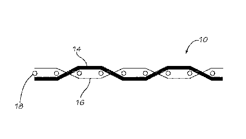
[0035] As
shown in Figure 2, webbing 10 comprises elongation yarns 14 and
ground yams 16 that are interwoven together. Ground yams 16 may be made of
nylon,
polyester, Kevlar, or any other high modulus, high tenacity yam or other
suitable
materials that are relatively higher strength and that do not shrink or shrink
substantially
less than the elongation yarns 14 during heat treatment. For example, the
ground yams
16 may have a strength of at least 5,000 pounds tensile strength. In some
versions, the
ground yams have a nominal breaking strength of greater than 5,400 pounds and,
in some
versions, have a nominal breaking strength exceeding 6,000 pounds, in
compliance with
29 C.F.R. 1926.104(d) (2008), American National Standards Institute ("ANSI")
Z335.1,
Canadian standard Z259.1.1 Class lA and 1B, European standard BS EN 355:2002,
and
Australian standard AN/NZS 1891.1.1995.
6
CA 02803547 2012-12-20
WO 2012/021180 PCT/US2011/031075
[0036] Elongation yams 14 are highly extensible yams and significantly
stretch
when placed under a tensile load. The elongation yarns 14 are one example of
an energy
absorbing member of the webbing 10. The elongation yams 14 may be partially
oriented
yams (POY) made of polymer materials such as polyester, but the elongation
yams 14
can be made from one or more suitable materials having high elongation
properties and
the ability to shrink in length substantially more than the ground yams, such
as during
heat treatment. In some versions, each of the elongation yams has a linear
density of
between approximately 300 denier and approximately 5,580 denier.
[0037] The elongation yams 14 have an elongation property that allows the
elongation yams 14 to stretch significantly under a predetermined tensile
force. The
elongation yarns 14 have this elongation property even after they are
subjected to a heat
treatment process. When the webbing 10 is placed under tensile load, the
elongation
yarns 14 stretch under tension and absorb some of the force or energy applied
to the
webbing 10. Accordingly, the elongation yarns 14 are a shock and energy
absorbing
member that provides a shock and energy absorbing feature.
[0038] Lateral yams 18 (also referred to as "weft" or "pick" yams) are
woven in a
weft direction across the webbing 10 to secure the elongation yarns 14 and the
ground
yams 16 laterally across the webbing 10. The lateral yams 18 may be
approximately
1,000 denier polyester yarns, or may bee industrial filament polyester, nylon,
Nomex,
Kevlar, or any other suitable yam.
[0039] Important properties of the elongation yams 14, which serve as the
energy
absorbing member, include some or all of high elongation, high shrinkage, and
high
shrink-force (the force produced during the shrinkage). The elongation yams 14
should
have sufficiently high elongation and load bearing properties under load to
absorb the
7
CA 02803547 2012-12-20
WO 2012/021180 PCT/US2011/031075
load energy so as to reduce shock to a person or other body in a sudden
deceleration state
such as that caused by a fall from a building, a parachute deploying, or an
impact due to
an automobile or aircraft accident. The webbings are sometimes adapted for use
where
dissipation of kinetic energy is required.
[0040] Webbings of the present invention may be formed on any desired
programmable loom, such as a needle loom. As described above, the webbing 10
includes elongation yarns 14, ground yarns 16, and lateral yarns 18. Figure 5
is a pick
diagram (also known as a chain diagram or cam draft) for the webbing 10. The
squares
along the x-axis represent the weaving path/throw of the lateral yarns 18, and
the y-axis
corresponds to groups of warp yarns (such as the elongation yarns 14 and the
ground
yarns 16). The pick diagram of Figure 5 shows an eight harness loom. When a
square is
shaded, it indicates that the harness corresponding to that square is lifted
as the lateral
yarn 18 is thrown across the loom.
[0041] The draw-in diagram of Figure 6 shows the placement of the
elongation
yarns 14 and the ground yarns 16 in harnesses to produce the webbing 10 of
Figures 2-3,
while the pick diagram of Figure 5 represents the action of the harnesses with
respect to
the lateral yarns 18 to create the webbing 10. The y-axis of the draw-in
diagram of Figure
6 represents the number of harnesses of a loom used to make the webbing 10. In
the
version shown, eight harnesses are used. In the version shown in Figure 6, the
bottom
four harnesses (harnesses 1-4) comprise the ground yarns 16 and the top four
harnesses
(harnesses 5-8) comprise the elongation yarns 14. The x-axis of Figure 6
represents the
yarns that are used to create the webbing 10, with row 26 showing the number
of times
each segment of the diagram repeats. For example, the first segment can repeat
any
number of times (nX), while the second segment repeats one time (1X). The
first column
8
CA 02803547 2012-12-20
WO 2012/021180 PCT/US2011/031075
of Figure 6 illustrates that the first yarn is in the first harness frame, and
the second yarn
is in the second harness frame. The webbing may be formed on any narrow fabric
loom,
including shuttle looms, or any other suitable loom.
[0042] In one version, the webbing 10 is a 4 foot by 1 and 3/8 inch nylon
structure
formed from approximately 248 Kevlar ground yarns (the ground yarns having a
linear
density of approximately 1,500 denier) and 90 elongation yarns (the elongation
yarns
being partially oriented yarns with a linear density of approximately 5580
denier).
[0043] One end of the webbing 10 is adapted to be attached to a hardware
component, such as a clip 11, metal clasp, harness, or seatbelt component,
while the other
end of the webbing 10 is situated within a retractor 12 (shown in Figure 1)
that is then
secured to a stable structure. In some uses, one end of the webbing 10 is
attached to a
harness and/or a clip for attachment to a child seat for use, for example, in
an automobile
or other vehicle.
[0044] The webbing 10 may be used as a deceleration device, to secure the
occupant of a vehicle against harmful movement that may result from a sudden
stop, or in
any other application where rapid human or other body deceleration may occur.
When
using the webbing as a fall protection device, one end of the webbing 10 is
securely
attached to a safety harness worn by a user. The opposite end of the webbing
10 is
securely attached to a fixed structure. If the user falls, the webbing 10
stops the person's
fall and reduces the shock felt by the person as the user is brought to a
controlled
deceleration. As the person falls, the webbing 10 straightens and the load of
the user is
applied to the webbing 10. The elongation yarns 14 stretch and absorb the
force of the
load applied to the webbing 10. As the elongation yarns 14 stretch, the
webbing 10
elongates. Where the webbing is used with a retractor, once the webbing 10 has
retracted
9
CA 02803547 2012-12-20
WO 2012/021180 PCT/US2011/031075
from the retractor 12, the webbing 10 stops the person from falling any
farther. The
shock of stopping the fall that would otherwise be felt by the falling person
is reduced or
cushioned by the energy-absorbing elongation yams 14.
[0045] Also provided is a process of manufacturing a generally flat
energy
absorbing woven webbing, such as webbing 10. In one version, webbing 10 is
subjected
to heat treatment to shrink the length of the elongation yarns 14. When the
webbing 10 is
subjected to heat treatment, the elongation yams 14 shrink in length while the
ground
yams 16 do not, resulting in a greater weave-in of the elongation yams 14 than
the
weave-in of the ground yams 16, where weave-in refers to the percentage
difference in
the length of the yam before weaving and the length of the webbing after
weaving. In
some versions, the ground yams 16 and the elongation yarns 14 both start with
an about
6% weave-in, such that the length of the elongation yams 14 and the ground
yarns 16 are
approximately 6% greater than the length of the webbing 10. In one version,
after the
webbing 10 is subjected to heat treatment, the length of the elongation yams
14 and the
length of the webbing 10 shrink by approximately 20%, while the length of the
ground
yarns 16 does not shrink. Thus, in this version, the elongation yams 14 will
remain at
around 6% weave-in while the ground yams will have around 26% weave-in. In
this
way, the relative lengths of the elongation yams 14 and the ground yams 16 are
automatically adjusted upon heat treatment. In one version, the webbing 10 is
heat
treated in a manner so that shrinkage of the elongation yarns 14 is
controlled.
[0046] For example, as illustrated in Figure 4, the webbing 10 may be
subjected to
a heat treating process to adjust the length of the yams of the webbing 10.
The heat
treatment apparatus of Figure 4 includes a first set of rollers 22, a second
set of rollers 20,
and a heat source 24 located between the first and second set of rollers.
Optionally, the
CA 02803547 2012-12-20
WO 2012/021180 PCT/US2011/031075
apparatus may also include controls and/or monitors to control and/or monitor
the feed
ratio between the two sets of rollers and/or the temperature of the heat
source.
[0047] In one version, the webbing 10 is fed through the first set of
rollers 22 to
the heat source 24, and out through the second set of rollers 20. As shown in
Figure 4,
the thickness of the webbing 10 changes as the webbing 10 is drawn from the
first set of
rollers 22 toward the second set of rollers 20. This is because the weave-in
of the ground
yams 16 increases as the webbing 10 is subjected to heat treatment. The amount
of
shrinkage of the elongation yarns 14 may be controlled by varying the
difference in speed
of the first set of rollers 22 and the speed of the second set of rollers 20.
This difference
in speed is referred to herein as the feed ratio of the rollers.
[0048] In one version, the speed at which the webbing 10 is fed through
the first
set of rollers 22 is greater than the speed at which the webbing 10 is fed
through the
second set of rollers 20. For example, in one version, the feed speed
associated with the
first set of rollers 22 is approximately 10 yards per minute, while the feed
speed
associated with the second set of rollers 20 is approximately 8 yards per
minute, for a
feed ratio of 20%. Since the webbing 10 is exiting the heat source 24 at a
speed that is
20% slower than the speed at which it entered the heat source 24, the webbing
10 is
subjected to an over feed ratio of 20% during heat treatment by the heat
source 24. In this
way, the elongation yams 14 will remain in tension between the first set of
rollers and the
second set of rollers and will be allowed to shrink approximately 20%, while
the other
materials (such as the ground yams 16) are gathered by the forces of the
elongation yarn
shrinkage, which results in a greater than 20% weave-in and a length reduction
of 20%.
Because the elongation yams 14 shrink when subjected to heat, while the ground
yams 16
do not have more than minimal shrinkage, the heat treatment process adjusts
the relative
11
CA 02803547 2012-12-20
WO 2012/021180 PCT/US2011/031075
length of the elongation yarns and the ground yams. In some versions, the
webbing 10 is
subjected to approximately less than 5 minutes of heat treatment at a
temperature of about
220 F.
[0049] The amount of elongation yams 14 in the webbing 10 may be varied
to
adjust the forces required to elongate the webbing 10. Similarly the shrinkage
of the
elongation yarns 14 in the webbing 10 may be varied to adjust the elongated
distance, or
the relative difference in length between the elongation yams 14 and the
ground yarns 16
of the webbing 10. As described above, the difference in length between the
two sets of
yams is caused by the difference in weave-in of the yams. Similarly, the feed
ratios
between the first set of rollers 20 and the second set of rollers 22 may be
varied to adjust
the forces required to elongate the webbing 10 and the elongation distance of
the webbing
10. Finally, the duration and amount of heat applied to the webbing 10 also
may be
varied to adjust the forces required to elongate the webbing 10 and the
elongation
distance of the webbing 10. This allows the properties of the webbing 10 to be
tailored to
the needs of the user and/or the application.
[0050] Various heat treating processes can be used to shrink the
elongation yarns
14. For example, a continuous oven may be used in an in-line, continuous
heating
process. The webbing 10 may be continuously woven and fed into the continuous
oven
for heat treatment. Another example of heat treatment is a batch process in
which
individual webbings are heat treated.
[0051] The webbing 10 may be designed to stop a falling person within 3.5
feet,
which is in compliance with 29 C.F.R. 1926.104(d) (2008). In this version, the
webbing
has a finished, ready-for-use length of about 6 feet. Prior to the heat
treatment, the
elongation yams 14 and the ground yams have a length of approximately 9.5
feet. After
12
CA 02803547 2012-12-20
WO 2012/021180 PCT/US2011/031075
heat treatment, the elongation yams 14 have a reduced length of about 6 feet
and the
ground yams 16 essentially retains their length of 9.5 feet. During use of the
webbing 10,
the elongation yarns 14 will stretch from about 6 feet to about 9.5 feet. When
the webbing
reaches the maximum 9.5 feet length, the webbing 10 stops the person's fall.
The
elongation yarns 14 absorb the energy of the fall and reduce the abrupt shock
to the
person when the webbing 10 stops the fall. In other versions, the webbing has
a finished,
ready-to-use length of about 4 feet. In one version having a ready-to-use
length of about
4 feet, the percentage of elongation yams to ground yams is approximately the
same,
however, the ratio of ground yams to elongation yams may vary depending on the
application. For example, more ground yarns to elongation yams may be required
for
higher strength applications, and more elongation yams to ground yarns may be
required
when a greater deployment force is required.
[0052] In another version of the present invention, a webbing has lengths
of the
elongation yams and the ground yarns to stop a falling person within about
11.75 feet.
The webbings, however, can be made in any desired length.
[0053] The webbings can be made of any suitable materials including, but
not
limited to, synthetic material yams woven to form the fabric structure.
[0054] Various changes and modifications to the webbings described herein
will
be apparent to those skilled in the art. Such changes and modifications can be
made
without departing from the spirit and scope of the invention and without
diminishing its
intended advantages. It is therefore intended that such changes and
modifications be
covered by the appended claims.
13