Note: Descriptions are shown in the official language in which they were submitted.
CA 02804072 2012-12-28
Process for thermal separation of a solution consisting of thermoplastic
polymer and
solvent
The invention relates to a process for the thermal separation of a solution
consisting of
thermoplastic polymer and solvent in which the solvent is heated under
pressure above the
critical point of the solvent and then decompressed into a vessel such that a
polymer-rich
phase and a low-polymer phase form, and wherein the polymer-rich phase is
supplied to a
second vessel.
Prior art
The specified invention represents an improvement of an existing process for
the thermal
separation of solvents from thermoplastic plastic materials, particularly
elastomers. US 3
726 843 discloses a process of this kind for the separation of an alcane,
particularly hexane,
from ethylene propylene diene monomer (EPDM) rubber. US 6 881 800 discloses a
similar
process with the difference that US 3 726 843 demonstrates the thermodynamic
states in
clearer detail. These processes are based on similar separation techniques of
polyethylene
or polypropylene from hexane, which have been in use on an industrial scale
for quite a
long period of time.
The fundamental advantage of the mentioned processes lies in the fact that,
during the
process steps, the polymer is always present in dissolved form, as a melt or
as a melt-type
paste. This is achieved by adding an alcane to the monomer mixture during the
polymerization step. Under a certain pressure, the monomers are polymerized in
hexane at
high degrees of conversion. The solution is then, in addition, possibly
decompressed and
heated indirectly to a certain temperature using a single or a plurality of
heat exchangers,
wherein the pressure must be selected such that the polymer always remains
nicely soluble
inside the solvent to avoid the formation of deposits in the heat exchanger.
In one example
on an industrial scale with hexane as a solvent, the necessary pressure is
approximately 50
to 80bar (gauge), the necessary temperature 220 to 240 C. The solvent now
undergoes
flashing inside a separator to achieve 20 to 30bar, wherein in the range
slightly above
critical a polymer-containing phase and a lighter, low-polymer phase form.
These phases
can then be separated by way of the difference in densities thereof. The
temperature
decrease in this pressure jump is minimal, because there is no enthalpy of
vaporization in
the above-critical range. The heat of the separated, low-polymer phase is
therefore usable
for heating the educt, which represents an essential advantage in terms of
process
1
CA 02804072 2012-12-28
technique. In a static flash vessel, the resulting polymer-rich phase
undergoes further
flashing to pressures between l bar (gauge) and 10bar (gauge), wherein the
pressure is
selected such that the flash is as complete as possible, while the polymer-
containing bottom,
however, remains in the form of a melt. The bottom can be supplied to a
degassing extruder
or kneader by means of a polymer pump or a valve, inside which any remaining
solvent and
monomer residues are removed in an absolute or partial vacuum.
For the above process to work, a sufficient enthalpy gradient must be present
such that,
after flashing, the polymer remains in the form of a melt inside the two
separators or the
drawing-in of the degasser. This aspect limits said process, as many polymers
have a
maximum temperature before thermal degradation sets in that is below a range
of 220 to
240 C. The use of a low-molecular solvent or of the monomer as a solvent is
conceivable
(in the presence of restricted solubility of the polymer in the monomer);
however, in this
case, the flash stage then results in temperatures that are far below the
melting point. This
problem, among others, is an issue with polystyrols or polybutadienes. While
polybutadiene
is not a thermoplastic material, it behaves, however, like a melt over a very
restricted
temperature range. In addition, with increasing molecular weight and
copolymers, the
melting point increases. This results in high torques, the formation of fine
particles and
reduced performance for higher-molecular EPDMs inside the degasser.
A further disadvantage of the existing process is the fact that the polymer-
rich bottom is
drawn from the flash container gravimetrically. If the viscosity of the bottom
is too high, the
pressure loss of the flow results in pressures that lead to strong cavitation
of the bottom.
This causes the transporting power of the supplied pump to be effectively
limited. In high-
molecular products, it was observed that the degasser downstream of the flash
vessel
suffers from operation-related problems, because the temperature of the bottom
from the
flash vessel drops due to the pressure jump, and the product tends to
solidify. The product
is then pulverized into particles by the shaft, which can plug up the exhaust
vapor lines. Due
to the fact that the heat transfer of the heating walls of the degasser is
especially poor with
high-molecular products, a considerable part of the volume is needed to heat
the polymer
particles above the plastification range at which point the shaft generates
sufficient torque
for heating the product by means of mechanical energy. This way, the degassing
capacity of
the degasser is substantially reduced, particularly in large-scale facilities,
because the ratio
of surface areas to volume becomes increasingly less favorable the larger the
equipment
size. Moreover, although the particles have a large surface, they do not
dynamically change
2
CA 02804072 2012-12-28
their surface areas, as is the case inside a melt. This further restricts the
degasification
capacity.
Object
It is the object of the present invention to improve a thermal separation
process for polymer
from solvent in high-molecular products and heat-sensitive polymers with
regard to a higher
molecular weight, less fine particle formation inside the degasser, higher
capacity, lower
residual contents of undesired volatile substances in the product of the
degasser and lower
energy consumption in comparison to existing processes.
Solution
The object is achieved in that
a) a pressure jump on entry into the second vessel leads to a thermal flash in
the
second vessel, the polymer part of the heavy phase rising to at least 70%,
especially
more than 80%; and
b) the resulting polymer-rich solution is supplied - especially distributed
over at least a
portion of the length of a stirrer shaft - which is within the same vessel
space and
which heats the polymer composition by mechanical kneading energy with the
effect
that the polymer content rises to >70%, particularly >90%.
In order to improve the aforementioned process, it is proposed according to
the invention
that the flash vessel be replaced with a mixer having a, for example,
horizontal kneader.
The flashed solution or suspension is distributed over the length of the
kneader upon a hot
bed and kneaded into the same. This can be achieved by means of a single feed
location or
a plurality of feed locations.
In terms of process technique, kneading a substance into a kneading bed is
referred to as
reconversion. Reconversion allows the stirring bed to have a higher
temperature or lower
solvent concentration than the supplied material flow. The energy that is
needed for the
additional evaporation capacity is supplied by means of the kneading energy
via the
dissipated power by the kneading shaft. The product space is, similarly to the
flash vessel it
3
CA 02804072 2012-12-28
replaces, operated under positive pressure in order to limit the speed of the
exhaust vapor
gas by means of the increased density.
However, due to the fact that the kneader is effectively able to discharge
even highly viscous
products by means of forced-transporting, the limitation as to discharge that
the existing
process suffers from (supplying the discharge pump) is omitted. The discharge
is
implemented by the geometry of the stirrer or kneader shaft and/or fixtures,
wherein the
same supply a discharge pump or discharge screw.
The discharge screw can have a pump arranged downstream thereto (for example,
a gear-
type pump) in order to be better able to control the discharge volume. The
kneading process
improves the separation of the bottom from the evaporated volatile materials,
because any
occurring foam is kneaded into the material and thereby mechanically
destroyed. The
solvent equilibrium of the bottom shifts in favor of a higher solid matter
content because of
the higher temperature. This way, the separation capacity of this process
stage is increased
and the load on the then-following degassing stage reduced.
Power absorption by the degassing stage is also reduced, because the product
is now
supplied with more excess heat. This excess heating results in more effective
degassing in
the entry area of the degasser and thus better degassing capacity with the
same energy
input. The higher feed temperature is selected such according to the invention
that the
product inside the degasser does not solidify, whereby granulation of the
product is avoided.
The necessary size of the degasser can therefore be substantially less, which
makes up for
the additional investment costs incurred in connection with the flash kneader
in comparison
to a static flash vessel.
One variant of this process provides for supplying a liquid stripping agent
across the length
of the degasser. The pressure inside the degasser is selected such that the
stripping agent
evaporates, the material exchange is improved by the formation of bubbles, and
with the
resulting stripping gas leading to a lower partial pressure of the other
volatile substances.
According to the invention, the quantity of the stripping agent that is
supplied can be
selected such that a certain temperature of the polymer melt is maintained.
This allows for
adjusting the dwelling time inside the degasser in any desired way, because
the polymer
can never overheat. The residual content of any undesired volatile substances
is
substantially reduced by the steps according to the invention and/or the
capacity of the
4
CA 02804072 2012-12-28
degasser is substantially increased.
DESCRIPTION OF THE FIGURES
Further advantages, characteristics and details of the invention become clear
from the
following description of preferred embodiments as well as based on the
drawing.
Shown are in
Figure 1 a schematic block diagram of a process according to the prior art;
Figure 2 a schematic block diagram of the process according to the invention.
According to the prior art, as seen in Fig. 1, a monomer and a solvent are
introduced into a
stirred tank 1 inside which polymerization occurs. By means of a pump 2,
through a heat
exchanger 3 and a valve 4, this solution reaches a high-pressure separator 5
through a
flash nozzle. Heating of the solution above the critical point of the solvent
occurs inside the
high-pressure separator 5 (i.e., the point when there is no longer any gaseous
phase, when
nothing is left to evaporate), and there results a polymer-rich and a low-
polymer phase. The
solvent and the low-polymer phase are returned for polymerization in the
stirred tank 1.
The polymer-rich phase in turn is routed via a flash nozzle and a valve 6 to a
low-pressure
separator 7, which is unstirred. From the low-pressure separator 7, the
solution reaches a
finisher or the solvent reaches a condenser, respectively.
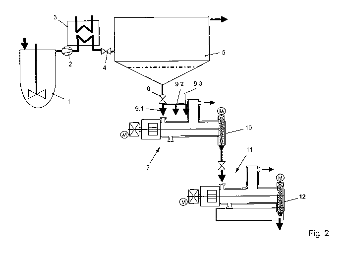
The invention provides for replacing the low-pressure separator 7 according to
Fig. 2 with a
kneader mixer 8. A corresponding kneader mixer is disclosed, for example, in
DE 591 06
245.3, DE 592 03 529.8/DE 596 08 462.5, DE 596 00 991.7, DE 500 12 557.0, DE
101 20
391.8, DE 101 50 900.6, DE 101 60 535.8 and DE 195 33 693.3. Said kneader
mixer can
have one or two shafts, can be parallel- or counter-rotating or being operated
at different
speeds.
The polymer-rich phase is supplied to the kneader mixer 8 at different feed
locations 5,
which are indicated by reference numerals 9.1, 9.2 and 9.3. These feed
locations are
distributed across the length of a single or a plurality of stirrer and/or
kneader shafts. Said
stirrer and/or kneader shafts are not shown in further detail; however, they
are arranged
horizontally or slanted, and actively route the polymer composition to a
discharge 10 such
that the treatment of higher viscosities is possible.
CA 02804072 2012-12-28
From the discharge 10, the product reaches a finisher 11, which can also be a
horizontally
disposed kneader mixer. Inside the finisher 11, the feed temperature after the
pressure
jump is adjusted such that the polymer melt is maintained above the
solidification range.
Furthermore, the invention provides for a liquid stripping agent to be added
in the finisher,
specifically at a single feed location or at a plurality of feed locations
such that, at an
adjusted pressure in the vessel space, the stripping agent evaporates, whereby
correspondingly the dosed quantity of the stripping agent is used to adjust
the temperature
of the polymer composition. By a lowering the partial pressure and improvement
of the
material exchange, it is possible to significantly reduce any achievable
content of undesired
volatile substances.
The polymer composition then reaches a further processing station via a
further discharge
12, presently not shown.
6
CA 02804072 2012-12-28
List of reference numerals
1 Stirred tank 34 67
2 Pump 35 68
3 Heat exchanger 36 69
4 Valve 37 70
High-pressure separator 38 71
6 Valve 39 72
7 Low-pressure separator 40 73
8 Kneader mixer 41 74
9 Feed location 42 75
Discharge 43 76
11 Finisher 44 77
12 Discharge 45 78
13 46 79
14 47
48
16 49
17 50
18 51
19 52
53
21 54
22 55
23 56
24 57
58
26 59
27 60
28 61
29 62
63
31 64
32 65
33 66
7