Note: Descriptions are shown in the official language in which they were submitted.
WO 2012/016692 CA 02804819 2013-01-09 PCT/EP2011/003893
BUMPER ASSEMBLY
FIELD OF THE INVENTION
[1] The instant invention relates generally to bumper assemblies for use in
vehicles,
and more particularly to a bumper crash management system including a
component that
is formed by the tailored tempering process.
BACKGROUND OF THE INVENTION
[2] Automobiles are equipped with bumpers, which are attached to either end
thereof to absorb impact in a collision and limit as far as possible any
damage to parts of
the vehicle. In order to minimize damage to vehicles during low speed impacts,
such as
for instance less than about 15-16 km/h, car manufacturers provide
"sacrificial elements"
known as crash boxes, which in the event of impact cushions most of the impact
energy,
being deformed but preventing deformation of the vehicle chassis. In fact, any
deformation of the vehicle chassis results in high repair costs, leading to
unacceptably
high insurance premiums, etc.
[3] Typically, a bumper assembly with a sacrificial element comprises a pair
of
crash boxes, a cross member, a cushioning element such as foam or the like,
and a
bumper shield. In a prior art bumper assembly, the two crash boxes are fixed
to the ends
of two respective longitudinal members of the vehicle chassis via two
respective plates.
The cross member is joined to the opposite side of the crash boxes and extends
continuously from one crash box to the other. The cushioning element made of
foam or
the like, typically, is constrained to the outside of the cross member. A
bumper shield,
having primarily aesthetic and aerodynamic functions, covers the bumper
assembly.
[4] Conventionally, both the crash boxes and the cross member are made of
metallic materials, such as for instance steel or aluminum. The prior art
solution, with
metal crash boxes, cross members and plates for fixing the crash boxes to the
vehicle, are
considered to be somewhat awkward to assemble, heavy, costly and not easily
adaptable
to new vehicle models.
1
WO 2012/016692 CA 02804819 2013-01-09PCT/EP2011/003893
[5] Accordingly, it would be advantageous to provide a crash management
system
that overcomes at least some of the above-mentioned limitations.
SUMMARY OF EMBODIMENTS OF THE INVENTION
[6] In accordance with an aspect of the invention there is provided a method
of
making a beam-box crash management system, comprising: forming a first shell
from a
first sheet metal blank by a hot forming process, the first shell having a
high tensile
strength beam portion and integrally formed therewith a first low yield
strength crash box
portion proximate a first end of the beam portion and a second low yield
strength crash
box portion proximate a second end of the beam portion, the first shell having
an open
face extending continuously along the beam portion and each of the first and
second
crash box portions; forming a closing element from a second sheet metal blank;
and,
fixedly securing the closing element adjacent to the open face of the first
shell.
[7] In accordance with an aspect of the invention there is provided amethod
of
making a beam-box crash management system, comprising: heating a first sheet
metal
blank to at least an austenitizing temperature of the metal; hot forming the
austenitic
blank in a pair of cooled tools to form a first one piece beam-box component
having a
generally three-sided channel structure with one open side; during the hot
forming
process, cooling a beam portion of the formed component at a first rate that
is sufficiently
rapid to harden the beam portion into an essentially martensitic structure
with a tensile
strength of between about 1300 N/mm2 and about 1600 N/mm2, and cooling crash
box
portions of the formed component at a second rate that is slower than the
first rate, such
that the crash box portions achieve a yield strength of between approximately
200 N/mm2
and 450 N/mm2; forming a closing element from a second sheet metal blank; and,
fixedly
securing the closing element along the open side of the first one piece beam-
box
component.
[8] In accordance with an aspect of the invention there is provided a beam-
box
crash management system, comprising: a first one piece shell having a high
tensile
strength beam portion and integrally formed therewith a first low yield
strength crash box
2
WO 2012/016692 CA 02804819 2013-01-09 PCT/EP2011/003893
portion proximate a first end of the beam portion and a second low yield
strength crash
box portion proximate a second end of the beam portion, the first one piece
shell having
an open face extending continuously along the beam portion and each of the
first and
second crash box portions; and, a closing element fixedly secured adjacent to
the open
face of the first one piece shell.
[009] In accordance with an aspect of the invention there is provided abeam-
box crash
management system, comprising: a first beam-box shell, fabricated from a first
sheet
metal blank, having a high tensile strength beam portion and integrally formed
therewith
a first low yield strength crash box portion proximate a first end of the beam
portion and
a second low yield crash box portion proximate a second end of the beam
portion, the
first end being opposite the second end, and the first beam-box shell having
one open side
defining a first rim; a second beam-box shell, fabricated from a second sheet
metal blank,
having a high tensile strength beam portion and integrally formed therewith a
first low
yield strength crash box structure proximate a first end of the beam portion
and a second
low strength crash box structure proximate the second end of the beam portion,
the first
end being opposite the second end, and the second beam-box shell having one
open side
defining a second rim; wherein the first beam-box shell is fixedly secured to
the second
beam-box shell such that the first rim abuts the second rim, and such that the
beam
portion of the first beam-box shell is aligned with the beam portion of the
second beam-
box shell and the first and second crash box structures of the first beam-box
shell are
aligned with a respective one of the first and second crash box structures of
the second
beam-box shell.
BRIEF DESCRIPTION OF THE DRAWINGS
[0010] Exemplary embodiments of the invention will now be described in
conjunction
with the following drawings, in which:
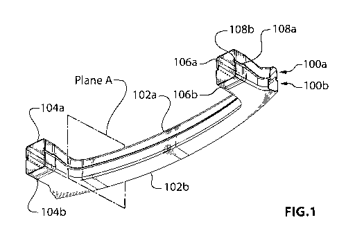
[0011] FIG. 1 is a rear perspective view of a crash management system
according to a
first embodiment of the instant invention;
[0012] FIG. 2 is an enlarged cross-sectional view taken in the Plane A of FIG.
1;
3
WO 2012/016692 CA 02804819 2013-01-09PCT/EP2011/003893
[0013] FIG. 3 is a front perspective view of a crash management system
according to a
second embodiment of the instant invention;
[0014] FIG. 4a is a rear perspective view of the crash management system of
FIG. 3;
[0015] FIG. 4b is an enlarged detail view of a portion of FIG. 4a lying within
one of the
dashed-line circles;
[0016] FIG. 4c is an enlarged detail view of a portion of FIG. 4a lying within
the other
one of the dashed-line circles;
[0017] FIG. 5 is a simplified flow diagram of a method according to an
embodiment of
the instant invention; and,
[0018] FIG. 6 is a simplified flow diagram of a method according to an
embodiment of
the instant invention.
DETAILED DESCRIPTION OF EMBODIMENTS OF THE INVENTION
[0019] The following description is presented to enable a person skilled in
the art to
make and use the invention, and is provided in the context of a particular
application and
its requirements. Various modifications to the disclosed embodiments will be
readily
apparent to those skilled in the art, and the general principles defined
herein may be
applied to other embodiments and applications without departing from the scope
of the
invention. Thus, the present invention is not intended to be limited to the
embodiments
disclosed, but is to be accorded the widest scope consistent with the
principles and
features disclosed herein.
[0020] Referring to FIG. 1, shown is a rear perspective view of a crash
management
system according to a first embodiment of the instant invention. The crash
management
system comprises a first shell 100a and a second shell 100b. The first shell
100a is
formed from a first sheet metal blank and the second shell 100b is formed
separately
from a second sheet metal blank. By way of a specific and non-limiting
example, the
first and second sheet metal blanks each comprise 22MnB5 boron steel. More
4
WO 2012/016692 CA 02804819 2013-01-09PCT/EP2011/003893
particularly, the first shell 100a and the second shell 100b are formed using
a tailored
tempering hot forming process, as is described in greater detail in the
following sections.
[0021] The first shell 100a comprises a high tensile strength beam portion
102a.
Integrally formed with the beam portion 102a is a first low yield strength
crash box
portion 104a proximate a first end of the beam portion and a second low yield
strength
crash box portion 106a proximate a second end of the beam portion, the second
end being
opposite the first end. Similarly, the second shell 100b comprises a high
tensile strength
beam portion 102b. Integrally formed with the beam portion 102b is a first low
yield
strength crash box portion 104b proximate a first end of the beam portion and
a second
low yield strength crash box portion 106b proximate a second end of the beam
portion,
the second end being opposite the first end.
[0022] A typical value of the tensile strength of the beam portions 102a and
102b is
between about 1300 N/mm2 and about 1600 N/mm2. A typical value of the yield
strength
of the first and second crash box portions 104a/b and 106a/b, respectively, is
between
about 200 N/mm2 and about 450 N/mm2. The yield strength of the crash box
portions is
adjustable during the hot forming process, to achieve desired values depending
upon
performance requirements. Due to the nature of the hot forming process that is
used to
form the first shell 100a and the second shell 100b, a transition zone exists
between the
high tensile strength material of the beam portion 102a/b and the low yield
strength
material of the first and second crash box portions 104a/b and 106a/b.
[0023] Referring also to FIG. 2, shown is an enlarged cross-sectional view
taken in the
Plane A of FIG. I. The first shell 100a is a unitary component having a
generally three-
sided channel structure with one open side. A top surface 200a of the first
shell 100a
extends into two opposite sidewalls 202a and 204b. The edges of the two
opposite
sidewalls along the open side of the first shell define a first rim 108a.
Similarly, the
second shell 100b is also a unitary component having a generally three-sided
channel
structure with one open side. A bottom surface 200b of the second shell 100b
extends
into two opposite sidewalls 202b and 204b. The edges of the two opposite
sidewalls
202b and 204b along the open side of the first shell define a second rim 108b.
The
5
WO 2012/016692 CA 02804819 2013-01-09 PCT/EP2011/003893
second rim 108b is shaped to nest inside the first rim 108a when the first
shell 100a is
fixedly secured to the second shell 100b. The generally three-sided channel
structures
extend the length of the beam portions 102a and 102b, and through the first
and second
crash box portions 104a/b and 106a/b, respectively. Of course, it is to be
understood that
the terms "top" and "bottom" as used herein are defined in the context of FIG.
2, and that
they are not intended to imply any required orientation of the crash
management system
when in an installed condition.
[0024] Optionally, the first and second crash box portions 104a/b and 106a/b
are
formed with "beads" (not shown) to optimize folding behavior during an impact.
[0025] A method of making the crash management system of FIG. 1 includes
heating
the first blank of flat sheet steel in a furnace to austenitic state, moving
the first blank into
a cooled pair of shaping tools, and then pressing the hot first blank into the
shape of the
first shell 100a. The shaped first shell 100a is maintained in the tools until
the beam
portion 102a has hardened into an essentially martensitic structure with a
tensile strength
of between about 1300 N/mm2 and about 1600 N/mm2. During the time the first
shell
100a is maintained in the tools, a portion of each tool adjacent the first and
second crash
box portions 104a and 106a, respectively, is maintained at such a temperature
that the
first and second crash box portions 104a and 106a, respectively, are prevented
from rapid
cooling and will reach only a yield strength of between about 200 N/mm2 and
about 450
N/mm2. By way of a specific and non-limiting example, heat is added (e.g.,
using
cartridge heaters) to the portion of each tool adjacent the first and second
crash box
portions 104a and 106a, respectively, and/or the portion of each tool adjacent
the first and
second crash box portions 104a and 106a, respectively, is insulated such that
the rate of
heat loss from said crash box portions is reduced relative to the rate of heat
loss of non-
insulated portions.
[0026] Similarly, the second blank of flat sheet steel is heated in a furnace
to austenitic
state, is moved into a cooled pair of shaping tools, and is pressed while
still hot first into
the shape of the second shell 100b. The shaped second shell 100b is maintained
in the
tools until the beam portion 102b has hardened into an essentially martensitic
structure
6
WO 2012/016692 CA 02804819 2013-01-09PCT/EP2011/003893
with a tensile strength of between about 1300 N/mm2 and about 1600 N/mm2.
During the
time the second shell 100b is maintained in the tools, a portion of each tool
adjacent the
first and second crash box portions 104b and 106b, respectively, is maintained
at such a
temperature that the first and second crash box portions 104b and 106b,
respectively, are
prevented from rapid cooling and will reach only a yield strength of between
about 200
N/mm2 and about 450 N/mm2. By way of a specific and non-limiting example, heat
is
added (e.g., using cartridge heaters) to the portion of each tool adjacent the
first and
second crash box portions 104b and 106b, respectively, and/or the portion of
each tool
adjacent the first and second crash box portions 104b and 106b, respectively,
is insulated
such that the rate of heat loss from said crash box portions is reduced
relative to the rate
of heat loss of non-insulated portions.
[0027] The separately formed first shell 100a and second shell 100b are
aligned one
with the other and then fixedly secured together. Some non-limiting techniques
for
fixedly securing the first shell 100a to the second shell 100b include:
thermal joining
(such as for instance spot welding, metal inert gas (MIG) welding, laser
welding, etc.);
adhesive bonding; and, mechanical coupling (such as for instance clinching or
riveting).
According to the first embodiment, the second shell 100b is a closing element
that is
fixedly secured to the first shell 100a.
[0028] Referring now to FIG. 3, shown is a front perspective view of a crash
management system according to a second embodiment of the instant invention.
The
crash management system comprises a one-piece shell 300 that is formed from a
first
sheet metal blank, and a not illustrated closing element. By way of a specific
and non-
limiting example, the first sheet metal blanks comprises 22MnB5 boron steel.
More
particularly, the one-piece shell 300 is formed using a tailored tempering hot
forming
process, as is described in greater detail in the following sections.
[0029] The one-piece shell 300 comprises a high tensile strength beam portion
302.
Integrally formed with the beam portion 302 is a first low yield strength
crash box
portion 304 proximate a first end of the beam portion and a second low yield
strength
crash box portion 306 proximate a second end of the beam portion, the second
end being
7
WO 2012/016692 CA 02804819 2013-01-09 PCT/EP2011/003893
opposite the first end. A typical value of the tensile strength of the beam
portion 302 is
between about 13001=1/mm2 and about 16001=I/mm2. A typical value of the yield
strength
of the first and second crash box portions 304 and 306, respectively, is
between about
200N/mm2 and about 4501=1/mm2. The yield strength of the crash box portions is
adjustable during the hot forming process, to achieve desired values depending
upon
performance requirements. Due to the nature of the hot forming process that is
used to
form the one-piece shell 300, a transition zone exists between the high
tensile strength
material of the beam portion 300 and the low yield strength material of the
first and
second crash box portions 304 and 306.
[0030] Referring now to FIG. 4a, shown is a rear perspective view of the crash
management system of FIG. 3. Also shown in FIG. 4a is the closing element 400.
In
particular, the closing element 400 is a cold stamped part that has mid-range
strength.
More particularly, the properties of the closing element are approximately the
same as the
properties of the crash box portions 304 and 306.
[0031] Referring also to FIG. 4b, shown is an enlarged detail view of the
portion of
FIG. 4a lying within the dashed-line circle. The one-piece shell 300 is a
unitary
component having a generally three-sided channel structure with one open side.
A top
surface 402 of the one-piece shell 300 extends into two opposite sidewalls 404
and 406.
The edges of the two opposite sidewalls along the open side of the first shell
define a rim
408. The generally three-sided channel structure extends the length of the
beam portion
302, and through the first and second crash box portions 304 and 306. Also
shown in
FIG. 4b, the closing element 400 has a peripheral flange 410 for use in
fixedly securing
the closing element 400 to the rim 408 of the one-piece shell 300. Of course,
it is to be
understood that the term "top" as used herein is defined in the context of
FIG. 4, and that
it is not intended to imply any required orientation of the crash management
system when
in an installed condition.
[0032] Referring also to FIG. 4c, shown is an enlarged detail view of a
portion of FIG.
4a lying within the other dashed-line circle. FIG. 4c shows that the corner
between the
8
WO 2012/016692 CA 02804819 2013-01-09 PCT/EP2011/003893
crash boxes and the beam portion may optionally be notched out (notch 412),
for
formability reasons.
[0033] Optionally, the first and second crash box portions 304 and 306 are
formed with
"beads" (not shown) to optimize folding behavior during an impact.
[0034] A method of making the crash management system of FIG. 3 includes
heating
the first blank of flat sheet steel in a furnace to austenitic state, moving
the first blank into
a cooled pair of shaping tools, and then pressing the hot first blank into the
shape of the
one-piece shell 300. The shaped one-piece shell 300 is maintained in the tools
until the
beam portion 302 has hardened into an essentially martensitic structure with a
tensile
strength of between about 1300 N/mm2 and about 1600 N/mm2. During the time the
one-
piece shell 300 is maintained in the tools, a portion of each tool adjacent
the first and
second crash box portions 304 and 306, respectively, is maintained at such a
temperature
that the first and second crash box portions 304 and 306, respectively, are
prevented from
rapid cooling and will reach only a yield strength of between about 200 N/mm2
and about
450 N/mm2. By way of a specific and non-limiting example, heat is added (e.g.,
using
cartridge heaters) to the portion of each tool adjacent the first and second
crash box
portions 304 and 306, respectively, and/or the portion of each tool adjacent
the first and
second crash box portions 304 and 306, respectively, is insulated such that
the rate of
heat loss from said crash box portions is reduced relative to the rate of heat
loss of non-
insulated portions.
[0035] Separately, the closing element 400 is cold stamped from a suitable,
mid-
strength steel stock. The flange 410 of the closing element 400 is then
aligned with the
rim 408 along the open side of the one-piece shell 300, and the closing
element 400 is
fixedly secured to the one-piece shell 300. Some non-limiting techniques for
fixedly
securing the one-piece shell 300 to the closing element include: thermal
joining (such as
for instance spot welding, metal inert gas (MIG) welding, laser welding,
etc.); adhesive
bonding; and, mechanical coupling (such as for instance clinching or
riveting).
[0036] Referring to FIG. 5, shown is a simplified flow diagram of a method
according
to an embodiment of the instant invention. At 500 a first shell is formed from
a first
9
WO 2012/016692 CA 02804819 2013-01-09PCT/EP2011/003893
sheet metal blank by a hot forming process, the first shell having a high
tensile strength
beam portion and integrally formed therewith a first low yield strength crash
box portion
proximate a first end of the beam portion and a second low yield strength
crash box
portion proximate a second end of the beam portion, the first shell having an
open face
extending continuously along the beam portion and each of the first and second
crash box
portions. At 502 a closing element is formed from a second sheet metal blank.
At 504
the closing element is fixedly secured adjacent to the open face of the first
shell.
[0037] Referring to FIG. 6, shown is a simplified flow diagram of a method
according
to an embodiment of the instant invention. At 600 a first sheet metal blank is
heated to at
least an austenitizing temperature of the metal. At 602 the austenitic blank
is hot formed
in a pair of cooled tools to form a first one-piece beam-box component having
a generally
three-sided channel structure with one open side. At 604, during the hot
forming process,
a beam portion of the formed component is cooled at a first rate that is
sufficiently rapid
to harden the beam portion into an essentially martensitic structure with a
tensile strength
of between about 1300 N/mm2 and about 1600 N/mm2, and crash box portions of
the
formed component are cooled at a second rate that is slower than the first
rate, such that
the crash box portions achieve a yield strength of between approximately 200
N/mm2 and
450 N/mm2. At 606 a closing element is formed from a second sheet metal blank.
At
608 the closing element is fixedly secured along the open side of the first
one-piece
beam-box component.
[0038] The descriptions of the crash management systems according to the
various
embodiments of the instant invention have omitted any mention of routine
mounting
structures, such as through-holes etc., which are used for securing said crash
management
system to the longitudinal members of a vehicle chassis, or for securing a
cushioning
element or bumper cover to said crash management system. Nevertheless, a
person
having ordinary skill in the art will understand the requirements for such
mounting
structures, based on the various views that are presented in the appended
drawings.
[0039] In addition, the method of imparting tailored strength properties to
the final
components has been described only in terms of one specific and non-limiting
method, in
10
WO 2012/016692 CA 02804819 2013-01-09PCT/EP2011/003893
which a blank is heated uniformly to austenitic state and selected portions
are cooled at a
rate during forming, which results in lower strength in said selected portions
relative to
other portions. Optionally, only some portions of the blank are heated
initially to
austenitic state, and selected portions are either shielded from heating or
kept in a lower
temperature environment (e.g., external to a furnace or within a cooler
furnace portion)
such that the austenitizing temperature of the material in said selected
portions is not
exceeded. Further optionally, the blank is formed and selected portions are
heated
subsequently (e.g., by inductive heating) to austenitic state and then rapidly
cooled to
achieve high strength in said selected portions. Still further optionally, the
entire
component is formed with rapid cooling, and subsequently selected portions are
heated to
a temperature that is sufficiently high to induce a phase change in said
selected portions,
followed by controlled cooling at a rate that results in a softening of the
material in said
selected portions relative to the non-heated portions.
[0040] Depending on performance requirements, yield strengths of the first and
second
crash box portions may be outside of the range of approximately 200 N/mm2 and
450
N/mm2. This range currently is understood to provide acceptable performance,
but
should not be regarded as a strict requirement for achieving acceptable
performance of
the beam-box crash management component.
[0041] Numerous other embodiments may be envisaged without departing from the
scope of the instant invention.
11