Note: Descriptions are shown in the official language in which they were submitted.
CA 02804952 2013-01-09
WO 2012/021501 PCT/US2011/047057
1
DESCRIPTION
DEVICE AND METHOD FOR ABSCESS IRRIGATION
CROSS-REFERENCE TO A RELATED APPLICATION
This application claims the benefit of U.S. provisional application Serial No.
61/371,981, filed August 9, 2010, which is incorporated herein by reference in
its entirety.
BACKGROUND OF THE INVENTION
An abscess is a localized collection of pus within the body. Abscesses are
typically
caused when the body tries to fight an infection within the tissues of the
body, sending white
blood cells to fight further infection. The blood cells collect around the
initial site of
infection, accumulating to form pus. As the white blood cells die and the
infection increases,
the surrounding healthy tissues form an "abscess wall", or capsule, around the
pus in an
attempt to prevent it from infecting neighboring structures. However, this
encapsulation of
the pus and the abscess wall tend to prevent further immune cells from
attacking bacteria in
the pus, or from reaching the causative organism or foreign object.
Abscesses can develop in many parts of the body, but they often involve the
skin
surface. Skin abscesses are often referred to as boils. Unlike other
infections, antibiotics
alone may not cure a large abscess. Usually, large abscesses must open and
drain to improve.
Although sometimes an abscess will open and drain spontaneously, it often
needs to be
opened and drained (incision and drainage) by a health care provider.
The standard treatment procedure is for a doctor to use a local anesthetic to
numb the
affected area. A sedative may even be needed if the abscess is large. Using a
scalpel, the
abscess is lanced and allowed to drain, removing the pus and any other debris
from the area.
To minimize scarring, it can be preferable to make the incision only as large
as necessary to
promote drainage. Antibiotics and hot compresses are usually prescribed. Large
abscesses
can result in an abscess pocket remaining under the skin after all the pus is
drained, which
usually necessitates repeated fluid irrigation during the healing process to
wash away
accumulated debris, sloughed tissue, or recurring pus formation. Ideally, an
abscess is
allowed to heal from the inside out. Thus, once drained, the wound is kept
open to facilitate
periodic irrigation, continued drainage and promote proper healing. Large
abscesses may be
WO 2012/021501 CA 02804952 2013-01-09 PCT/US2011/047057
2
packed with sterile gauze, although there is some evidence to show that this
can impede the
healing process. (O'Malley, G.F. et al., (2009) "Routine Packing of Simple
Cutaneous
Abscesses is Painful and Probably Unnecessary," Academic Emergency Medicine,
16(5):
470-473.)
If the area does not drain sufficiently and/or irrigation is not performed
adequately,
the abscess will refoini. This often happens if the wound opening or abscess
incision closes
too soon, or if the abscess is too deep for all of the pus to drain or be
irrigated from the
incision. Applying pressure to the area to force the pus to drain is not
recommended since
that can actually force the pus deeper into the tissues, causing further
damage.
Irrigation is the most common and safest procedure for cleansing and debriding
open
contaminated wounds. Irrigation involves the application of sterile solutions
or fluids to
wounds to remove loose devitalized tissue, bacterial inoculum, blood clots,
loose debris, and
foreign bodies proximate to and within the depths of the wound. The two
critical components
of any effective wound irrigation method and/or device are: (1) the
application of an adequate
volume of sterile irrigation solution to the wound, and (2) the use of
sufficient pressure
applied in an effective dispersal pattern in the delivery of the solution to
effectively remove
contaminants. It is not uncommon for wounds, to require a liter or more of
irrigation
solution. (Mulliken, John B. (1984) "Management of Wounds," in Emergency
Medicine,
May ed., John Wiley & Sons, pp. 283-286.) It has also been demonstrated that
stream
pressure of a minimum of 4 pounds per square inch (psi) (and, preferably, 7
psi) is required to
effectively flush or remove contaminants from a wound. See, for example,
Rodeheaver, G.T.
Wound Cleaning, Wound Irrigation, Wound Disinfection, In: Krasner, D., Kane,
D. Chronic
Wound Care. 2nd ed. Wayne, P.A.: Health Management Publications; 1997, pp 97-
108; and
Bergstrom, N., Bennett, M.A., Carlson, C.E. et al. Treatment of Pressure
Ulcers. Clinical
Guideline No. 15. AHCPR Publication No. 95-0652. Rockville, MD. Department of
Health
and Human Services. Public Health Services. Agency of Health Care Policy and
Research;
December 1994.)
Irrigation pressure in excess of desired limits (e.g., 25 psi or greater) may
actually
drive bacteria and particulate matter deeper into the wound and thereby defeat
the purpose of
the irrigation process. High-pressure irrigation may also cause damage to
healthy tissue and
impede the tissue's defenses and retard healing. Thus, effective wound
irrigation requires the
WO 2012/021501 CA 02804952 2013-01-09PCT/US2011/047057
use and application of adequate volumes of irrigation solution delivered to
the wound in an
effective dispersal pattern at appropriate pressures.
Unfortunately, most irrigation devices and methods are effective only on
relatively
shallow wounds or larger open wounds, such as burns or large open cuts. Deeper
wounds,
particularly those with smaller openings, such as abscesses or puncture
wounds, would obtain
only minimal benefit from a surface irrigation procedure. Devices currently
used to cleanse
deeper wounds, such as various types of syringe models, often do not have
sufficient
pressure, or fluid dispersion to actually debride tissues and/or cannot
deliver a sufficient
amount of solution to thoroughly flush out an abscess or similar wound.
More recently, an advantageous wound irrigation system has been developed
whereby
a dispersed stream of irrigation fluid is easily and effectively applied to
wounds. This system
is described at, for example, U.S. Patent Nos. 5,830,197 and 6,468,253 and
International
Patent Applications WO 00/15279 and WO 02/007799. A specific embodiment of
this
system is also disclosed in U.S. Design Patents D588,692 and D556,595.
Although the use of the dispersed stream is highly advantageous for cleansing
wounds, it has been determined that the shape and size of the nozzles
delivering the irrigation
fluid can be improved for use in irrigating puncture wounds, abscesses, and
similar deep
tissue wounds.
BRIEF SUMMARY OF THE INVENTION
The subject invention successfully addresses the above described disadvantages
associated with the previously known abscess irrigation devices and methods,
and provides
certain attributes and advantages, which have not been realized by these known
devices.
In particular, the subject invention provides novel, inexpensive, and highly
effective
methods and devices for convenient and effective irrigation of abscesses and
other deep
tissue wounds. In one embodiment, the subject invention provides a discharge
apparatus (LT
SplatterGuardTM) for a reservoir housing containing irrigation solution,
wherein the discharge
apparatus has one or more specifically designed nozzles for penetration into
an abscess
capsule or other wound, and through which a sufficient volume of the
irrigation solution can
pass at an appropriate pressure for effective cleansing and debriding.
Surrounding the nozzle
can be a backsplash shield that reduces or eliminates backsplash and/or
aerosol hazards to
healthcare providers when expressing irrigation solution from the reservoir.
CA 02804952 2013-01-09
WO 2012/021501 PCT/US2011/047057
4
In particular embodiments, the device has a slender, elongated nozzle with a
plurality
of outlet ports. In a further embodiment, the nozzle and plurality of outlet
ports are
specifically designed to reduce loss of pressure as the irrigation fluid
leaves the reservoir
housing. There are three elements of the design that can be particularly
important ¨ the
shape of the nozzle, the length of the nozzle, and the configuration of the
plurality of outlet
ports. In a specific embodiment, the nozzle is generally slender, elongated,
and comprises
several passageways or outlet ports. In a further embodiment, the nozzle is
surrounding by a
backsplash shield.
In a further particular embodiment, the reservoir housing, upon which a
discharge
apparatus can be either permanently or detachably affixed, is compressible
(e.g., plastic
bottles in which saline or other solutions are presently available). The
operator (i.e., medical
or health care professional or other person) using the subject device and
providing wound
irrigation therapy can insert the end of the nozzle into a wound opening, such
as an abscess
incision, or puncture opening and easily compress the reservoir housing to
force the irrigation
solution through the outlet ports of the discharge apparatus under sufficient
pressure to
dislodge dirt, debris, devitalized tissue, or other particles, including
microorganisms, e.g.,
pathogenic bacteria. Continued compression fills and flushes the wound or
abscess cavity,
removing the debris and leaving a clean and debrided cavity less susceptible
to infection and
more amenable to the normal healing process.
Specifically exemplified herein is the use of a single, elongated nozzle, with
multiple
outlet ports to achieve optimum dispersal, pressure, and volume of the stream
of irrigation
solution.
In a further embodiment, the subject invention provides a laceration tray that
has
items conveniently provided for treating wounds.
In yet another embodiment, the subject invention provides a drain pan for
collection
of fluids.
In still another embodiment, the subject invention provides a sterile product
for use in
an operating room environment.
In another embodiment, the subject invention provides a pressurized irrigation
assembly comprising: irrigation solution; a reservoir housing that contains
the irrigation
solution; a discharge apparatus having a specifically designed nozzle with
multiple outlet
ports through which a sufficient volume of the irrigation solution can pass at
an appropriate
WO 2012/021501 CA 02804952 2013-01-09PCT/US2011/047057
5
pressure; and a means for creating pressure for the generation of dispersed
streams through
the outlet ports in the nozzle to cleanse and flush abscesses or other deep
tissue wounds.
The devices and methods disclosed herein provide an easy to use, economical
wound
irrigation system that is capable of delivering adequate volumes of irrigation
solution
(without refilling the reservoir) in a dispersed stream under sufficient
pressure to effectively
cleanse and flush the wound, thereby reducing the presence of infection and
the possibility of
recurrence of the abscess.
An operator, without assistance, can easily penetrate a wound opening with the
nozzle
and direct and control the application of irrigation solution into the wound
or abscess with
one hand. This can leave the other hand free for other activities, such as
separation of the
wound opening, compression of the wound site to expel the solution and other
material
carried therewith, and to further facilitate irrigation of the wound interior
and/or exterior.
BRIEF SUMMARY OF THE FIGURES
In order that a more precise understanding of the above recited invention can
be
obtained, a more particular description of the invention, briefly described
above, will be
rendered by reference to specific embodiments thereof that are illustrated in
the appended
drawings. It should be understood that the drawings presented herein may not
be drawn to
scale and that any reference to dimensions in the drawings or the following
description are
specific to the embodiments disclosed. Any variations of these dimensions that
will allow the
subject invention to function for its intended purpose are considered to be
within the scope of
the subject invention. Thus, understanding that these drawings depict only
typical
embodiments of the invention and are not therefore to be considered as
limiting in scope, the
invention will be described and explained with additional specificity and
detail through the
use of the accompanying drawings in which:
Figure 1 shows a front elevation view of one embodiment of an abscess
irrigation
device of the subject invention that includes a compressible reservoir
housing, and a
discharge apparatus having a nozzle for directing a pressurized stream of
irrigation solution
into an abscess.
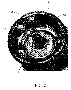
Figure 2 shows an enlarged perspective view of an embodiment of the discharge
apparatus of the abscess irritation device of the subject invention.
CA 02804952 2013-01-09
WO 2012/021501 PCT/US2011/047057
6
Figure 3 shows a front elevation view of an embodiment of the discharge
apparatus
of subject invention.
Figure 4 shows a cross-sectional view of the embodiment in Figure 3.
Figure 5 shows an enlarged right-side perspective view of an embodiment of the
nozzle, particularly the outlet ports, and gutters of a specific embodiment of
the subject
invention.
Figure 6 shows the enlarged perspective view of Figure 5A with arrows
indicating
the direction of fluid flow from the nozzle outlet ports.
Figure 7 shows an enlarged top plan view of one embodiment of the nozzle and
outlet
ports therein of the subject invention.
Figure 8 shows an enlarged sectional side view of the nozzle of Figure 7.
Figure 9 shows a top plan view of the proximal end of an alternative
embodiment of a
nozzle having a straight-cut gutter configuration. Note that the gutters form
straight edges
around the proximal end of the nozzle.
Figure 10 shows a side cross-sectional view of an embodiment of the invention,
wherein the outlet ports have a 60 angle of inclination.
Figure 11 is a photograph illustrating a procedure for anesthetizing an
abscessed
wound.
Figure 12 is a photograph illustrating a procedure for lacerating an abscessed
wound
to provide access to the abscess pocket.
Figure 13 is a photograph illustrating a procedure for disrupting loculations
that may
be present within the abscessed wound.
Figure 14 is a photograph illustrating a procedure for manually expressing
exudates
from an abscess pocket.
Figure 15 is a photograph illustrating use of one embodiment of the subject
invention,
wherein the nozzle of the discharge apparatus is inserted into the abscessed
wound and fluid
from the reservoir housing is expressed through the nozzle and out of the
outlet ports into the
abscess pocket.
Figure 16 is a photograph illustrating use of one embodiment of the subject
invention
wherein one hand is used to control the discharge apparatus and the other hand
is used to
manipulate the abscess pocket opening.
CA 02804952 2013-01-09
WO 2012/021501 PCT/US2011/047057
7
Figure 17 illustrates an alternative embodiment wherein the discharge
apparatus
comprises an elongated nozzle with four outlet ports, but does not include a
backsplash
shield.
Figure 18 is a side plan view of an alternative embodiment of the discharge
apparatus, including specific dimensions.
Figure 19 is an enlarged view of the alternative embodiment shown in Figure
18,
specifically illustrating the nozzle end and details of an alternative
embodiment of the outlet
ports. Specifically illustrated in this embodiment are outlet ports having
straight, parallel
sides that direct fluid in a generally straight line directly from the nozzle
tip.
Figure 20 is an enlarged view of the edge of the alternative embodiment of a
discharge apparatus. This embodiment includes a plurality of raised ribs
around the outside
of the discharge apparatus to facilitate gripping or holding of the discharge
apparatus,
particularly if it is being transferred from one reservoir housing to another.
In a further
embodiment, as shown, the ribs are tapered at their proximal end, so that they
blend with or
are flush with the surface of the discharge apparatus. In a further
embodiment, the distal end
of the ribs is rounded and smooth and is contiguous with the distal end edge
of the discharge
apparatus.
DETAILED DESCRIPTION OF THE INVENTION
The subject invention provides novel, convenient, inexpensive, and effective
abscess
irrigation devices that can include a reservoir housing and a discharge
apparatus having a
single nozzle with one or more outlet ports for irrigation of an abscess. The
subject invention
also provides methods of use for the device.
The materials and methods of the subject invention make it possible to
conveniently
and easily direct one or more streams of irrigation fluid into an abscess with
the stream(s)
having an appropriate volume, pressure, and dispersal pattern. Under optimal
circumstances,
the abscess irrigation devices and methods of the subject invention are
utilized by trained
medical technicians; however, because of the simplicity and convenience of the
devices of
the subject invention, they can be used to greatly enhance the effectiveness
of abscess
irrigation regardless of the training level of the operator performing the
irrigation.
The subject invention is particularly useful in the field of wound irrigation,
in
particular abscess irrigation. However, a person with skill in the art will be
able to recognize
CA 02804952 2013-01-09
WO 2012/021501 PCT/US2011/047057
8
numerous other uses that would be applicable to the devices and methods of the
subject
invention. While the subject application describes a use for irrigation of
abscesses and/or
abscess pockets, other uses, and resulting modifications therefor, that are
apparent to a person
with skill in the art having benefit of the subject disclosure are
contemplated to be within the
scope of the present invention.
The present invention is more particularly described in the following examples
that
are intended to be illustrative only since numerous modifications and
variations therein will
be apparent to those skilled in the art. As used in the specification and in
the claims, the
singular for "a," "an" and "the" include plural referents unless the context
clearly dictates
otherwise.
Finally, the various components referred to herein are described with
reference to the
"proximal end" and/or "distal end." As used herein, the proximal end 200 is
that end of the
device that, in use, would be placed nearest to or within an abscess.
Conversely, the distal
end 300 of the device is that end that, in use, is furthest from an abscess
and from the
proximal end.
In one embodiment, the nozzle and outlet ports of the subject invention are
designed
to expel irrigation fluid(s) into an abscess pocket. In a particular
embodiment, the nozzle and
outlet ports of the current invention are specifically designed to reduce
pressure loss as the
irrigation fluid leaves the reservoir housing. The outlet ports can disperse
fluid in a variety of
directions. In one embodiment, the outlet ports disperse fluid in a single
direction, such as,
for example, straight out from the nozzle tip. In an alternative embodiment,
the outlet ports
of the nozzle are specifically designed to provide a wide dispersal pattern as
the irrigation
fluid leaves the reservoir housing. Thus, there are three elements of the
design that are
particularly important ¨ the shape of the nozzle, the length of the nozzle,
and the
configuration of the one or more outlet ports. Preferably, the nozzle is
elongated and
comprises a single shaped passageway, or bore, that leads to the one or more
outlet ports for
dispersal of the irrigation fluid.
In one embodiment, the nozzle acts similar to a jet through which irrigation
fluid is
forced, under pressure, to achieve velocities and pressures appropriate for
efficient abscess
irrigation. The nozzle and outlet ports are designed to reduce friction and
turbulence and
facilitate achieving sufficient irrigation pressures with minimal operator
effort.
CA 02804952 2013-01-09
WO 2012/021501 PCT/US2011/047057
9
With reference to the attached figures, which show certain embodiments of the
subject invention, it can be seen that embodiments of the subject invention
include a
discharge apparatus 80 for attachment to a reservoir housing , as shown, for
example, in
Figure 1. In a more particular embodiment, the discharge apparatus includes a
nozzle 98
attached to, or attachable to, the discharge apparatus and a backsplash shield
90 either
attached to or attachable to the reservoir housing 60. The nozzle 98 can
further have at least
one inlet port 102 and one or more outlet ports 104.
In one embodiment, the nozzle 98 defines a bore 99 that delivers a stream of
irrigation
fluid from the inside to the outside of the reservoir housing 60. Figures 3
and 4 illustrate one
embodiment of the subject invention. In accordance with this embodiment, the
length of the
nozzle 98 from the inlet port 102 to the outlet ports 104 is between
approximately 1.5 inches
and approximately 2.5 inches. In a more particular embodiment, the length of
the nozzle
from the inlet port 102 to the outlet ports 104 is between approximately 1.8
inches and
approximately 2.0 inches. In a specific embodiment, the nozzle extends between
approximately 1.0 inches and 1.3 inches beyond the rim 92 of the backsplash
shield 90. In a
more specific embodiment, the proximal end of the nozzle extends about 1.2
inches beyond
the rim 92 of the backsplash shield.
In an alternative embodiment, an example of which is shown in Figures 17 and
18, the
total length of the discharge apparatus and nozzle is between approximately 3
inches and 4
inches. In a more specific embodiment, the total length of the discharge
apparatus and nozzle
is approximately 4.3 inches. In a still more particular embodiment, the length
of the nozzle is
approximately 3.5 inches and the length of the discharge apparatus is
approximately 0.8
inches.
In certain embodiments of the invention, the nozzle is a "shaped" nozzle that
defines
the passageway through which the fluid travels (see Figures 4 and 8). In one
embodiment,
the passageway extends through the length of the nozzle and is defined by the
bore 99, which
narrows as it approaches the outlet ports 104. The passageway of the nozzle
can limit the
generation of turbulence in the irrigation fluid as it passes through the
nozzle(s) during
operation of the abscess irrigation device of the subject invention.
Therefore, fluid passing
through the nozzle experiences laminar flow (or at least a reduction in
turbulence) as it passes
through and exits the nozzle through the output ports. Thus, as used herein,
reference to the
"shaped" passageway refers to a nozzle with a passageway where the cross-
sectional area of
WO 2012/021501 CA 02804952 2013-01-09PCT/US2011/047057
10
the inlet port 102 is greater than the cross-sectional area of the one or more
outlet ports 104.
This shaped nozzle has been found to be particularly advantageous for
achieving desired
irrigation fluid pressures and velocities according to embodiments of the
subject invention.
In a specific embodiment, the nozzle bore 99 is defined by a funnel shape or
conical
shape where the nozzle cross-section decreases from an upstream wider end at
or near the
inlet port 102 to the downstream end at or near the outlet ports 104.
Figures 2, 3, and 4 show a specific embodiment of the elongated, shaped nozzle
of the
subject invention. In this embodiment, the nozzle extends approximately 1.2
inches above
the rim 92 of the backsplash shield 90.
As would be appreciated by a person skilled in the art having the benefit of
the current
disclosure, the nozzle of the subject invention can be formed from and/or
extend from the
material of the discharge apparatus 80. Thus, for example, if the discharge
apparatus is
formed of a plastic material, the nozzle can be formed of and extend
proximally from the
same material of the discharge apparatus, such that the bore extends through
the discharge
apparatus. Alternatively, the nozzle can be formed as a separate piece, and
even a different
material than the discharge apparatus, and can be attached to the discharge
apparatus. In this
alternative embodiment, the discharge apparatus has an opening that is
contiguous with the
bore 99, when the nozzle is attached thereto.
The embodiments disclosed herein are specifically designed to permit
irrigation of an
abscess. Thus, the elongated nozzle permits the proximal end to be placed
within close
proximity to the abscess opening. However, it can be more beneficial if the
proximal end is
inserted within the abscess opening, e.g., within the drainage incision. This
can allow the
force of the irrigation fluid to debride affected tissues and better cleanse
the interior of the
abscess pocket, to promote better healing from the inside out. To assist with
insertion of the
nozzle into an abscess opening, the nozzle can be narrow or slender in
diameter for easy
insertion and to prevent damage to surrounding tissue. In one embodiment the
nozzle is an
elongated tubular-like structure having an exterior diameter of between
approximately 0.125
inches and approximately 0.375 inches. In a more particular embodiment, the
nozzle has an
exterior diameter of between approximately 0.1875 inches and approximately
0.3125 inches.
In a specific embodiment, the nozzle has an exterior diameter of approximately
0.25 inches.
The circumferential shape of the nozzle can have various forms, such as, for
example,
circular, oval, triangular, square, or any other polygonal shape suitable for
the intended
WO 2012/021501 CA 02804952 2013-01-09PCT/US2011/047057
11
purposes. In a specific embodiment, illustrated in the attached figures, the
circumferential
shape is circular or approximately circular.
As mentioned above, the interior bore 99 of the nozzle defines a passage,
which is, in
general, a conical shaped passage, narrowing towards the one or more outlet
ports 104,
which, for the embodiments disclosed herein, are located at the proximal 200
end of the
nozzle. In a particular embodiment, the nozzle conforms to the shape of the
passage by also
tapering towards the proximal end. Figure 4 illustrates an example of this
embodiment,
wherein the bore 99 and the nozzle 98 are similar or identical in shape. The
tapering of the
nozzle can vary and does not necessarily have to conform precisely to the
tapering of the bore
99. In one embodiment, the proximal end of the nozzle has an exterior diameter
of between
approximately 0.125 inches and approximately 0.375 inches. In a more
particular
embodiment, the proximal end of the nozzle has an exterior diameter of between
approximately 0.19 inches and approximately 0.32 inches. In a specific
embodiment, the
proximal end of the nozzle has an exterior diameter of approximately 0.25
inches.
The tapering of the nozzle can be accomplished by a variety of techniques and
methods known to those with skill in the art. For example, the nozzle can
taper distally in
stepwise progressions, wherein distinct, pre-determined sections of the nozzle
have
successively larger diameters, similar to a telescope. In a more preferable
embodiment, the
tapering of the nozzle is a gradual narrowing from the distal to the proximal
end, providing a
smooth exterior surface 106 with minimal or no ridges, bumps, or other
protrusions. This
smooth tapering can be beneficial in preventing pain or additional tissue
damage when the
nozzle is inserted into an abscess opening.
The degree of taper of the nozzle can vary from a slight increase in diameter
from the
proximal to the distal end to a more extreme increase in diameter from the
proximal to the
distal end. In one embodiment, the tapering of the nozzle results in a distal
nozzle exterior
diameter of between approximately 0.50 inches to approximately 0.75 inches. In
a more
particular embodiment, the tapering of the nozzle results in a distal nozzle
exterior diameter
of between approximately 0.56 inches to approximately 0.69 inches. In a
specific
embodiment, the tapering of the nozzle results in a distal nozzle exterior
diameter of
approximately 0.625 inches.
For the irrigation fluid and other material to be washed out of the abscess
pocket, it is
important that the fluid be able to exit the abscess pocket. This can be
accomplished by
WO 2012/021501 CA 02804952 2013-01-09PCT/US2011/047057
12
providing at least two abscess openings. However, in most instances, there is
a single
abscess drainage opening. Thus, for proper irrigation, it can be important
that the nozzle,
when inserted, not plug or otherwise close-off the entire abscess opening. To
prevent
blockage of the drainage opening, the nozzle can be configured to have as
small a diameter as
possible. Figures 17-19 illustrate one embodiment wherein the diameter of the
nozzle at the
proximal face 250 is approximately 0.32 inches and the taper draft is
approximately 1.5 .
This can provide a nozzle having a generally slim overall length, that can be
inserted into an
abscess pocket without blocking the opening.
In another embodiment, the nozzle is configured with one or more longitudinal
gutters 101 that extend from the proximal face 250 towards the distal end 300
of the nozzle,
such as shown, for example, in Figures 2 and 4. In a particular embodiment,
the nozzle
employs three gutters placed equidistantly around the perimeter of the nozzle,
an example of
which is shown in Figures 5 and 6.
The length of a gutter can vary depending upon any of a variety of factors
known to
those with skill in the art. In one embodiment, the gutters 101 extend along
the entire length
of the nozzle. Alternatively, the gutters 101 can extend from the proximal end
and have a
length that is less than the length of the nozzle. In a particular embodiment,
the gutters 101
extend from the proximal end and terminate at about the rim 92 of an attached
backsplash
shield, for example, as shown in Figure 3. In yet another embodiment, the
gutters 101 extend
below the rim 92, but terminate before reaching the distal end of the nozzle.
In still another
embodiment, the gutters 101 terminate above the rim. A person with skill in
the art would be
able to determine an appropriate length for agutter. Any and all such
alternatives are
contemplated to be within the scope of the embodiments of the subject
invention.
In general, a gutter 101 can be a groove, channel, or other similar indented
area on the
exterior surface 106 of the nozzle. When the nozzle is inserted into an
abscess opening, the
gutters can provide gaps between the nozzle and the abscess opening that
permit backflow of
irrigation fluid, air, and other material to exit the abscess pocket during
the irrigation process.
As such, gutters can have any of a variety of configurations or dimensions
suitable for
maintaining such gaps. In one embodiment, a gutter is simply a flattened area
or a straight
indentation longitudinally down one or more sides of the nozzle, such as
shown, for example,
in Figure 9. In this embodiment, the proximal edge 103 appears as a straight
line, such as in
the example shown in Figure 9.
CA 02804952 2013-01-09
WO 2012/021501 PCT/US2011/047057
13
However, to encourage proper irrigation drainage, it can be important that the
gutter
depth be sufficient to allow rapid exiting of backflow, but not interfere with
or weaken the
structure of the outlet ports 104. In one embodiment, a gutter has a more
curvilinear
indentation that provides a larger gap without interfering with, or
detrimentally weakening,
the material around the outlet ports. Thus, in this embodiment, the gutter
depth would be
greater than that provided by a more flattened or straight sided
configuration. Further, the
proximal edge 103 would appear more curved, such as seen, for example, in
Figures 5, 6, and
7. The curved configuration beneficially allows the gutters to extend into the
area between
two or more outlet ports 104, providing the benefit of a larger drainage gap
without
compromising the integrity of the outlet ports.
The depth of a gutter can vary as well. For example, they can employ a
consistent
depth from the proximal to the distal end. Alternatively, a gutter can have a
more tapered
depth, such that the distal end is gradually shallower than the proximal end,
which can
contribute to a smoother, tapered distal end, an example of which is shown in
Figure 2.
Because the nozzle can be inserted into an abscess opening, it can be
beneficial for it to have
a smooth exterior surface 106, with minimal or no ridges, bumps, or other
protrusions. A
smooth exterior surface can also be beneficial in preventing pain or
additional tissue damage
when the nozzle is inserted into an abscess opening. In this regard, the
configuration of the
gutters can be such that a smooth, uniform, exterior surface is achieved as
much as possible.
In a particular embodiment, the gutters have a curvilinear configuration that
becomes
shallower and tapers towards the distal end. This embodiment provides gutters
of sufficient
depth for drainage and a generally smooth exterior surface to the nozzle.
Figures 2 and 4
illustrate an example of this embodiment.
In an alternative embodiment, a gutter maintains a consistent or substantially
consistent depth from the proximal end to the point of termination towards the
distal end. In
this alternative embodiment, the distal end of the gutter would not taper, but
rather, would
terminate as an indented or ridge-like surface 85, as seen, for example, in
Figure 9. In a
further embodiment, a gutter could maintain a consistent depth from the
proximal to
approximately the distal end, wherein the terminal end of a gutter could taper
towards the
exterior surface. Various alternative embodiments would be apparent to a
person with skill in
the art. Such variations are contemplated to be within the scope of the
subject invention.
WO 2012/021501 CA 02804952 2013-01-09PCT/US2011/047057
14
Depending upon the configuration of a gutter, the sides 105 of the gutters can
be
parallel along their entire length or they can converge towards the distal
end, or have some
combination thereof. In a specific embodiment, illustrated, for example, in
Figures 2 and 3,
the gutter edges 105 converge towards the distal end, as the depth of the
gutters becomes
shallower, such that the distal end converges with the exterior surface 106 of
the nozzle. This
embodiment can provide a smoother edge for easier insertion into an opening
and can further
reduce or eliminate undesirable splashing as irrigation fluid exits the
abscess.
The dimensions, including, but not limited to, the depth and length of a
gutter utilized
with the embodiments of the subject invention can vary depending upon a
variety of factors.
These can include, but are not limited to, the type of material utilized for
the nozzle, the
thickness of the material, the configuration of the outlet ports, and other
factors that would be
known to those with skill in the art. Thus, the determination of an
appropriate gutter depth is
within the competence of a person skilled in the art, as are its dimensions
for the intended
purpose. Such variations are contemplated to be within the scope of the
embodiments of the
subject invention.
As mentioned above, most currently used irrigation devices and methods are
effective
only on relatively shallow wounds or on larger open wounds, such as burns or
large open
cuts. Usually various types of syringe models are utilized for irrigation. A
typical syringe
used for irrigation, as is well known in the art, is often a 16 or 18 gauge
syringe. However,
the disadvantage of using syringes, and similar devices, is that they seldom
provide sufficient
pressure and/or fluid dispersion to actually debride tissues and usually
cannot deliver a
sufficient amount of solution to thoroughly flush out an abscess or similar
type of wound.
A particularly advantageous embodiment of the subject invention is the unique
design
of the output ports 104 within the nozzle 98 that provide an easy and
convenient method of
creating a widely dispersed stream of irrigation solution, having the
appropriate volume,
pressure and dispersal pattern to ensure effective irrigation of an abscess
pocket. As used
herein, reference to a "dispersed" stream of solution means that the area from
which the
stream emanates, or the area that it contacts, is larger than that which can
be achieved using a
typical 18 gauge "single-stream" syringe for irrigation.
In one embodiment, the dispersed stream is achieved by using multiple outlet
ports
104. Figures 17 and 19 illustrate an embodiment that utilizes multiple outlet
ports. The
outlet ports can act as conduits between the cylindrical bore 99 and the
exterior of the nozzle
CA 02804952 2013-01-09
WO 2012/021501 PCT/US2011/047057
15
98. As such, the depth 100 of an outlet port will necessarily be determined by
the thickness
of the nozzle material at or about the proximal end of the nozzle. Deformation
of the nozzle,
particularly the proximal end of the nozzle, during the irrigation process,
can be problematic,
particularly if it affects the performance of the outlet ports. Therefore, it
can be beneficial for
the nozzle material to be of sufficient strength and/or thickness to prevent
bulging, bending,
extension, or any other type of undesirable deformation of the nozzle. In one
embodiment,
shown in Figures 17 and 19, the outlet ports have a diameter of approximately
0.050 inches.
In another embodiment, shown for example in Figure 8, the outlet ports have a
depth of
between approximately 0.07 inches and approximately 0.08 inches. In a specific
embodiment, the outlet ports have a depth of approximately 0.075 inches.
The outlet ports can be configured in a variety of patterns within the nozzle,
such as,
for example, a circular, triangular, square, or any other polygonal shaped
pattern around the
proximal end of the nozzle. In one embodiment, the nozzle is configured with
between
approximately two and approximately six outlet ports. In a specific
embodiment, the nozzle
is configured with at least four outlet ports arranged in a square pattern, as
shown, for
example in Figures 17 and 19. In another specific embodiment, the nozzle is
configured with
four outlet ports, three of which, are arranged in a triangular pattern, for
example, as shown in
Figures 7 and 9, with a fourth outlet port in the center.
Each of the outlet ports 104 can be the same size or they can be of different
sizes and
various shapes. The advantage of different sized outlet ports is that the
liquid can be
expressed from the discharge means at different pressures. For example, an
outlet port
having a cross-sectional area equivalent to, or approximately equivalent to, a
16-gauge
syringe needle can create a stream of fluid having about 6 p.s.i. of pressure,
when the device
is squeezed by a normal adult. By comparison, an outlet port having a cross-
sectional area
equivalent to, or approximately equivalent to, a 25-gauge syringe needle can
create a stream
of fluid having a maximum pressure of about 20 p.s.i. It can be beneficial for
an outlet port
to have a cross-sectional area less than one-eighth inch in diameter. More
specifically, a
cross-sectional area of between a 10 gauge syringe needle and a 30 gauge
syringe needle can
be most beneficial for an outlet port. In a particular embodiment, the cross-
sectional area of
an outlet port ranges from that equivalent to a 16-gauge syringe needle to
that of a 25-gauge
syringe needle.
CA 02804952 2013-01-09
WO 2012/021501 PCT/US2011/047057
16
Typically, syringes and other types of irrigation devices known in the art
employ
outlet ports having a circular cross-section. However, with the embodiments of
the subject
invention, the outlet ports can be of any of a variety of cross-sectional
shapes, such as, but not
limited to, oval, square, rectangular, triangular, semi-circular, or any other
polygonal shape.
Different shaped outlet ports can provide various types of dispersal patterns,
fluid volume,
stream pressure, and other variations that would be known to those with skill
in the art.
In a particular embodiment, the nozzle employs outlet ports of two different
cross-
sectional shapes. In this embodiment, the first nozzle shape is generally
circular. More
specifically, this embodiment utilizes a single, circular nozzle 89 having a
diameter of
between approximately 0.04 inches and approximately 0.06 inches. In a still
more specific
embodiment, a single, circular nozzle having a diameter of 0.05 inches is
used. Yet more
specifically, the single circular nozzle is centrally located at the proximal
end of the nozzle
and directs irrigation solution in a direction that is generally collinear
with the bore. Figure 7
provides an example of such a circular outlet port utilized with the herein
described nozzle
embodiments.
The second type of outlet port utilized with the nozzle embodiments disclosed
herein
has a generally rectangular shape. This type of outlet port can provide a
wider dispersal
pattern and maintain sufficient fluid flow and pressure for irrigation. In one
embodiment, the
rectangular outlet port has a width side 108 of between approximately 0.04
inches and
approximately 0.06 inches and a length side 109 of between approximately 0.05
inches and
approximately 0.07 inches. In a specific embodiment, the rectangular outlet
port has a width
of approximately 0.05 inches and a length of approximately 0.07 inches.
It is well-known in fluid dynamics that intersecting surfaces create
stagnation points
where fluid flow is reduced as it approaches the vertex of the surfaces. In
other words, as
fluid flows through pipes or orifices, pressure is reduced nearer the point
where two surfaces
intersect, i.e., in corners. The area of stagnation increases as the angle of
intersection
decreases. Thus, to maximize fluid flow, it can be beneficial to reduce or
eliminate
stagnation points.
In addition, to maximize the benefits of the irrigation process, it can be
important to
ensure that all of the fluid is expressed at a sufficient pressure to debride
tissues, pus and
debris, allowing it to be carried away. Therefore, to reduce the potential of
stagnation points
that can occur with rectangular outlet ports, the intersections of the width
side 108 and the
CA 02804952 2013-01-09
WO 2012/021501 PCT/US2011/047057
17
length side 109, that is the corners 107, of the outlet ports can be rounded,
curved or
otherwise modified to increase the vertex angle. In one embodiment, the
corners of the
rectangular outlet ports have a radius of between approximately 0.005 inches
and
approximately 0.02 inches. In a specific embodiment, the corners of the
rectangular outlet
ports have a radius of approximately 0.01 inches. Figures 7 and 8 provide an
example of this
embodiment. In a more specific embodiment, the nozzle 98 includes at least
three
rectangular outlet ports arranged equidistantly around, and exiting at or
about, the proximal
end of the nozzle. In a still more specific embodiment, the rectangular outlet
ports are
arranged with their length side 109 nearer the exterior surface 106. As
mentioned above, the
one or more gutters 101 can be positioned between the outlet ports, as shown
for example, in
Figure 5.
Equally important can be the direction, or angle of inclination 111, of the
outlet ports
104, which can determine the dispersal pattern of irrigation material.
Parallel outlet ports
provide multiple streams of irrigation material flowing in the same direction
and usually
collinear with the direction of the cylindrical bore 99. By changing the angle
of inclination of
one or more outlet ports, irrigation material can be directed in different
directions, Le., non-
collinear with the cylindrical bore. As mentioned above, the depth 100 of the
outlet ports can
be determined by the thickness of the material at or about the proximal end of
the nozzle.
Thus, the angle of inclination 111 can be correlated to the depth 100 of the
outlet port, as
shown, for example, in Figures 8 and 10. Different outlet ports can have
different angles of
inclination or they can each have the same angle of inclination. In one
embodiment,
illustrated by way of example in Figures 8 and 10, the angle of inclination
directs irrigation
material outward from the center of the nozzle to provide a wider dispersal
pattern. This
permits the irrigation material to contact a larger surface area. In a further
embodiment, the
nozzle includes multiple outlet ports, wherein at least one has an angle of
inclination that
directs irrigation material away from the center of the nozzle. In a
particular embodiment,
the nozzle has at least three outlet ports having an angle of inclination that
directs irrigation
solution in one or more directions that are not collinear with the bore. In
one embodiment,
the angle of inclination of each outlet port is between approximately 55 and
approximately
65 . Stated otherwise, the angle of declination is approximately 25 to 35 .
In a specific
embodiment, the angle of inclination is approximately 60 , or the angle of
declination is
WO 2012/021501 CA 02804952 2013-01-09PCT/US2011/047057
18
approximately 30 , as shown, for example, in Figure 10. This embodiment
provides a
generally circular distribution pattern, illustrated by the arrows in Figure
10.
One advantage of the embodiments disclosed herein utilizing a shaped nozzle
with
multiple outlet ports, when compared to other nozzles, is that little or no
release of irrigation
material is permitted without pressure being applied. For example, if a
reservoir housing
with a nozzle embodiment of the subject invention is tipped onto its side or
even held upside-
down, so that gravitational pull is directly exerted on the irrigation
material, there will be
little or no release of irrigation material through the outlet ports.
As mentioned above, the nozzle embodiments disclosed herein are designed to be
inserted into abscess pockets or other cavities to debride and/or lavage
tissues and debris
therein. Thus, for the comfort of the patient and to reduce tissue damage or
irritation, any and
all edges that would contact tissue should be as smooth and free of sharp
edges or projections
as feasible. As described above, the exterior surface 106 of the nozzle itself
can be tapered
towards the proximal end and the gutters 101 within the exterior surface can
likewise be
tapered to reduce rough or sharp edges. The proximal face 250, where the
outlet ports exit
the nozzle, can also be configured to ease insertion of the nozzle into an
abscess or other
cavity.
In one embodiment, the proximal face 250 is shaped as a convex curve, such
that it
bows outward forming a rounded tip to the nozzle. In an alternative
embodiment, the
proximal face 250 is generally flat. This can ensure that the outlet ports
provide sufficient
pressure, volume, and dispersal pattern for efficient irrigation. However, the
flat proximal
face 250 can create a sharp edge with the exterior surface 106 of the nozzle.
Therefore, in a
further alternative embodiment, the juncture between the proximal face and the
exterior
surface is a beveled edge 255. In an alternative embodiment, the juncture 135
between the
proximal face 250 and the exterior surface of the nozzle is a rounded edge
135. In a specific
embodiment, shown, for example, in Figure 20, the juncture is rounded to a
radius of
approximately 0.04 inches.
Figure 1 shows an embodiment of the subject invention wherein the device
comprises
a squeezable reservoir housing 60 having a wall 61 that forms a reservoir for
containing
therein an irrigation material (such as abscess-irrigation material). The
reservoir can
preferably hold a liquid solution (for example, sterile saline solution) as
the abscess-irrigation
material for lavaging an abscess pocket, and thereby removing puss, dead
tissue, or other
CA 02804952 2013-01-09
WO 2012/021501 PCT/US2011/047057
19
contaminants from therein. The reservoir housing can have a mouth 62, which
communicates
the reservoir to the outside of the housing. Disposed over the reservoir
housing mouth 62,
and affixed to the reservoir housing mouth is a discharge apparatus 80,
discussed in detail
above.
Another embodiment of the subject invention includes a reservoir housing
comprising
an inlet port and fitting for attaching tubing for delivery of pressurized gas
to the reservoir.
Pressure sources generally available in hospitals, emergency rooms, and other
medical clinics
or facilities provide a pressure of 0-55 pounds per square inch (PSI). The
reservoir can be
attached by, for example, a flexible tube to the pressure source connector and
to a fitting
provided on the reservoir housing of the subject device.
The wall of the reservoir housing can be made from any material that is,
preferably,
sufficiently rigid to stand upright when the reservoir contains irrigation
solution. In a typical
embodiment, the reservoir housing is formed by a molded plastic, which is
pliable enough to
permit the wall of the reservoir housing to be squeezed or compressed by one
hand to exert
pressure on the contents of the reservoir. A specific embodiment comprises a
plastic material
that is pliable enough to squeeze by hand and which also has sufficient
resilience to return to
its original shape, when no longer compressed or squeezed.
The horizontal cross-sectional shape of the reservoir housing can be circular,
square,
rectangular, or any of a variety of other geometric shapes, as desired or
available. The walls
can be tapered towards one end or the other. Alternatively, other shapes can
be utilized for
the reservoir housing, according to, and adapted for, a particular use. For
example, part of
the reservoir housing wall can be slightly rounded, as in a general hourglass
shape, and/or
have other ergonomically shaped or molded forms or features that conform to a
hand or
otherwise facilitate handling or compressing the reservoir housing.
The reservoir formed by the housing of the subject invention can typically
hold a
volume of about 100 ml to about 1000 ml. In a particular embodiment, the
reservoir can hold
about 250 ml to about 750 ml. In a specific embodiment, the reservoir can hold
about 500
ml. Advantageously, with manual compression, the device and method of the
subject
invention can deliver 500 ml of irrigation fluid in less than 30 seconds and,
typically, in 15 to
25 seconds. In a further particular embodiment, the fluid is delivered at
between about 4 psi
and about 20 psi. Some tissues and organs, such as the eye or nose, require
irrigation at
lower fluid pressures. Thus, in an alternative embodiment, fluid is delivered
at a pressure of
WO 2012/021501 CA 02804952 2013-01-09PCT/US2011/047057
20
between about 1 psi and about 5 psi for irrigating abscesses or wounds in more
delicate
tissues and organs.
To facilitate dispersal of the irrigation material, the nozzle 98 can be
attached to a
discharge apparatus 80 that can be affixed to the housing mouth 62, whereby
the irrigation
solution in the reservoir passes through the nozzle 98 to expel through the
one or more outlet
ports 104 in a pressurized and directional manner. Thus, in a further
embodiment, the inlet
port 102 of the nozzle passes through the discharge apparatus 80 such that the
bore is
contiguous with the mouth 62 of the reservoir housing 60.
The attachment of the discharge apparatus 80 to the reservoir neck can be
permanent
or removable. In one embodiment, the discharge apparatus 80 is fixedly
attached to the
reservoir housing mouth. In an alternative embodiment, the discharge apparatus
can be
detachably affixed to the reservoir housing mouth. This allows the discharge
apparatus with
the attached nozzle to be utilized with more than one type of reservoir
housing 60 and/or
irrigation material. In order to accommodate the attachment of the discharge
apparatus 80,
the reservoir housing can be formed with a neck portion that fully, or at
least partially,
circumscribes the mouth of the reservoir housing.
In one embodiment, the neck portion of the reservoir housing is generally at
least
slightly smaller in cross sectional area than the reservoir housing. It can
also be helpful if the
reservoir housing neck is integrally molded with the reservoir housing, but it
can also be
formed or molded separately and affixed to the mouth of the reservoir housing.
The material
used for the neck portion of the reservoir housing can be the same as the
material used to
make the reservoir housing cylinder. Alternatively, the neck portion can be a
different
material, such as, for example, a more rigid or sturdy material than the
compressible material
forming the reservoir housing wall. For example, the material used to make the
neck portion
can be any of a variety of materials, including, but not limited to, a metal,
hard plastic,
ceramic, rubber, various composites, or any other one or more suitable
materials.
In a further embodiment, the neck portion and/or the discharge apparatus can
include
any of a variety of compatible or otherwise operably connectable features or
connecting
structures 82. For example, threads, latches, snap fits, grooves, pawls,
interdigitating
components, magnetic couplings, or other connection configurations, mechanical
or
otherwise, can be employed for operably connecting the reservoir housing mouth
with a
discharge apparatus. The connecting structures 82 can be on the outer face of
the neck
WO 2012/021501 CA 02804952 2013-01-09PCT/US2011/047057
21
portion, forming a male connecting end, or they can be on the inner face
forming a female
connecting end of the neck portion, or some combination thereof, for
attachment to the
discharge apparatus.
In a specific embodiment, the discharge apparatus 80 is designed with
connecting
structures 82 that are threads or grooves, which allow for complementary
attachment to
currently available irrigation solution bottles. This embodiment allows the
discharge
apparatus to be interchangeable, when desired, with the screw-cap that is
typically provided
with irrigation solution bottles, as currently available. The screw-top design
of the discharge
apparatus provides the operator with the option of using the reservoir housing
with the nozzle
embodiments disclosed herein or to threadably remove the discharge apparatus
and pour out
or change the irrigation solution.
In another embodiment, the discharge apparatus can include one or more
features or
structures to aid in holding or gripping the discharge apparatus. Figures 17,
18, and 20
illustrate an embodiment wherein one or more raised ridges or ribs 130 are
formed around the
periphery of the discharge apparatus. The ribs 130 can assist with gripping,
turning, and
holding the discharge apparatus during use or, more particularly, when the
discharge
apparatus is being attached to a reservoir housing 60.
In a particular embodiment, an example of which is shown in Figures 17, 18,
and 20,
the discharge apparatus is configured with a plurality of raised ribs around
the outside of the
discharge apparatus. In a more particular embodiment, the discharge apparatus
is configured
with six raised ribs, spaced equidistant apart. In a further embodiment, the
ribs are tapered at
the proximal end, so that they blend with or are flush with the surface of the
discharge
apparatus. This can provide a smooth surface near the proximal end of the
discharge
apparatus, which can be beneficial if there is contact with skin or tissue
around the abscessed
wound. In a further embodiment, the distal end of the ribs is rounded for
forming a smooth
transition into the distal end edge 140. In a specific embodiment, the distal
end of the ribs are
rounded to a radius of approximately 0.25 inches and are contiguous with the
distal edge, as
shown, for example. in Figure 20.
In one embodiment, a protective backsplash shield 90 can also be included as
part of
either the reservoir housing or the discharge apparatus. The backsplash shield
can protect the
health care professional (or other user) from human and or animal body fluids
mixed with the
irrigation material that can be splashed from the wound during the lavaging
process. In some
CA 02804952 2013-01-09
WO 2012/021501 PCT/US2011/047057
22
instances, an abscess may develop deep within tissues, necessitating that the
nozzle 98 be
inserted deeper to reach the abscess cavity. In these situations, the
backsplash shield can be
nearer to, or even touching, the skin around the abscess opening.
In one embodiment, a backsplash shield 90 is a cup-like structure having a
wall 93
that surrounds at least some portion of the nozzle and extends towards the
proximal end 200
of the nozzle and terminates at a rim 92. Figures 1 through 4 illustrate one
embodiment of a
backsplash shield that can be used with embodiments of the subject invention.
The shape of
the backsplash shield can vary, but the shape should function to direct fluid
and any
aerosolized material away from a healthcare provider while using the
irrigation device.
To prevent irrigation fluid from pooling beneath the backsplash shield, one or
more
run-off channels 94 can be formed within the rim 92 of the backsplash shield
90, to allow
irrigation fluid to drain out
In order that the nozzle can be inserted into an abscess, it can be
advantageous for the
rim 93 of the backsplash shield to terminate below the proximal end 200 of the
nozzle 98.
The extent to which the nozzle extends beyond the rim can vary. One factor
that can
determine the length of the nozzle is the depth to which it will be inserted
into an abscess.
Deep tissue abscesses may require that the nozzle be inserted deeper into
tissue, perhaps
several millimeters, than would be necessary for surface tissue abscesses,
which may only
require a few millimeters of depth.
In a specific embodiment, mentioned above, the nozzle extends between
approximately 1.0 inch and approximately 1.3 inch beyond the rim 92 of the
backsplash
shield 90. In a more specific embodiment, the proximal end of the nozzle
extends about 1.2
inches beyond the rim 92 of the backsplash shield, as illustrated, for example
in Figures 1-3.
The irrigation solution used can be, for example, water, saline, or a balanced
salt
solution. The solution is preferably sterile and, at the discretion of the
user or manufacturer
of the irrigation solution, can additionally comprise an antibacterial and/or
antifungal
component. The device can be sterilized by known sterilization techniques,
including
boiling, autoclaving, gas sterilization and the like, either separately or
together with the
reservoir housing.
Buffered Ringer's solution or commercially available balanced salt solution
(e.g., Tis-
U-Sol or Physio-Sol) are physiologically compatible and are commonly used in
wound
irrigation procedures.
WO 2012/021501 CA 02804952 2013-01-09PCT/US2011/047057
23
The antiseptic agents can include:
Povidone-iodine solution (Betadine preparation)-iodine added to the carrier
polyvinylpyrrolidone (PVP), a water-soluble organic complex; this combination
is called an
iodophor. Standard solutions of Betadine preparation are 10 per cent.
Povidone-iodine surgical scrub (Betadine scrub)-the iodophor PVP-I and an
anionic
detergent (pH 4.5).
pHisoHex-an emulsion of an anionic detergent, entsulfon, lanolin cholesterols,
petrolatum, and hexachiorophene (pH 5.5).
Chlorhexidine gluconate.
Tincture of green soap-potassium oleate, isopropanol, potassium coconut oil,
soap.
Dakin's solution 0.2 per cent solution hypochlorite solution.
Hydrogen peroxide-an oxidizing agent.
Benzalkonium chloride (Zephiran)-a quaternary ammonium compound that works as
a cationic surface active agent.
Nonionic surfactants-Pluronic F-68 (Shur-Clens) and Poloxamer-188 (Pharma
Clens)-
agents that have no antimicrobial activity (pH 7.1).
From the description of the device herein above, a method of using the subject
device
would readily be understood and adaptable by those persons having ordinary
skill in the art.
The reservoir housing is filled with a desired irrigation solution. The
irrigation solution is
sterilized before or after filling. The reservoir housing and contents can be
stored in a sterile
environment, e.g., sterile packaging which is opened immediately prior to use.
In one
embodiment, a protective shield over the nozzle is removed, then the reservoir
housing can be
directed towards the wound and squeezed or compressed to expel or discharge
the solution in
the desired direction, and at the desired pressure to effect irrigation of a
wound to remove
contaminants or debris.
It would also be understood that the described discharge apparatus can be
packaged
separately from the reservoir housing. The discharge apparatus can be further
be packaged in
a sterile environment. In a particular use, the discharge apparatus is
provided separately from
the reservoir housing, wherein the cap of a readily available, squeezable
irrigation bottle
containing a sterile irrigation solution, e.g., normal saline, is replaced
with the subject
discharge apparatus. The bottle, now having the subject discharge apparatus
attached or
engaged thereto, can be used as described herein
WO 2012/021501 CA 02804952 2013-01-09PCT/US2011/047057
24
In one embodiment, the discharge apparatus is provided in a sterile laceration
tray.
According to the subject invention, the laceration tray has, in addition to a
discharge
apparatus or entire irrigation bottle of the subject invention, other items
conveniently
provided for treating wounds. Contemplated items that can be included in a
laceration tray
include, but are not limited to, needle holders (i.e., 5" floor-grade smooth);
scissors (i.e., 4.5"
floor-grade straight Iris scissors); hemostats (i.e., 5" floor-grade curved
mosquito hemostat);
forceps (i.e., floor-grade tissue forceps with 1x2 teeth); cups (i.e., 2 oz.
medicine cups);
syringes (i.e., lOcc Luer Lock syringe); needles (i.e., 25 gauge x 5/8"
needle; 27 gauge x 1.5"
needle; 18 gauge x 1.5" needle); dressings (i.e., gauze dressings); drapes
(i.e., polylined
fenestrated drapes); and towels (i.e., absorbent towels).
Another embodiment of the invention provides a pressurized irrigation assembly
to
provide automated dispersal of irrigation solution. The pressurized irrigation
assembly can
comprise: irrigation solution; a reservoir housing that contains the
irrigation solution; a
discharge apparatus having a plurality of specifically designed nozzles
through which a
sufficient volume of the irrigation solution can pass at an appropriate
pressure; a means for
creating irrigation solution pressure for the generation of a plurality of
dispersed streams
through the nozzles to irrigate damaged tissue.
A variety of pressure means have been developed to enable automatic (as
opposed to
manual) transfer of irrigation solution from a reservoir housing. For example,
U.S. Patent No.
6,574,527 to Henniges et al. describes a hand held irrigator that can be
attached to the mouth
of a reservoir housing irrigation solution. Various other apparatuses that
enable the automatic
transfer of irrigation solution from a reservoir housing include, but are not
limited to, U.S.
Patent Nos. 6,751,813; 6,746,419; 6,106,494; 5,484,402; 5,470,305; 5,269,750;
and
5,046,486.
In one embodiment of the invention, the pressure means is a hand-held device
similar
to the irrigator disclosed in U.S. Patent No. 6,754,527. The hand held device
has a tip and a
supply end. Irrigation solution from the reservoir housing is provided to the
supply end of the
pressure means and is eventually discharged from the tip of the pressure
means. Affixed to
the tip is a discharge means of the invention, which can be detachably affixed
to the tip. The
hand held device further comprises a pump for regulating the rate of
irrigation solution
discharge and a motor for actuating the pump. In certain embodiments, the
motor is a battery
operated motor.
CA 02804952 2013-01-09
WO 2012/021501 PCT/US2011/047057
25
In a method of use, where a reservoir housing 60 having discharge apparatus 80
with
a nozzle 98 affixed thereto is provided, a protective cap can first be removed
from the nozzle
98 and/or backsplash. shield 90. The nozzle can be directed towards the
abscess incision and
some portion of the proximal nozzle end inserted therein. The reservoir
housing 60 can then
be compressed, discharging the irrigation solution through the discharge
apparatus 80. The
solution can be discharged at a range of pressures of between about 4 psi and
about 20 psi. In
a specific embodiment, the solution is discharged with a pressure of about 7
psi.
The reservoir housing 60 can be compressed manually or via other mechanical
means.
For example, the operator may compress the reservoir housing using either one
hand or two
hands, to provide increased pressure (e.g., 16 psi). Alternatively, a pressure
means, such as,
but not limited to, those mentioned above can be activated to generate a
dispersed stream of
irrigation solution through the discharge means.
In another method of use, where a reservoir housing 60 and discharge apparatus
80
with an attached nozzle 98 are provided separately, a protective cap can be
removed from the
mouth 62 and/or neck portion of the reservoir housing. The discharge apparatus
can then be
affixed to the mouth or neck portion of the reservoir housing via
complementary or other
connecting means. After the discharge apparatus is affixed to the reservoir
housing, the
nozzle thereon can be directed towards and inserted within an abscess
incision. The reservoir
housing can be compressed to discharge a dispersed stream of irrigation
solution through one
or more outlet ports within the nozzle of the discharge means.
Significantly, it is known that more force is required to rid a wound of
particles with a
small surface area (e.g., bacteria) than to remove particles with a large
surface area (e.g.,
foreign debris, dead tissue, coagulated pus, etc.). Minimum recommended
volumes of
irrigation solution vary, but for a moderately sized abscess, for example one
approximately 2
cm in diameter, at least 200 to 500 ml, or more should be used. Greater
volumes, on the
order of one to two liters, may be required for larger or heavily contaminated
abscesses.
Irrigation should continue at least until all visible, loose particulate
matter has been removed.
It should be understood that the examples and embodiments described herein are
for
illustrative purposes only and that various modifications or changes in light
thereof will be
suggested to persons skilled in the art and are to be included within the
spirit and purview of
this application and the scope of the appended claims.
WO 2012/021501 CA 02804952 2013-01-09 PCT/US2011/047057
26
Example 1: Method of Using Abscess Debridement and Cleansing Device
As with most medical procedures, universal precautions and barrier protection
should
be employed when irrigating wounds, including the use of gloves, gowns,
facemask, and eye
protection).
A. Abscess Incise and Drainage (I&D) Procedure
1. Prepare wound site by swabbing skin overlying the abscess with an
antiseptic/skin
cleanser, if not contraindicated.
2. Anesthetize the skin with a subcutaneous skin wheel using Lidocaine without
epinephrine, if not contraindicated. (See Figure II)
3. Use a scalpel (#1 1 blade) to make a linear incision into the abscess
cavity at the
point of maximal fluctuance. (See Figure 12)
B. Culture and Manual Removal of Abscess Exudate
4. Culture the wound, if indicated. (This is usually recommended.)
5. Manually apply pressure to express any exudates within the abscess pocket
and
facilitate loculation disruption if present. (See Figure 13)
6. If indicated, insert blunt instrumentation into the abscess cavity to break
up
loculations. (See Figure 14)
C. Debridement and Cleansing Procedure Using Abscess Irrigation Device
7. Remove seal from irrigation fluid bottle, such as IrriSept (usually a twist
or snap
off seal)
8. Using clean techniques, remove sterile abscess irrigation device (LT
Splatterguard
TM) from packaging and attach to first reservoir.
9. Insert the tip of the nozzle in the abscess at the incision site. (See
Figure 15)
10. Squeeze irrigation fluid from the reservoir to thoroughly cleanse the
entire
abscess ensuring that returning exudates is clear and the solution has
contacted all inner
surfaces of the abscess cavity. The nozzle tip will need to be removed to
allow the bottle to
recoil with air before re-inserting and continuing with cleansing.
11. Repeat until entire contents of reservoir (450cc) has been discharged and
the
abscess is clear of exudates.
WO 2012/021501 CA 02804952 2013-01-09 PCT/US2011/047057
27
12. Remove nozzle tip from abscess cavity and wait approximately 1 minute
before
proceeding.
D. Final Cleansing and Rinse
13. Remove seal from rinsing fluid bottle, such as IrriRinse sterile saline
(usually a
twist or snap off seal).
14. Using clean techniques, remove sterile abscess irrigation device (LT
Splatterguard TM) from irrigation fluid bottle and attach to rinsing fluid
bottle.
15. Insert nozzle into abscess cavity and rinse abscess using same technique
described above.
E. Packing and/or Drainage
16. Pack the abscess cavity with a plain packing strip or place a drain, if
indicated.
17. Apply a wound dressing directly over the abscess.