Note: Descriptions are shown in the official language in which they were submitted.
CA 02805036 2013-01-10
WO 2012/021119 PCT/US2010/044850
SYSTEMS AND METHODS FOR CREATING A SURFACE IN A FAULTED SPACE
CROSS-REFERENCE TO RELATED APPLICATIONS
[0001] Not applicable.
STATEMENT REGARDING FEDERALLY SPONSORED RESEARCH
[0002] Not applicable.
FIELD OF THE INVENTION
[0003] The present invention generally relates to systems and methods for
creating a surface
in a faulted space. More particularly, the present invention relates to
creating a surface by
interpolation in a faulted space.
BACKGROUND OF THE INVENTION
[0004] Interpolation techniques are often used in the oil and gas industry to
create a surface,
sometimes referred to as a horizon, which may be used to locate hydrocarbons
in a subsurface
formation. Creating a surface from well tops, which are points on a well
representing a surface
level on a horizon at that point, in a faulted space is always challenging. It
is also possible to use
secondary information, such as, but not limited to, seismic data, to aid in
the creation of the
interpolated surface. Ideally, the interpolation should be done in the
unfaulted space and then
translated back into the faulted domain. This technique, which is commonly
referred to as global
unfaulting, effectively restores the faulted space to the unfaulted space on a
global basis before
faulting occurred. However, global unfaulting is very difficult, especially in
the presence of
many faults.
[0005] Refinement gridding is an interpolation technique that translates a
coarse
approximation of known data into a finer approximation by increasing the
number of
interpolated nodes on a step-by-step basis. Refinement gridding interpolation
therefore, provides
an approach to creating a surface in the faulted space directly. It generates
very smooth surfaces
1
CA 02805036 2013-01-10
WO 2012/021119 PCT/US2010/044850
when there is no fault, and the performance is very good, but it often creates
significant
undesirable artifacts 102 along the fault and at its edges as illustrated by
the interpolated surface
100 in FIG. 1.
[0006] Traditional kriging, which is synonymous with optimal prediction, is
another
interpolation technique, which predicts unknown values from data observed in
known locations.
Kriging uses variograms to express the spatial variation, and minimizes the
error of predicted
values, which are estimated by spatial distribution of the predicted values.
Traditional Kriging in
the presence of a fault can generate cleaner edges along the fault when search
neighborhoods are
restricted to one side of the fault 202 or the other side of the fault 204 as
illustrated by the
interpolated surface 200 in FIG. 2. Traditional kriging, however, does not
always eliminate
artifacts 302 near fault terminations as illustrated by the interpolated
surface 300 in FIG. 3.
[0007] There is therefore, a need for creating surfaces in a faulted space
that reduces the
incidental production of artifacts along faults and near fault terminations.
SUMMARY OF THE INVENTION
[0008] The present invention meets the above needs and overcomes one or more
deficiencies
in the prior art by providing systems and methods for creating a surface in a
faulted space using
interpolation techniques.
[0009] In one embodiment, the present invention includes a method for creating
a surface
having one or more faults, which comprises: i) estimating a surface level on
each side of each
fault, an elevation difference between the estimated surface levels on each
side of a respective
fault representing a respective fault throw value; ii) adjusting each fault
throw value using a
computer processor; iii) locating each local well top within a predefined
search neighborhood
from a grid node within a grid on the surface; iv) identifying each fault that
crosses a vector
2
CA 02805036 2013-01-10
WO 2012/021119 PCT/US2010/044850
between the grid node and each respective local well top, each vector between
the grid node and
each respective local well top representing an intersecting vector; v)
accumulating each adjusted
fault throw value along each respective intersecting vector, which represents
an accumulated
fault throw value for each respective intersecting vector; vi) adjusting a
value for each local well
top based on a respective accumulated fault throw value; vii) performing
interpolation at the grid
node using the adjusted value for each local well top; and viii) repeating
steps c) ¨ g) for each
grid node within the grid.
[00010] In another embodiment, the present invention includes a non-transitory
program
carrier device tangibly carrying computer executable instructions for creating
a surface having
one or more faults. The instructions are executable to implement: i)
estimating a surface level on
each side of each fault, an elevation difference between the estimated surface
levels on each side
of a respective fault representing a respective fault throw value; ii)
adjusting each fault throw
value using a computer processor; iii) locating each local well top within a
predefined search
neighborhood from a grid node within a grid on the surface; iv) identifying
each fault that
crosses a vector between the grid node and each respective local well top,
each vector between
the grid node and each respective local well top representing an intersecting
vector; v)
accumulating each adjusted fault throw value along each respective
intersecting vector, which
represents an accumulated fault throw value for each respective intersecting
vector; vi) adjusting
a value for each local well top based on a respective accumulated fault throw
value; vii)
perfoiming interpolation at the grid node using the adjusted value for each
local well top; and
viii) repeating steps c) ¨ g) for each grid node within the grid.
3
CA 02805036 2013-01-10
WO 2012/021119 PCT/US2010/044850
[00011] Additional aspects, advantages and embodiments of the invention will
become
apparent to those skilled in the art from the following description of the
various embodiments
and related drawings.
BRIEF DESCRIPTION OF THE DRAWINGS
[00012] The present invention is described below with references to the
accompanying
drawings in which like elements are referenced with like reference numerals,
and in which:
[00013] FIG. 1 illustrates a surface and artifacts produced by conventional
refinement
gridding interpolation using real data.
[00014] FIG. 2 illustrates a surface produced by traditional kriging
interpolation and the
same data used to produce the interpolated surface in FIG. 1.
[00015] FIG. 3 illustrates a surface and artifacts produced by traditional
kriging
interpolation and artificial data.
[00016] FIG. 4 is a flow diagram illustrating one embodiment of a method for
imple-
menting the present invention.
[00017] FIG. 5 illustrates a surface created by interpolation according to the
present
invention using real data.
[00018] FIG. 6 illustrates a surface created by interpolation according to the
present
invention using the same data used to produce the interpolated surface in FIG.
3.
[00019] FIG. 7 is a block diagram illustrating one embodiment of a computer
system for
implementing the present invention.
DETAILED DESCRIPTION OF THE PREFERRED EMBODIMENTS
[00020] The subject matter of the present invention is described with
specificity, however,
the description itself is not intended to limit the scope of the invention.
The subject matter thus,
4
CA 02805036 2013-01-10
WO 2012/021119 PCT/US2010/044850
might also be embodied in other ways, to include different steps or
combinations of steps similar
to the ones described herein, in conjunction with other present or future
technologies. Moreover,
although the term "step" may be used herein to describe different elements of
methods
employed, the term should not be interpreted as implying any particular order
among or between
various steps herein disclosed unless otherwise expressly limited by the
description to a
particular order. While the following description refers to the oil and gas
industry, the systems
and methods of the present invention are not limited thereto and may also be
applied to other
industries to achieve similar results.
Method Description
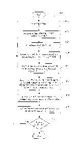
[00021] Referring now to FIG. 4, a flow diagram illustrates one embodiment of
a method
400 for implementing the present invention. The method 400 creates a surface
in a faulted space
using interpolation techniques. The method 400 in this example uses only well
tops across
faults to create the interpolated surface. The method 400 not only generates
sharp edges around
the faults, but also interpolates smoothly away from them.
[00022] In step 402, input data are stored using the client interface and/or
video interface
described in reference to FIG. 7. The input data may comprise well tops and
faults comprising
numerous fault segments. Each well top is preferably stored in KD tree, which
is a well known
data structure for fast and efficient retrieval of the input data. Each fault
segment is preferably
stored in a Quad tree, which is also a well known data structure used for fast
and efficient
retrieval.
[00023] In step 404, the surface level along both sides of each fault is
estimated. The
estimate is preferably done by finding each well top, which is stored as input
data in step 402, in
each fault block and interpolating the surface level along both sides of each
fault using one or
CA 02805036 2013-01-10
WO 2012/021119 PCT/US2010/044850
more, but not necessarily all, of the well tops found in each respective fault
block. Interpolation
is meant to encompass any well known interpolation technique such as, for
example, kriging,
collocated cokriging, simulation and collocated cosimulation algorithms. Each
fault throw,
which is defined as the amount of vertical displacement (i.e. elevation
change) between the
estimated surface levels, is stored as a value in the Quad tree data structure
described in
reference to step 402 with the estimated surface levels. As illustrated in
FIG. 5, which
represents an interpolated surface 500 using real input data in step 402, one
fault block is defined
by fault segments 502, 504, 506 and an edge 508 of the interpolated surface
500. Another fault
block is defined by fault segments 510, 512, 514 and 516. The real data used
for the interpolated
surface 500 includes 9,995 fault segments and 329 well tops, which are
illustrated within a 500
by 500 grid 540. A fault 501 includes fault segment 502 at one end of the
fault 501 and another
fault segment 514 toward another end of the fault 501. Each fault block may
contain one or
more well tops as demonstrated by the fault block containing well tops 518-
526. The fault block
defined by an edge 528 of the interpolated surface 500 and fault segments 530,
532 and 534 may
also contain one or more well tops. The surface level 538 along one side of
the fault 501
therefore, was estimated by i) finding each well top in the fault block
defined by fault segments
502, 504, 506 and the edge 508 of the interpolated surface 500; and ii)
kriging that surface level
using one or more of the well tops in the fault block. The surface level 536
along another side of
the fault 501 therefore, was estimated by i) find each well top in the fault
block defined by fault
segments 530, 532, 534 and the edge 528 of the interpolated surface 500; and
ii) kriging that
surface level using one or more of the well tops in the fault block. The
surface level on each side
of the fault 501 may be estimated in this manner (fault block by fault block)
from one end of the
fault 501 to another end of the fault 501. Alternatively, this step may begin
anywhere between
6
CA 02805036 2013-01-10
WO 2012/021119 PCT/US2010/044850
each end of the fault 501 and proceed in any manner or sequence until the
entire surface level on
each side of the fault 501 is estimated.
[00024] In step 406, each fault throw value is adjusted by i) smoothing the
surface levels
estimated in step 404 along each side of each fault that belong to the same
fault block; and ii)
tapering each fault throw value to zero at each distal end of each fault. The
tapering should not
effect a fault intersecting another fault and thus, necessarily occurs between
each distal end of a
fault and the closest point at which another fault intersects the fault.
[00025] In step 408, the local well tops within a predefined search
neighborhood from a
grid node are located using the well tops stored as input data in step 402,
regardless of whether
the local well tops cross fault segments and/or fault blocks. Each local well
top has a local well
top value that represents the surface level of that local well top. As
illustrated by the grid 540 in
FIG. 5, the local well tops within a predefined search neighborhood from grid
node 542 may or
may not include well tops 518-526 depending on the size of the predefined
search neighborhood.
The predefined search neighborhood may include any geometric shape, however,
is preferably
predefined by a radius from the grid node foiming a circular search
neighborhood.
[00026] In step 410, all faults that cross a vector between the grid node and
each
respective local well top located in step 408 are identified using the faults
stored in step 402.
Each vector between the grid node and each respective local well top located
in step 408
represents an intersecting vector.
[00027] In step 412, the adjusted fault throw values in step 406 are
accumulated (added
together) along each respective intersecting vector and the result represents
an accumulated fault
throw value for each respective intersecting vector. Because each intersecting
vector corres-
ponds with (intersects) a separate local well top and the accumulated fault
throw value represents
7
CA 02805036 2013-01-10
WO 2012/021119 PCT/US2010/044850
the adjusted fault throw values along each intersecting vector, each
accumulated fault throw
value may be different for each respective local well top.
[00028] In step 414, the value of each local well top found in step 408 is
adjusted based on
the accumulated fault throw value that corresponds with each intersecting
vector for a respective
local well top. Each adjusted local well top value therefore, is equal to the
value of the
respective local well top plus the accumulated fault throw value for the
intersecting vector that
intersects that respective local well top. As a result, the adjusted local
well top values
temporarily remove the local fault throw.
[00029] In step 416, interpolation is performed at the grid node using the
adjusted local
well top values from step 414. Interpolation is meant to encompass any well
known
interpolation technique such as, for example, kriging, collocated cokriging,
simulation and
collocated cosimulation algorithms. Optionally, other well known interpolation
techniques may
be used. In this manner, the new adjusted local well tops are interpolated
onto the grid.
[00030] In step 418, the method 400 determines whether there is another grid
node within
the grid. If there is not another grid node within the grid, then the method
400 ends. If there is
another grid node within the grid, then the method 400 returns to step 408 and
repeat steps 408,
410, 412, 414 and 416 for each grid node within the grid.
[00031] Although the fault network lying within the interpolated surface 500
in FIG. 5 is
complicated, the method 400 produced an interpolated surface 500 with fewer
artifacts around
the end of each fault when compared to other conventional methods. As
illustrated by the
comparison of FIG. 3 and FIG. 6, which illustrates a surface interpolated
according to method
400 using the same data used to produce the interpolated surface in FIG. 3,
the method 400
provides a significant improvement in reducing undesirable artifacts. For
example, the artifacts
8
CA 02805036 2013-01-10
WO 2012/021119 PCT/US2010/044850
302 located near the termination of the fault 304 in the interpolated surface
300 are not present
near the termination of the fault 604 in the interpolated surface 600 of FIG.
6. This approach
therefore, represents a substantial improvement for interpolating surfaces
having one or more
faults.
System Description
[00032] The present invention may be implemented through a computer-executable
program of instructions, such as program modules, generally referred to as
software applications
or application programs executed by a computer. The software may include, for
example,
routines, programs, objects, components, and data structures that perform
particular tasks or
implement particular abstract data types. The software forms an interface to
allow a computer to
react according to a source of input. DecisionSpaceTm, which is a commercial
software
application marketed by Landmark Graphics Corporation, may be used as an
interface
application to implement the present invention. The software may also
cooperate with other
code segments to initiate a variety of tasks in response to data received in
conjunction with the
source of the received data. The software may be stored and/or carried on any
variety of
memory media such as CD-ROM, magnetic disk, bubble memory and semiconductor
memory
(e.g., various types of RAM or ROM). Furthermore, the software and its results
may be
transmitted over a variety of carrier media such as optical fiber, metallic
wire and/or through any
of a variety of networks such as the Internet.
[00033] Moreover, those skilled in the art will appreciate that the invention
may be
practiced with a variety of computer-system configurations, including hand-
held devices,
multiprocessor systems, microprocessor-based or programmable-consumer
electronics,
minicomputers, mainframe computers, and the like. Any number of computer-
systems and
9
CA 02805036 2013-01-10
WO 2012/021119 PCT/US2010/044850
computer networks are acceptable for use with the present invention. The
invention may be
practiced in distributed-computing environments where tasks are performed by
remote-
processing devices that are linked through a communications network. In a
distributed-
computing environment, program modules may be located in both local and remote
computer-
storage media including memory storage devices. The present invention may
therefore, be
implemented in connection with various hardware, software or a combination
thereof, in a
computer system or other processing system.
[00034] Referring now to FIG. 7, a block diagram of a system for implementing
the
present invention on a computer is illustrated. The system includes a
computing unit, sometimes
referred to a computing system, which contains memory, application programs, a
client interface,
a video interface and a processing unit. The computing unit is only one
example of a suitable
computing environment and is not intended to suggest any limitation as to the
scope of use or
functionality of the invention.
[00035] The memory primarily stores the application programs, which may also
be
described as program modules containing computer-executable instructions,
executed by the
computing unit for implementing the present invention described herein and
illustrated in FIGS.
4-6. The memory therefore, primarily includes a surface interpolation module,
which performs
steps 402-418 illustrated in FIG. 4. Although DecisionSpaceTM may be used to
interface with
the surface interpolation module to perform steps 402-418, other interface
applications may be
used instead of DecisionSpaceTM or the surface interpolation module may be
used as a stand
alone application. DecisionSpaceTm provides a common interface for the surface
interpolation
module and other applications and/or modules illustrated in FIG. 7. It allows
the user to access
data, view it in 1D, 2D and 3D viewers and perform various types of data
interpretation and
CA 02805036 2013-01-10
WO 2012/021119 PCT/US2010/044850
computations. The surface interpolation module is currently configured to be
implemented
through the Dynamic GeomodelingTM module in DecisionSpaceTM as illustrated in
FIG. 7.
[00036] Although the computing unit is shown as having a generalized memory,
the
computing unit typically includes a variety of computer readable media. By way
of example,
and not limitation, computer readable media may comprise computer storage
media. The
computing system memory may include computer storage media in the form of
volatile and/or
nonvolatile memory such as a read only memory (ROM) and random access memory
(RAM). A
basic input/output system (BIOS), containing the basic routines that help to
transfer information
between elements within the computing unit, such as during start-up, is
typically stored in ROM.
The RAM typically contains data and/or program modules that are immediately
accessible to
and/or presently being operated on by the processing unit. By way of example,
and not
limitation, the computing unit includes an operating system, application
programs, other program
modules, and program data.
[00037] The components shown in the memory may also be included in other
removable/nonremovable, volatile/nonvolatile computer storage media or they
may be
implemented in the computing unit through application program interface
("API"), which may
reside on a separate computing unit connected through a computer system or
network. For
example only, a hard disk drive may read from or write to nonremovable,
nonvolatile magnetic
media, a magnetic disk drive may read from or write to a removable, non-
volatile magnetic disk,
and an optical disk drive may read from or write to a removable, nonvolatile
optical disk such as
a CD ROM or other optical media. Other removable/non-removable, volatile/non-
volatile
computer storage media that can be used in the exemplary operating environment
may include,
but are not limited to, magnetic tape cassettes, flash memory cards, digital
versatile disks, digital
11
CA 02805036 2013-01-10
WO 2012/021119 PCT/US2010/044850
video tape, solid state RAM, solid state ROM, and the like. The drives and
their associated
computer storage media discussed above provide storage of computer readable
instructions, data
structures, program modules and other data for the computing unit.
[00038] A client may enter commands and information into the computing unit
through
the client interface, which may be input devices such as a keyboard and
pointing device,
commonly referred to as a mouse, trackball or touch pad. Input devices may
include a
microphone, joystick, satellite dish, scanner, or the like. These and other
input devices are often
connected to the processing unit through a system bus, but may be connected by
other interface
and bus structures, such as a parallel port or a universal serial bus (USB).
[00039] A monitor or other type of display device may be connected to the
system bus via
an interface, such as a video interface. A graphical user interface ("GUI")
may also be used with
the video interface to receive instructions from the client interface and
transmit instructions to
the processing unit. In addition to the monitor, computers may also include
other peripheral
output devices such as speakers and printer, which may be connected through an
output
peripheral interface.
[00040] Although many other internal components of the computing unit are not
shown,
those of ordinary skill in the art will appreciate that such components and
their interconnection
are well known.
12