Note: Descriptions are shown in the official language in which they were submitted.
CA 02805102 2013-01-10
WO 2012/021412 PCT/US2011/046815
TITLE OF THE INVENTION
SYSTEM AND METHOD FOR MEASURING PRESSURE
APPLIED BY A PIEZO-ELECTRIC PUMP
CROSS-REFERENCE TO RELATED APPLICATIONS
[0001] This application claims the benefit of U.S. Provisional Application No.
61/371,954, filed August 9, 2010, and is hereby incorporated by reference.
BACKGROUND
1. Field of the Invention
[0002] The illustrative embodiments of the invention relate generally to a
pump for
fluid and, more specifically, to a pump in which the pumping cavity is
substantially elliptical
in shape having end walls and a side wall with an actuator disposed between
the end walls.
The illustrative embodiments of the invention relate more specifically to a
disc pump having a
valve mounted in the actuator and/or one additional valve mounted in one of
the end walls.
2. Description of Related Art
[0003] The generation of high amplitude pressure oscillations in closed
cavities has
received significant attention in the fields of thermo-acoustics and pump type
compressors.
Recent developments in non-linear acoustics have allowed the generation of
pressure waves
with higher amplitudes than previously thought possible.
[0004] It is known to use acoustic resonance to achieve fluid pumping from
defined
inlets and outlets. This can be achieved using a elliptical cavity with an
acoustic driver at one
end, which drives an acoustic standing wave. In such a elliptical cavity, the
acoustic pressure
wave has limited amplitude. Varying cross-section cavities, such as cone, horn-
cone, bulb
have been used to achieve high amplitude pressure oscillations thereby
significantly increasing
the pumping effect. In such high amplitude waves the non-linear mechanisms
with energy
dissipation have been suppressed. However, high amplitude acoustic resonance
has not been
employed within disc-shaped cavities in which radial pressure oscillations are
excited until
recently. International Patent Application No. PCT/GB2006/001487, published as
WO
1
CA 02805102 2013-01-10
WO 2012/021412 PCT/US2011/046815
2006/111775, discloses a pump having a substantially disc-shaped cavity with a
high aspect
ratio, i.e., the ratio of the radius of the cavity to the height of the
cavity.
[0005] Such a pump has a substantially elliptical cavity comprising a side
wall closed
at each end by end walls. The pump also comprises an actuator that drives
either one of the
end walls to oscillate in a direction substantially perpendicular to the
surface of the driven end
wall. The spatial profile of the motion of the driven end wall is described as
being matched to
the spatial profile of the fluid pressure oscillations within the cavity, a
state described herein as
mode-matching. When the pump is mode-matched, work done by the actuator on the
fluid in
the cavity adds constructively across the driven end wall surface, thereby
enhancing the
amplitude of the pressure oscillation in the cavity and delivering high pump
efficiency. The
efficiency of a mode-matched pump is dependent upon the interface between the
driven end
wall and the side wall. It is desirable to maintain the efficiency of such
pump by structuring
the interface so that it does not decrease or dampen the motion of the driven
end wall thereby
mitigating any reduction in the amplitude of the fluid pressure oscillations
within the cavity.
[0006] The actuator of the pump described above causes an oscillatory motion
of the
driven end wall ("displacement oscillations") in a direction substantially
perpendicular to the
end wall or substantially parallel to the longitudinal axis of the elliptical
cavity, referred to
hereinafter as "axial oscillations" of the driven end wall within the cavity.
The axial
oscillations of the driven end wall generate substantially proportional
"pressure oscillations"
of fluid within the cavity creating a radial pressure distribution
approximating that of a Bessel
function of the first kind as described in International Patent Application
No.
PCT/GB2006/001487 which is incorporated by reference herein, such oscillations
referred to
hereinafter as "radial oscillations" of the fluid pressure within the cavity.
A portion of the
driven end wall between the actuator and the side wall provides an interface
with the side wall
of the pump that decreases dampening of the displacement oscillations to
mitigate any
reduction of the pressure oscillations within the cavity, that portion being
referred to
hereinafter as an "skirt" or a "skirt" as described more specifically in U.S.
Patent Application
No. 12/477,594 which is incorporated by reference herein. The illustrative
embodiments of
the skirt are operatively associated with the peripheral portion of the driven
end wall to reduce
dampening of the displacement oscillations.
[0007] Such pumps also require one or more valves for controlling the flow of
fluid
through the pump and, more specifically, valves being capable of operating at
high
2
CA 02805102 2013-01-10
WO 2012/021412 PCT/US2011/046815
frequencies. Conventional valves typically operate at lower frequencies below
500 Hz for a
variety of applications. For example, many conventional compressors typically
operate at 50
or 60 Hz. Linear resonance compressors known in the art operate between 150
and 350 Hz.
However, many portable electronic devices including medical devices require
pumps for
delivering a positive or negative pressure that are relatively small in size
and quiet during
operation so as to provide discrete therapy. To achieve these objectives, such
pumps must
operate at very high frequencies requiring valves capable of operating at
about 20 kHz and
higher. To operate at these high frequencies, the valve must be responsive to
a high frequency
oscillating pressure that can be rectified to create a net flow of fluid
through the pump.
[0008] Such a valve is described more specifically in International Patent
Application
No. PCT/GB2009/050614 which is incorporated by reference herein. Valves may be
disposed
in either the first or second aperture, or both apertures, for controlling the
flow of fluid through
the pump. Each valve comprises a first plate having apertures extending
generally
perpendicular therethrough and a second plate also having apertures extending
generally
perpendicular therethrough, wherein the apertures of the second plate are
substantially offset
from the apertures of the first plate. The valve further comprises a sidewall
disposed between
the first and second plate, wherein the sidewall is closed around the
perimeter of the first and
second plates to form a cavity between the first and second plates in fluid
communication with
the apertures of the first and second plates. The valve further comprises a
flap disposed and
moveable between the first and second plates, wherein the flap has apertures
substantially
offset from the apertures of the first plate and substantially aligned with
the apertures of the
second plate. The flap is motivated between the first and second plates in
response to a
change in direction of the differential pressure of the fluid across the
valve.
3
CA 02805102 2013-01-10
WO 2012/021412 PCT/US2011/046815
BRIEF SUMMARY OF THE INVENTION
[0009] In addressing measurement and control issues of tissue treatment
systems,
which may include a disc pump or micro-pump, the principles of the present
invention may be
utilized to measure the pressure being generated by the disc pump to more
effectively and
economically control the operation of the disc pump. The disc pump includes an
actuator that
vibrates within a cavity to generate a radial pressure wave to provide a
reduced pressure for
application to a load or tissue site as described above. Displacement of the
actuator may be
measured using one or more sensors. Pressure being generated by the disc pump
for the tissue
site may be determined in response to the measured displacement of the
actuator. A drive
signal for the actuator may be adjusted to control operation and,
consequently, displacement of
the actuator to reach a desired pressure at the tissue site.
[0010] One embodiment of a disc pump includes a disc pump housing, skirt,
actuator,
sensor, and electronic circuit. The skirt is fixed to the disc pump housing to
support the
actuator, and may be any material that is sufficiently flexible to allow the
actuator to vibrate.
The actuator and the skirt face an opposing base plate to form a cavity within
the disc pump
wherein radial pressure waves are generated. The actuator may have a first
surface and a
second surface and be directly or indirectly coupled to the skirt. The sensor
may be positioned
outside the cavity to sense a position of the actuator with respect to the
disc pump housing that
corresponds to the pressure being provided. An electronic circuit may be in
communication
with the sensor and be configured to calculate pressure provided by the disc
pump as a
function of the position of the actuator with respect to the disc pump housing
while the
actuator is activated.
[0011] In another embodiment, a pump body comprises a substantially elliptical
shaped side wall closed at one end by a base wall and the other end by a pair
of interior plates
to form a cavity within said pump body for containing a fluid wherein a first
one of the interior
plates adjacent the cavity includes a center portion and a peripheral portion.
The pump further
comprises an actuator formed by the end plates wherein the second one of the
interior plates is
operatively associated with the central portion of the first interior plate to
cause an oscillatory
displacement motion thereby generating radial pressure oscillations of the
fluid within the
cavity in response to a drive signal being applied to said actuator when in
use. The pump also
comprises a skirt flexibly connected between the side wall and the peripheral
portion of the
4
WO 2012/021412 CA 02805102 2013-01-10 PCT/US2011/046815
first interior plate to facilitate the oscillatory displacement motion. The
pump also comprises a
first aperture extending through said actuator to enable fluid to flow through
the cavity and a
second aperture extending through the base wall to enable fluid to flow
through the cavity. A
valve is disposed in at least one of said first aperture and second apertures
and is adapted to
permit the fluid to flow through the cavity in substantially one direction to
pressurize or
depressurize a load as fluid begins flowing through the cavity, thereby
causing said actuator to
move toward the base wall from a rest position to a biased position with
increasing pressure
and flexing of the skirt. The pump further comprises a sensor mounted outside
the cavity in a
fixed position with respect to said pump body for measuring the displacement
of said actuator
at any position between the rest position and the biased position as fluid
begins flowing
through the cavity to pressurize or depressurize the load.
[0012] One method for controlling a disc pump includes driving an actuator
within a
housing of a disc pump using a drive signal. The actuator is mounted within
the disc pump by
the skirt which is flexible. As the actuator vibrates in response to the drive
signal, the pressure
created in a load increases while airflow decreases from a free-flow state to
a stall state. The
pressure being built up in the load by the disc pump may be measured by a
sensor as a
function of the displacement of the actuator from a rest position in the free-
flow state to a
biased position in the stall state when the pressure forces the actuator away
from the rest
position as the skirt flexes with the actuator from its fixed position toward
the biased position.
Because the actuator generates radial pressure waves within the cavity of the
disc pump, such
a sensor is preferably positioned outside the cavity of the disc pump so that
it does not
interfere with the operation of the disc pump itself.
[0013] Other objects, features, and advantages of the illustrative embodiments
are
disclosed herein and will become apparent with reference to the drawings and
detailed
description that follow.
5
WO 2012/021412 CA 02805102 2013-01-10 PCT/US2011/046815
BRIEF DESCRIPTION OF THE DRAWINGS
[0014] Illustrative embodiments of the present invention are described in
detail below
with reference to the attached drawing figures, which are incorporated by
reference herein and
wherein:
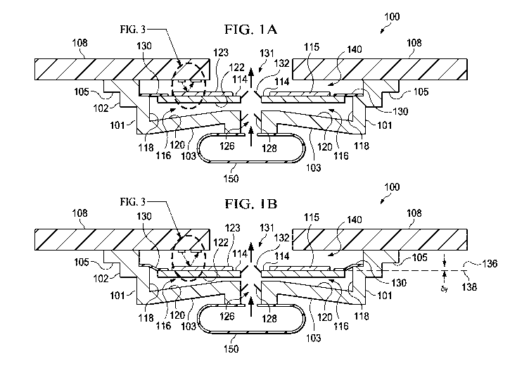
[0015] FIG. lA is a schematic, cross-sectional view of a first disc pump
having an
actuator shown in a rest position according to a first illustrative
embodiment;
[0016] FIG. 1B is a schematic, cross-sectional view of the first disc pump
showing the
actuator in a biased position according to a first illustrative embodiment;
[0017] FIG. 2A is a graph of the axial displacement oscillations for a
fundamental
bending mode of the actuator of the first disc pump;
[0018] FIG. 2B is a graph of the pressure oscillations of fluid within the
cavity of the
first disc pump in response to the bending mode shown in FIG. 2A;
[0019] FIG. 3 is a zoomed-in view of a first sensor for measuring the
displacement of
the actuator of the first disc pump according to a first illustrative
embodiment;
[0020] FIG. 4 is a schematic view of an illustrative receiver of the first
sensor
indicating the position of the actuator when in the rest position and the
biased position;
[0021] FIG. 5 is a schematic, cross-sectional view of the disc pump with the
actuator
shown in the biased position including a zoomed-in view of a second sensor for
measuring the
displacement of the actuator according to a second illustrative embodiment;
[0022] FIG. 6 is a third illustrative sensor including a diffraction grating
for measuring
displacement of an actuator in a disc pump;
[0023] FIG. 7 is a fourth illustrative sensor including a magnetic element for
measuring displacement of an actuator in a disc pump;
[0024] FIG. 8 is a block diagram of an illustrative circuit of a disc pump for
measuring
and controlling a reduced pressure generated by the disc pump; and
[0025] FIG. 9 is a flow chart of an illustrative process for controlling
pressure
generated by a disc pump.
6
WO 2012/021412 CA 02805102 2013-01-10 PCT/US2011/046815
DETAILED DESCRIPTION OF THE PREFERRED EMBODIMENT
[0026] FIGS. lA and 1B are illustrations of a cross-section view of an
illustrative disc
pump 100 in accordance with illustrative embodiments. As shown, the disc pump
100 may
include a pump housing 102 having a substantially elliptical shape including a
elliptical wall
101 closed at one end by a base wall 103 and mounted at the other end by legs
105 attached to
a circuit board 108 or other substrate to support the pump housing 102. The
elliptical wall
101, the legs 105, and base wall 103 together form the pump housing 102. The
pump 100
further comprises a pair of disc-shaped interior plates 114, 115 supported
within the pump 100
by a ring-shaped skirt 130 affixed to the elliptical wall 101 of the pump
body. The internal
surfaces of the elliptical wall 101, the base wall 103, the interior plate
114, and the ring-shaped
skirt 130 form a cavity 116 within the pump 100. The internal surfaces of the
cavity 116
comprise a side wall 118 which is a first portion of the inside surface of the
elliptical wall 101
that is closed at one end by end wall 120 wherein the end wall 120 is the
internal surface of the
end plate 103 and the end wall 122 comprises the internal surface of the
interior plate 114 and
a first side of the skirt 130. The end wall 122 thus comprises a central
portion corresponding
to the inside surface of the interior plate 114 and a peripheral portion
corresponding to the
inside surface of the ring-shaped skirt 130.
[0027] Although the pump 100 and its components are substantially elliptical
in shape,
the specific embodiment disclosed herein is a circular, elliptical shape. In
the embodiments
shown in FIGS. lA and 1B, the end wall 120 is shown as being a frusto-conical
surface, but
may also be generally planar and parallel with the end wall 122. The base wall
103 and
elliptical wall 101 of the pump body may be formed from any suitable rigid
material
including, without limitation, metal, ceramic, glass, or plastic including,
without limitation,
injection-molded plastic.
[0028] The interior plates 114, 115 of the pump 100 together form an actuator
140 that
is operatively associated with the central portion of the end wall 122 which
is one of the
internal surfaces of the cavity 116. One of the interior plates 114, 115 must
be formed of a
piezoelectric material which may include any electrically active material that
exhibits strain in
response to an applied electrical signal, such as, for example, an electro-
strictive or magneto-
strictive material. In one preferred embodiment, for example, the interior
plate 115 is formed
of piezoelectric material that that exhibits strain in response to an applied
electrical signal, i.e.,
the active interior plate. The other one of the interior plates 114, 115
preferably possess a
7
CA 02805102 2013-01-10
WO 2012/021412 PCT/US2011/046815
bending stiffness similar to the active interior plate and may be formed of a
piezoelectric
material or an electrically inactive material, such as a metal or ceramic. In
this preferred
embodiment, the interior plate 114 possess a bending stifthess similar to the
active interior
plate 115 and is formed of an electrically inactive material, such as a metal
or ceramic, i.e., the
inert interior plate. When the active interior plate 115 is excited by an
electrical current, the
active interior plate 115 expands and contracts in a radial direction relative
to the longitudinal
axis of the cavity 116 causing the interior plates 114, 115 to bend, thereby
inducing an axial
deflection of their respective end wall 122 in a direction substantially
perpendicular to the end
wall 122 (See FIG. 2A).
[0029] In other embodiments not shown, the skirt 130 may support either one of
the
interior plates 114, 115, whether the active or inert internal plate, from the
top or the bottom
surfaces depending on the specific design and orientation of the pump 100. In
another
embodiment, the actuator 140 may be replaced by a device in a force-
transmitting relation
with only one of the interior plates 114, 115 such as, for example, a
mechanical, magnetic or
electrostatic device, wherein the interior plate may be formed as an
electrically inactive or
passive layer of material driven into oscillation by such device (not shown)
in the same
manner as described above.
[0030] The pump 100 further comprises at least two apertures extending from
the
cavity 116 to the outside of the pump 100, wherein at least one of the
apertures contains a
valve to control the flow of fluid through the aperture. Although the
apertures may be located
at any position in the cavity 116 where the actuator 140 generates a pressure
differential as
described below in more detail, one preferred embodiment of the pump 100
comprises
aperture 126 located at approximately the centre of and extending through the
base wall 103.
The aperture 126 contains at least one end valve. In one preferred embodiment,
the aperture
126 contains a valve 128 which regulates the flow of fluid in one direction as
indicated by the
arrow. Thus, for this embodiment, the valve 128 functions as an inlet valve
for the pump.
[0031] The pump 100 further comprises at least one aperture from the cavity
116
through the actuator 140, wherein at least one of the apertures contains a
valve to control the
flow of fluid through the aperture. Although these apertures may be located at
any position on
the actuator 140 from the cavity 116 where the actuator 140 generates a
pressure differential as
described below in more detail, one embodiment of the pump 100 comprises a
single aperture
131 located at approximately the centre of and extending through the interior
plates 114, 115 .
8
CA 02805102 2013-01-10
WO 2012/021412 PCT/US2011/046815
The aperture 131 contains an actuator valve 132 which regulates the flow of
fluid in one
direction from the cavity 116 as indicated by the arrow so that the actuator
valve 132 functions
as an outlet valve from the cavity 116. The actuator valve 132 enhances the
output of the
pump 100 by supplementing the operation of the inlet valve 128 as described in
more detail
below.
[0032] The dimensions of the cavity 116 described herein should preferably
satisfy
certain inequalities with respect to the relationship between the height (h)
and radius (r) of the
cavity 116 which is the distance from the longitudinal axis of the cavity 116
to the side wall
118. These equations are as follows:
r/h > 1.2; and
h2/r > 4x10-16 meters.
[0033] In one embodiment of the invention, the ratio of the cavity radius to
the cavity
height (r/h) is between about 10 and about 50 when the fluid within the cavity
116 is a gas. In
this example, the volume of the cavity 116 may be less than about 10 ml.
Additionally, the
ratio of h2/r is preferably within a range between about 10-6 and about 10-
7meters where the
working fluid is a gas as opposed to a liquid.
[0034] Additionally, the cavity 116 disclosed herein should preferably satisfy
the
following inequality relating the cavity radius (r) and operating frequency
(f) which is the
frequency at which the actuator 140 vibrates to generate the axial
displacement of the end wall
122. The inequality equation is as follows:
k (c ) k (c )
0 s<r<0 f
[0035]
27-tf 27-tf
[Equation 1]
wherein the speed of sound in the working fluid within the cavity 116 (c) may
range between a
slow speed (cs) of about 115 m/s and a fast speed (cf) equal to about 1,970
m/s as expressed in
the equation above, and k0 is a constant (ko = 3.83). The frequency of the
oscillatory motion
of the actuator 140 is preferably about equal to the lowest resonant frequency
of radial
pressure oscillations in the cavity 116 , but may be within 20% that value.
The lowest
resonant frequency of radial pressure oscillations in the cavity 116 is
preferably greater than
about 500 Hz.
[0036] Although it is preferable that the cavity 116 disclosed herein should
satisfy
individually the inequalities identified above, the relative dimensions of the
cavity 116 should
not be limited to cavities having the same height and radius. For example, the
cavity 116 may
9
CA 02805102 2013-01-10
WO 2012/021412 PCT/US2011/046815
have a slightly different shape requiring different radii or heights creating
different frequency
responses so that the cavity 116 resonates in a desired fashion to generate
the optimal output
from the pump 100.
[0037] In operation, the pump 100 may function as a source of positive
pressure
adjacent the outlet valve 132 to pressurize a load (not shown) or as a source
of negative or
reduced pressure adjacent the inlet valve 128 to depressurize a load 150 as
illustrated by the
arrows. The inlet of the pump 100 as shown is in fluid communication with the
load 150 such
that the pump 100 functions as a source of negative or reduced pressure
adjacent the inlet
valve 128. The load 150 may be a tissue treatment system that utilizes
negative pressure for
treatment. The term "reduced pressure" as used herein generally refers to a
pressure less than
the ambient pressure where the pump 100 is located. Although the term "vacuum"
and
"negative pressure" may be used to describe the reduced pressure, the actual
pressure
reduction may be significantly less than the pressure reduction normally
associated with a
complete vacuum. The pressure is "negative" in the sense that it is a gauge
pressure, i.e., the
pressure is reduced below ambient atmospheric pressure. Unless otherwise
indicated, values
of pressure stated herein are gauge pressures. References to increases in
reduced pressure
typically refer to a decrease in absolute pressure, while decreases in reduced
pressure typically
refer to an increase in absolute pressure.
[0038] FIG. 2A shows one possible displacement profile illustrating the axial
oscillation of the driven end wall 122 of the cavity 116. The solid curved
line and arrows
represent the displacement of the driven end wall 122 at one point in time,
and the dashed
curved line represents the displacement of the driven end wall 122 one half-
cycle later. The
displacement as shown in this figure and the other figures is exaggerated.
Because the
actuator 140 is not rigidly mounted at its perimeter, but rather suspended by
the ring-shaped
skirt 130, the actuator 140 is free to oscillate about its centre of mass in
its fundamental mode.
In this fundamental mode, the amplitude of the displacement oscillations of
the actuator 140 is
substantially zero at an annular displacement node 42 located between the
centre of the driven
end wall 122 and the side wall 118. The amplitudes of the displacement
oscillations at other
points on the end wall 122 are greater than zero as represented by the
vertical arrows. A
central displacement anti-node 43 exists near the centre of the actuator 140
and a peripheral
displacement anti-node 43' exists near the perimeter of the actuator 140. The
central
displacement anti-node 43 is represented by the dashed curve after one half-
cycle.
10
CA 02805102 2013-01-10
WO 2012/021412 PCT/US2011/046815
[0039] FIG. 2B shows one possible pressure oscillation profile illustrating
the pressure
oscillation within the cavity 116 resulting from the axial displacement
oscillations shown in
FIG. 2A. The solid curved line and arrows represent the pressure at one point
in time. In this
mode and higher-order modes, the amplitude of the pressure oscillations has a
positive central
pressure anti-node 45 near the centre of the cavity 116 and a peripheral
pressure anti-node 45'
near the side wall 118 of the cavity 116. The amplitude of the pressure
oscillations is
substantially zero at the annular pressure node 44 between the central
pressure anti-node 45
and the peripheral pressure anti-node 45'. At the same time, the amplitude of
the pressure
oscillations as represented by the dashed line has a negative central pressure
anti-node 47 near
the centre of the cavity 116 with a peripheral pressure anti-node 47' and the
same annular
pressure node 44. For a elliptical cavity, the radial dependence of the
amplitude of the
pressure oscillations in the cavity 116 may be approximated by a Bessel
function of the first
kind. The pressure oscillations described above result from the radial
movement of the fluid
in the cavity 116 and so will be referred to as the "radial pressure
oscillations" of the fluid
within the cavity 116 as distinguished from the axial displacement
oscillations of the actuator
140.
[0040] With further reference to FIGS. 2A and 2B, it can be seen that the
radial
dependence of the amplitude of the axial displacement oscillations of the
actuator 140 (the
"mode-shape" of the actuator 140) approximates a Bessel function of the first
kind so as to
match more closely the radial dependence of the amplitude of the desired
pressure oscillations
in the cavity 116 (the "mode-shape" of the pressure oscillation). Other
symmetric and
asymmetric functions may also be used to generate pressure oscillations within
the cavity 116.
In any event, by not rigidly mounting the actuator 140 at its perimeter and
allowing it to
vibrate more freely about its centre of mass, the mode-shape of the
displacement oscillations
substantially matches the mode-shape of the pressure oscillations in the
cavity 116 thus
achieving mode-shape matching or, more simply, mode-matching. Although the
mode-
matching may not always be perfect in this respect, the axial displacement
oscillations of the
actuator 140 and the corresponding pressure oscillations in the cavity 116
have substantially
the same relative phase across the full surface of the actuator 140 wherein
the radial position
of the annular pressure node 44 of the pressure oscillations in the cavity 116
and the radial
position of the annular displacement node 42 of the axial displacement
oscillations of actuator
140 are substantially coincident.
11
WO 2012/021412 CA 02805102 2013-01-10PCT/US2011/046815
[0041] As the actuator 140 vibrates about its centre of mass, the radial
position of the
annular displacement node 42 will necessarily lie inside the radius of the
actuator 140 when
the actuator 140 vibrates in its fundamental bending mode as illustrated in
FIG. 2A. Thus, to
ensure that the annular displacement node 42 is coincident with the annular
pressure node 44,
the radius of the actuator (ract) should preferably be greater than the radius
of the annular
pressure node 44 to optimize mode-matching. Assuming again that the pressure
oscillation in
the cavity 116 approximates a Bessel function of the first kind, the radius of
the annular
pressure node 44 would be approximately 0.63 of the radius from the centre of
the end wall
122 to the side wall 118, i.e., the radius of the cavity 116 ("r"). Therefore,
the radius of the
actuator 140 (ract) should preferably satisfy the following inequality: ract
0.63r.
[0042] The ring-shaped skirt 130 may be a flexible membrane which enables the
edge
of the actuator 140 to move more freely as described above by bending and
stretching in
response to the vibration of the actuator 140 as shown by the displacement at
the peripheral
displacement anti-node 43'. The flexible membrane overcomes the potential
dampening
effects of the side wall 118 on the actuator 140 by providing a low mechanical
impedance
support between the actuator 140 and the elliptical wall 101 of the pump 100
thereby reducing
the dampening of the axial oscillations at the peripheral displacement anti-
node 43' of the
actuator 140. Essentially, the flexible membrane minimizes the energy being
transferred from
the actuator 140 to the side wall 118 with the outer peripheral edge of the
flexible membrane
remaining substantially stationary. Consequently, the annular displacement
node 42 will
remain substantially aligned with the annular pressure node 44 so as to
maintain the mode-
matching condition of the pump 100. Thus, the axial displacement oscillations
of the driven
end wall 122 continue to efficiently generate oscillations of the pressure
within the cavity 116
from the central pressure anti-nodes 45, 47 to the peripheral pressure anti-
nodes 45', 47' at the
side wall 118 as shown in FIG. 2B.
[0043] As the actuator 140 vibrates in response to the drive signal, the
pressure created
in the load 150 increases while airflow decreases from a free-flow state to a
stall state. The
pressure being built up in the load 150 by the disc pump 100 may be measured
by a sensor as a
function of the displacement (6y) of the actuator 140 from a rest position 136
in the free-flow
state as shown in FIG. lA to a biased position 138 in the stall state as shown
in FIG. 1B when
the pressure forces the actuator 140 away from the rest position as the skirt
130 flexes with the
actuator 140 from its fixed position at the side wall 101 toward the biased
position 138.
12
CA 02805102 2013-01-10
WO 2012/021412 PCT/US2011/046815
Because the actuator 140 generates radial pressure waves within the cavity 116
of the disc
pump 100, such a sensor is preferably positioned outside the cavity 116 of the
disc pump 100
so that it does not interfere with the operation of the disc pump 100.
[0044] FIG. 3 is a zoomed-in view of a sensor 331 mounted on the circuit board
108 to
face the actuator 140 and measure the displacement of the actuator 140 of the
disc pump 100.
The sensor 33 1 includes an optical transmitter 332 and optical receiver 334
for use in
measuring displacement 130 of the actuator 140. The optical transmitter 332
communicates
an optical signal 335 that may be a light wave in a visible or non-visible
spectrum. The optical
signal 335 is reflected off the surface of the interior plate 115 of the
actuator 140 so that the
reflected signal is received by the optical receiver 334 regardless of the
displacement (4) of
the actuator 140 as shown in FIG. 4. When the actuator 140 is in the rest
position 136, a first
reflected signal 340 impinges on the optical receiver 334 at the position
shown in both FIGS. 3
and 4. As the actuator 140 is displaced from the rest position 136 to the
biased position 138,
the first reflected signal 340 is correspondingly displaced by a corresponding
reflected
displacement (x) as a second reflected signal 342 depending on the
displacement (y) of the
actuator 140. Essentially, the image of the reflected signals that impinge on
the optical
receiver 334 follow a path from the rest position 136 to the fully biased
position 138 as shown
in FIG. 4. The reflected displacement (x) is proportional to the displacement
(6y) of the
actuator 140 which is a function of the pressure provided by the disc pump 100
as described
above.
[0045] In one embodiment, the optical transmitter 332 may be a laser, a light
emitting
diode (LED), a vertical cavity surface emitting laser (VCSEL), or light
emitting element. The
optical transmitter 332 may be positioned on the circuit board 108 and
oriented to reflect the
optical signal 335 off any point of the interior plate 115 of the actuator 140
as long as that the
first reflected signal 340 and the second reflected signal 342 are still
received and measured by
the optical sensor 334. However, as the actuator 140 oscillates in a
fundamental mode to
generate airflow as described and shown in FIG. 2A, the amplitude of the
displacement
oscillations of the actuator 140 may be substantially zero at any annular
displacement nodes
42 that are generated. Correspondingly, the amplitudes of the displacement
oscillations at
other points along the actuator 140 are greater than zero as also described.
Therefore, the
optical transmitter 332 should be positioned and oriented so that the optical
signal 335 is
reflected from a position close to the annular displacement nodes 42 to
minimize the effect of
13
WO 2012/021412 CA 02805102
2013-01-10
PCT/US2011/046815
the high frequency oscillations of the actuator 140 and more accurately
measure the
displacement (6y) of the actuator 140 as it moves more slowly from the rest
position 136 to the
biased position 138.
[0046] In one embodiment, the optical sensor 334 may include multiple pixels
forming
a sensor array. The optical sensor 334 may be configured to sense the position
of one or more
reflected beams at one or more wavelengths. As a result, the optical receiver
334 may be
configured to sense the reflected displacement (6x) 144 between the first
reflected signal 340
and the second reflected signal 342. The optical receiver 334 may be
configured to convert
the reflected signals 340 and 342 sensed by the optical receiver 334 into
electrical signals by
the respective pixels of the optical receiver 334. The reflected displacement
(6x) may be
measured or calculated in real-time or utilizing a specified sampling
frequency to determine
the position of the actuator 140 relative to the pump housing 102. In one
embodiment, the
position of the actuator 140 is computed as an average or mean position over a
given time
period. Pixels of the optical receiver 334 may be sized to provide additional
sensitivity to
detect relatively small displacements (6y) of the actuator 140 to better
monitor the pressure
being provided by the disc pump 100 so that it can be controlled in real-time.
[0047] Alternative methods of computing the displacement of the actuator 140
may be
utilized in accordance with the principles of the present invention. It should
be understood
that determining the displacement of the actuator 140 may be accomplished
relative to any
other fixed-position element in the pump housing 102. Although generally
substantially
proportional, the reflected displacement (x) may equal the displacement (6y)
of the actuator
140 multiplied by a scale factor where the scale factor may be predetermined
value based in
the configuration of the pump housing 102 of the disc pump 100 or other
alignment factors.
As a result, the reduced pressure within the cavity 116 of the disc pump 100
may be
determined by sensing the displacement (y) of the actuator 140 without the
need for pressure
sensors that directly measure the pressure provided to a load, but are too
bulky and expensive
for measuring the pressure provided by the disc pump 100 in a reduced pressure
system for
example. The illustrative embodiments optimize the utilization of space within
the pump
housing 102 without interfering with the pressure oscillations being created
within the cavity
116 of the disc pump 100.
[0048] FIG. 5 is another schematic, cross-sectional view of the disc pump 100
showing
the actuator 140 in the biased position 138 including a assumed-in view of
another sensor for14
WO 2012/021412 CA 02805102 2013-01-10PCT/US2011/046815
measuring the displacement of the actuator 140 according to another
illustrative embodiment.
The sensor is an ultrasonic transceiver 546 that transmits ultrasonic waves
548 to determine
the position of the actuator 140 based on the ultrasonic waves 548 reflected
by the actuator
140 and received by the ultrasonic transceiver 546. For purposes of
simplicity, the ultrasonic
waves that echo back to the ultrasonic transceiver 546 are not shown. The
ultrasonic
transceiver 546 may send raw measurements or processed data regarding the
displacement
(6y) of the actuator 140 to one or more electronic devices including, for
example, a processor
to determine the reduced pressure generated by the this pump 100 and other
operational
characteristics.
[0049] With regard to FIG. 6, a diffraction grating 602 for measuring
displacement
(6y) of the actuator 140 in the disc pump 100 is shown. The diffraction
grating 602 may be
attached to or integrated with the actuator 140. For example, the diffraction
grating 602 may
be a reflective optical element attached to or the actuator 140 with adhesives
or other fastening
means during manufacturing of the disc pump. As shown, a transmitter 607
transmits a multi-
spectral optical signal 608 onto the diffraction grating 602. The diffraction
grating 602
diffracts the multi-spectral optical signal 608 into several beams with
different wavelengths
kl, k2, k3, and ?A. The wavelengths of beams kl, k2, k3, and ?A are detected
by a sensor
array 610. In one embodiment, the sensor array 610 may include multiple pixels
612, 614,
616, and 618. The pixels 612, 614, 616, and 618 of the sensor array 610 may
also be referred
to as a pixel array. Alternatively, the sensor array 610 may be a single
sensor or pixel element,
such as the pixel 614. The transmitter 607 and the sensor array 610 may be
connected to
circuit board 108 or any other fixed-position element of the pump housing 102
to ensure
stability during operation.
[0050] In operation, the transmitter 607 may be a light generation circuit or
element
that transmits the multi-spectral optical signal 608 in the form of multi-
spectrum optical signal
onto the diffraction grating. The diffraction grating 602 may be an optical
component with a
regular pattern, which diffracts light of the multi-spectral optical signal
608 into several beams
kl, k2, k3, and ?A and reflects the beams in different directions, as shown in
FIG. 6. As is
known in the art, the diffraction grating 602 may include grooves or rulings
within the grating
of the diffraction grating configured to diffuse the kl, k2, k3, and ?A over
the sensor array 610
during normal operation and displacement of the actuator 140.
15
CA 02805102 2013-01-10
WO 2012/021412 PCT/US2011/046815
[0051] The sensor array 610 determines the displacement of the actuator 140
based on
the one or more wavelengths received by one or more of the pixels 612, 614,
616, and 618.
For example, as shown in FIG. 6 the dispersion of wavelengths kl, k2, k3, and
?A on the pixels
612, 614, 616, and 618 may correspond to a maximum displacement between the
actuator 140
and the circuit board 108. As the actuator 140 moves toward the housing body
(i.e., into the
cavity), the pixels 612-618 may detect one or more of the wavelengths kl, k2,
k3, and ?A. In
one embodiment, the measurements from the sensor array 610 may indicate the
displacement
of the actuator 140. For example, if both k3 and ?A are detected by pixel 618,
the
displacement may be 2 mm indicating optimal displacement for producing a
desired pressure
in the cavity of the reduced pressure delivery system. The wavelengths kl, k2,
k3, and ?A
detected by each of the pixels 612, 614, 616, and 618 may indicate the exact
displacement or
may provide data utilized to calculate the displacement. In an alternative
embodiment, a
sensor may be a single pixel configured to sense optical wavelengths in the
multi-spectral
optical signal 608 so that as the actuator 140 moves, the wavelength sensed by
the sensor is
indicative of the position of the actuator relative to the housing. In yet
another embodiment,
an optical sensor with a single cell having known dimensions may be positioned
at an optimal
location of a certain light spectrum (or any light at all) be sensed by the
optical sensor, and, if
sensed, a determination may be made that the pump is generating a pressure in
a certain
tolerance range may be made.
[0052] With regard to FIG. 7, a magnetic sensor 702 for measuring displacement
(6y)
of the actuator 140 in the disc pump 100 is shown. The magnetic sensor 702,
which may be a
Hall Effect or analogous sensor, is mounted to the circuit board 108 or the
pump housing 102.
A conductor 706 may be mounted to an actuator 140. The conductor 706 may be
metallic,
magnetic, or otherwise that is capable of providing for magnetic sensing by
the magnetic
sensor 702. The magnetic sensor 702 measures a magnetic field 710 between the
magnetic
sensor 702 and the conductor 706. The magnetic sensor 702 may be calibrated or
configured
to measure the changing electric field resulting in the magnetic field 710 to
determine the
displacement between the magnetic sensor 702 and the conductor 706.
[0053] Referring to FIG. 8, a block diagram of an illustrative disc pump
system 800
that includes a disc pump such as the disc pump 100 described above and a
sensor for
measuring and controlling a pressure generated by the disc pump 100 such as
the optical
sensor 331 including the optical transmitter 332 and the optical receiver 334
is shown. It
16
CA 02805102 2013-01-10
WO 2012/021412 PCT/US2011/046815
should be understood that other sensors as described above may also be
utilized as part of the
disc pump system 800. The disc pump system 800 also comprises a battery 802
utilized to
power the disc pump system 800. The elements of the disc pump system 800 are
interconnected and communicate through wires, paths, traces, leads, and other
conductive
elements. The disc pump system 800 may also include a processor 804 and a
driver 808
where the processor 804 is adapted to communicate with the driver 808
including
communicating a control signal 806 to the driver 808. The driver 808 generates
a drive signal
810 that energizes an actuator in the disc pump 100 such as the actuator 140
as described
above. The actuator 140 may include a piezoelectric component that generates
the radial
pressure oscillations of the fluid within the cavity of the disc pump 100 when
energized
causing fluid flow through the cavity to pressurize or depressurize the load
as described above.
The processor 804 may be configured to provide in illumination signal 812 to
the optical
transmitter 332 for illuminating the actuator 140 with an optical beam such as
optical beam
335 which is reflected by the actuator 140 to the optical receiver 334 as
illustrated by the
reflected signals 340, 342 which are also described above. When the reflected
signals 340,
342 to impinge on the optical receiver 334, the optical receiver 334 provides
a displacement
signal 814 to the processor 804 corresponding to the displacement (4) of the
actuator 140.
The processor 804 is configured to calculate the pressure generated by the
pump 100 at the
load as a function of the displacement (y) of the actuator 140 as represented
by the
displacement signal 814. In one embodiment, the processor 804 may be
configured to average
a plurality of reflected signals 340, 342 to determine an average displacement
of the actuator
130 over time. In yet another embodiment, the processor 804 may utilize the
displacement
signal 814 as feedback to adjust the control signal 806 and corresponding
drive signal 810 for
regulating the pressure at the load.
[0054] The processor 804, driver 808, and other control circuitry of the disc
pump
system 800 may be referred to as an electronic circuit. The processor 804 may
be circuitry or
logic enabled to control functionality of the disc pump 100. The processor 804
may function
as or comprise microprocessors, digital signal processors, application-
specific integrated
circuits (ASIC), central processing units, digital logic or other devices
suitable for controlling
an electronic device including one or more hardware and software elements,
executing
software, instructions, programs, and applications, converting and processing
signals and
information, and performing other related tasks. The processor 804 may be a
single chip or
17
WO 2012/021412 CA 02805102 2013-01-10PCT/US2011/046815
integrated with other computing or communications elements. In one embodiment,
the
processor 804 may include or communication with a memory. The memory may be a
hardware element, device, or recording media configured to store data for
subsequent retrieval
or access at a later time. The memory may be static or dynamic memory in the
form of
random access memory, cache, or other miniaturized storage medium suitable for
storage of
data, instructions, and information. In an alternative embodiment, the
electronic circuit may
be analog circuitry that is configured to perform the same or analogous
functionality for
measuring the pressure and controlling the displacement of the actuator 140 in
the cavity of
the disc pump 100 as described above.
[0055] The disc pump system 800 may also include an RF transceiver 820 for
communicating information and data relating to the performance of the disc
pump system 800
including, for example, the current pressure measurements, the actual
displacement (6y) of the
actuator 140, and the current life of the battery 802 via a wireless signals
822 and 824
transmitted from and received by the RF transceiver 820. The RF transceiver
820 may be a
communications interface that utilizes radio, infrared, or other wired or
wireless signals to
communicate with one or more external devices. The RF transceiver 820 may
utilize
Bluetooth, WiFi, WiMAX, or other communications standards or proprietary
communications
systems. Regarding the more specific uses, the RF transceiver 820 may send the
signals 822
to a computing device that stores a database of pressure readings for
reference by a medical
professional. The computing device may be a computer, mobile device, or
medical equipment
device that may perform processing locally or further communicate the
information to a
central or remote computer for processing of the information and data.
Similarly, the RF
transceiver 820 may receive the signals 824 for externally regulating the
pressure generated by
the disc pump 100 at the load based on the motion of the actuator 140.
[0056] The driver 808 is an electrical circuit that energizes and controls the
actuator
140. For example, the driver 808 may be a high-power transistor, amplifier,
bridge, and/or
filters for generating a specific waveform as part of the drive signal 810.
Such a waveform
may be configured by the processor 804 and the driver 806 to provide a drive
signal 810 that
causes the actuator 140 to vibrate in an oscillatory motion at the frequency
(f) as described in
more detail above. The oscillatory displacement motion of the actuator 140
generates the
radial pressure oscillations of the fluid within the cavity of the pump 100 in
response to the
drive signal 810 to generate pressure at the load.
18
CA 02805102 2013-01-10
WO 2012/021412 PCT/US2011/046815
[0057] In another embodiment, the disc pump system 800 may include a user
interface
for displaying information to a user. The user interface may include a
display, audio interface,
or tactile interface for providing information, data, or signals to a user.
For example, a
miniature LED screen may display the pressure being applied by the disc pump
100. The user
interface may also include buttons, dials, knobs, or other electrical or
mechanical interfaces for
adjusting the performance of the disc pump, and particularly, the reduced
pressure generated.
For example, the pressure may be increased or decreased by adjusting a knob or
other control
element that is part of the user interface.
[0058] A method for measuring pressure generated by a pump to a load is also
disclosed. The pump includes an actuator mounted within the pump on a flexible
skirt that
that forms a cavity within the pump. The flexible skirt allows the actuator to
oscillate in order
to generate air flow through the cavity of the pump and allows the actuator to
be displaced
with increasing pressure to the load. The method comprising electrically
driving the actuator
to cause an oscillatory displacement motion of the actuator within the pump to
generate radial
pressure oscillations of fluid within the cavity. The method further comprises
measuring the
displacement of the actuator as fluid begins flowing through the cavity
causing the actuator to
move from a rest position to a biased position with increasing pressure at the
load as
accommodated by the flexibility of the skirt. The method also comprises
calculating the
pressure at the load based on the displacement of the actuator.
[0059] Referring more specifically to FIG. 9, a flow chart of an illustrative
process 900
for measuring and controlling pressure generated by a disc pump is shown. The
process 900
starts at step 902, where an actuator within a housing of a disc pump may be
driven by a drive
signal. The actuator may be driven by a piezo-electric actuator or device. The
actuator may
be driven to generate a reduced pressure for application at a tissue site. For
example, the disc
pump may directly or indirectly communicate with a tissue site covered by a
drape, as is
understood in the art. At step 904, displacement of the actuator may be sensed
as the actuator
moves from a rest position to a biased position as a result of the pressure
increasing within the
load. In one embodiment, the rest position occurs when the disc pump when is
deactivated or
unpowered, and the biased position is reached when pressure within the load is
at a maximum
value. The displacement of the actuator and the corresponding pressure the
load varies
between these two positions. The drive signal may be configured, shaped, or
otherwise
19
WO 2012/021412 CA 02805102 2013-01-10PCT/US2011/046815
generated by a processor, driver, or control logic of the disc pump for
controlling the operation
of the actuator and the corresponding pressure being applied to the load.
[0060] At step 906, the pressure being generated by the disc pump may be
determined
as a function of the sensed displacement of the actuator. In one embodiment,
the displacement
may be determined by reflection or refraction of an optical signal between a
housing of the
disc pump and the actuator. Similarly, ultrasonic, radio frequency, magnetic,
or other optical
sensors or transmitter and receiver combinations may be utilized to determine
displacement of
the actuator. The displacement of the actuator may indicate the pressure being
generated by
the disc pump for the load. Digital and/or analog electronics may be utilized
to determine the
pressure applied at the tissue site based on the known differential, factors,
losses, and other
characteristics of the load such as a tissue treatment system that includes
the disc pump as a
component. The electronics may utilize any number of static or dynamic
algorithms, functions,
or sensory measurements to determine the pressure. At step 908, the drive
signal is adjusted to
control displacement of the actuator in response to determining the pressure
being delivered by
the disc pump. The drive signal may be generated in response to measurements
of feedback
signals received from the one or more sensors measuring the displacement of
the actuator. In
one embodiment, the amplitude of the drive signal may be increased to increase
the reduced
pressure generated by the disc pump and correspondingly communicated to the
tissue site.
Similarly, the amplitude or the shape of the drive signal may be modified to
drive the actuator
of the disc pump for decreasing or maintaining pressure at the load.
[0061] The illustrative embodiments provide a low cost system for indirectly
monitoring the pressure generated by a disc pump by interpreting data provided
by a sensor in
the disc pump that measures the displacement of an actuator relative to fixed-
position
components within the disc pump when the actuator moves from a rest position
to a biased
position. It should be understood that the sensor or any component thereof
such as the optical
transmitter of an optical sensor may be connected directly to the actuator for
measuring the
displacement by reflecting the optical signal off of the pump housing or any
other fixed
position on the disc pump. The illustrative embodiments reduce the equipment,
space, and cost
to monitor pressure being generated by the disc pump beyond that available
utilizing
traditional pressure sensors and monitors that directly sense the pressure
generated by a pump
at the load.
20
WO 2012/021412 CA 02805102 2013-01-10 PCT/US2011/046815
[0062] The previous detailed description is one of a small number of
embodiments for
implementing the invention and is not intended to be limiting in scope. One of
skill in this art
will immediately envisage the methods and variations used to implement this
invention in
other areas than those described in detail. The following claims set for a
number of the
embodiments of the invention disclosed with greater particularity.
21