Note: Descriptions are shown in the official language in which they were submitted.
CA 02805161 2013-02-08
METHOD OF TREATING FLOWBACK FLUID
INCORPORATION BY REFERENCE
[0001] The entirety of U.S. provisional application Serial No. 61/597,539
filed on
February 10, 2012, is hereby expressly incorporated herein by reference.
BACKGROUND
[0002] Shale gas production operations throughout the United States and
all over
the world increasingly rely on hydraulic fracturing as a completion process to
stimulate
natural gas production from shale formations. Hydraulic fracturing involves
high-
pressure injection of large quantities of water, along with sand and other
small amounts
of chemical additives, into a well. The high-pressure water creates small
fractures, or
cracks, in the surrounding rock formation, and sand or other propant used
wedges into
the cracks and prevents them from closing up once the water pressure is
removed.
These cracks allow any gas entrapped in the shale formation to escape and be
recovered at the wellhead, and ultimately sold to consumers.
[0003] Upon completion of a hydraulic cracking process in a well, as a
result of
discontinuing the high-pressure water injection a large portion of the
injected water
(from several thousand to millions of gallons) is recovered at the wellhead as
flowback
water. Such flowback water typically contains liquid hydrocarbons, gases
dissolved in
the water due to the high-pressures in the well, other organic or non-organic
components, and solids which may include the propant injected in the well, as
well as
sand/sediment, drill cuttings, and soil, washed up by the flowback water.
1
CA 02805161 2013-02-08
[0004] The gases dissolved in the flowback water as a result of the high
pressures created during the hydraulic injection are highly flammable and pose
serious
environmental hazards. Hazardous air pollutants (HAP or HAPs) typically
dissolved in or
mixed with the flowback water comprise greenhouse gases, volatile organic
compounds
(VOC or VOCs), such as nitrogen oxides (N0x), methane (CH4), nitrous oxide
(N20),
carbon dioxide (CO2), and liquid hydrocarbons, such as formaldehyde, benzene,
and
chlorofluorocarbons (CFCs). VOCs are organic chemicals that have a high vapor
pressure at ambient conditions, and are especially problematic due to their
tendency to
readily dissolve in, or mix with, flowback water at high pressures, and to
also readily
evaporate from flowback water at atmospheric pressures and ambient
temperatures.
Further, most VOCs are generally not immediately toxic, but instead have
compounding
long-term health effects on oilfield personnel and other persons and animals
exposed to
even low concentrations of VOCs for prolonged periods of times.
[0005] Due to the health and environmental hazards of HAPs and VOCs,
strict
environmental laws and regulations have been enacted on the state (e.g.,
California Air
Resources Board), federal (e.g., EPA, OSHA), and international levels, to
minimize the
emissions of HAPs, and VOCs in particular, into the environment during
oilfield and
other industrial and agricultural operations.
[0006] Conventional flowback water handling practice has been to flow
wellstream fluids (e.g., flowback water) through a gas production unit or into
a direct-
fired production separator for a three-phase separation of the sales gas, the
condensate/oil, and the flowback water at sales gas pressure. Conventional gas
production units operate at pressures between 100-1400 psig and typically dump
the
2
CA 02805161 2013-02-08
exiting flowback water directly into atmospheric storage tanks after the sales
gas has
been separated.
[0007] Several problems are inherent in this approach, including
inadequate
retention times in the production separator and the flashing off of gas at the
condensate
and flowback atmospheric tanks resulting from the large pressure drop (e.g.
from about
1400 psig to atmospheric pressure). Flash gases vented at flowback water and
condensate storage tanks pose severe dangers of fires/explosions and
environmental
hazards of substantial amounts of HAPs emissions including VOCs.
[0008] To this end, a need exists for a method and separator assembly for
treating large volumes of flowback fluid inherent in hydraulic fracturing
operations
without allowing substantial amounts of VOCs and HAPs to be emitted to the
atmosphere. It is to such a method and separator assembly that the inventive
concepts
disclosed herein are directed.
BRIEF DESCRIPTION OF THE DRAWINGS
[0009] Like reference numerals in the figures represent and refer to the
same or
similar element or function. Implementations of the inventive concepts
disclosed herein
may be better understood when consideration is given to the following detailed
description thereof. Such description makes reference to the annexed pictorial
illustrations, schematics, graphs, drawings, and appendices. In the drawings:
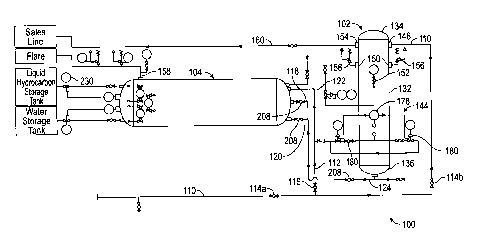
[0010] FIG. 1 is a schematic view of a separator assembly constructed in
accordance with the inventive concepts disclosed herein.
[0011] FIG. 2 is a side elevational view of the separator assembly of
FIG. 1
shown with the piping removed for the sake of clarity.
3
CA 02805161 2013-02-08
[0012] FIG. 3 is a cross-sectional view of a first stage vertical
separator.
[0013] FIG. 4 is a cross-sectional view of the first stage vertical
separator.
[0014] FIG. 5 is a side elevational view of an exemplary embodiment of a
second
stage horizontal separator.
[0015] FIG. 6 is a detail cross-sectional view of a fluid inlet of the
second stage
horizontal separator of FIG. 5.
[0016] FIG. 7A is a perspective view of a weir system of the second stage
horizontal separator.
[0017] FIG. 7B is a perspective view of the weir system of FIG. 7A.
[0018] FIG. 7C is a perspective view of a water chamber of the second
stage
horizontal separator.
[0019] FIG. 7D is a perspective view of the weir system of FIG. 7A
rotated 900
.
DETAILED DESCRIPTION OF EXEMPLARY EMBODIMENTS
[0020] The inventive concepts disclosed herein are generally directed to
a
separator assembly and more particularly, but not by way of limitation, to a
mobile
separator assembly configured to handle large volumes of flowback water and to
carry
out a three-stage separation process of gas, liquid, and solids from flowback
fluids,
without allowing substantial amounts of HAPs or VOCs to be emitted to the
environment.
[0021] Before explaining at least one embodiment of the inventive
concepts
disclosed herein in detail, it is to be understood that the inventive concepts
are not
limited in their application to the details of construction and the
arrangement of the
components or steps or methodologies set forth in the following description or
illustrated
4
CA 02805161 2013-02-08
in the drawings. The inventive concepts disclosed herein are capable of other
embodiments or of being practiced or carried out in various ways. Also, it is
to be
understood that the phraseology and terminology employed herein is for the
purpose of
description only and should not be regarded as limiting the inventive concepts
disclosed
and claimed herein in any way.
[0022] In the following detailed description of embodiments of the
inventive
concepts, numerous specific details are set forth in order to provide a more
thorough
understanding of the inventive concepts. However, it will be apparent to one
of ordinary
skill in the art that the inventive concepts within the disclosure may be
practiced without
these specific details. In other instances, well-known features may not be
described in
detail to avoid unnecessarily complicating the instant disclosure.
[0023] As used herein the notation "a-n" appended to a reference numeral
is
intended as merely convenient shorthand to reference one, or more than one,
and up to
infinity, of the element or feature identified by the respective reference
numeral (e.g.,
134a-n). Similarly, a letter following a reference numeral is intended to
reference an
embodiment of the feature or element that may be similar, but not necessarily
identical,
to a previously described element or feature bearing the same reference
numeral (e.g.,
148, 148a, 148b, etc.). Such shorthand notations are used for purposes of
clarity and
convenience only, and should not be construed to limit the instant inventive
concepts in
any way, unless expressly stated to the contrary.
[0024] As used herein the term "sales gas," and any variations thereof,
is
intended to include the gas, gases, or vapors, obtained from a well, which are
not
necessarily sold directly to consumers, but may be further processed (e.g.,
dehydrated
CA 02805161 2013-02-08
or "sweetened"), used for fuel at the well site, flared or combusted, and
combinations
thereof, for example.
[0025] Further, unless expressly stated to the contrary, "or" refers to
an inclusive
"or" and not to an exclusive "or." For example, a condition A or B is
satisfied by anyone
of the following: A is true (or present) and B is false (or not present), A is
false (or not
present) and B is true (or present), and both A and B are true (or present).
[0026] In addition, use of the "a" or "an" are employed to describe
elements and
components of the embodiments herein. This is done merely for convenience and
to
give a general sense of the inventive concepts. This description should be
read to
include one or at least one and the singular also includes the plural unless
it is obvious
that it is meant otherwise.
[0027] Finally, as used herein any reference to "one embodiment" or "an
embodiment" means that a particular element, feature, structure, or
characteristic
described in connection with the embodiment is included in at least one
embodiment.
The appearances of the phrase "in one embodiment" in various places in the
specification are not necessarily all referring to the same embodiment.
[0028] Referring now to FIGS. 1-2, shown therein is an exemplary
embodiment of
a separator assembly 100 according to the inventive concepts disclosed herein.
The
separator assembly 100 may be referred to as "SA" hereinafter. The SA 100 is
designed
to handle large volumes of flowback water recovered from a well site upon
hydraulic
fracture completion. The SA 100 provides primary stage two-phase separation of
solids,
liquids, and sales gas at the sales gas pressure, and a secondary stage
pressure
reduction to a high-retention capable three-phase separation for condensate
and
6
CA 02805161 2013-02-08
flowback water stabilization and diversion of flash gases to a combustor or a
flare.
Flowback water, now devoid of much of the entrained gases and condensates, may
be
safely stored into storage tanks on site, or may be further processed, or
otherwise
disposed of.
[0029] The SA 100 comprises a first stage vertical separator 102 and a
second
stage horizontal separator 104, and may be designed to be moved from one well
site to
another via a trailer 106. While the SA 100 is shown as being mounted on a
flatbed
trailer 106, it is to be understood that the vertical separator 102 and the
horizontal
separator 104 may be mounted on separate trailers (not shown). Further the SA
100
may be transported with conventional means (e.g., trucks, trailers, etc.) and
may be
permanently or semi-permanently installed at a well site, for example.
Further, the SA
100 may be mounted on a skid (not shown), or a railroad car (not shown), or
may be
loaded onto a truck and moved in variety of ways as will be understood by
persons of
ordinary skill in the art. The SA 100 may also be permanently or semi-
permanently
installed at any suitable location, such as a well site, an offshore rig, or
an oil refinery,
for example. The SA 100 may be disassembled for transport or storage, and may
be
transported and assembled at any desired location, as will be understood by
persons of
ordinary skill in the art having the benefit of the instant disclosure.
[0030] During the flowback stage of the hydraulic fracturing process, the
SA 100
may be implemented to replace a conventional gas-processing unit, by being
fluidly
connected with the well such that wellstream fluids, or flowback fluid exiting
the well,
enter the SA 100. It is to be understood that a SA 100 according to the
inventive
concepts disclosed herein may be implemented during any stage of oil well
drilling, oil
7
CA 02805161 2013-02-08
production, gas well drilling, or gas production, and is particularly suitable
for processing
large volumes of fluid, such as the large volumes of fluid recovered from a
well during
the flowback stage of the hydraulic fracturing process, for example.
[0031] Generally, fluids are introduced into the first stage vertical
separator 102
where the fluids are directed downward towards the bottom of the first stage
vertical
separator 102. The vertical separator 102 may be operated at the sales gas
pressure.
Sand, sediment, and liquids settle to the bottom of the vertical separator
102, while
gases and vapors (i.e., sales gas), including natural gas, VOCs, and HAPs,
rise upward
towards the top of the vertical separator 102. Rising gases are passed from
the first
stage vertical separator in a pressure regulated manner via a gas line. The
liquid level
inside the vertical separator 102 is controlled by, for example, one or more
control
valves, and fluids are passed, in a pressure regulated manner, into the second
stage
horizontal separator 104.
[0032] The horizontal separator 104 is maintained at a suitable pressure
above
atmospheric pressure to prevent excessive flashing off of gases thereby
maintaining
more hydrocarbons in liquid form. Sand/sediment may be periodically blown off
from the
vertical separator 102 into the horizontal separator 104. By passing the
sand/sediment
to the horizontal separator 104, a significant portion of gaseous or liquid
VOCs which
are absorbed by the sand/sediment, or with which the sand/sediment came into
contact,
are removed from the sand/sediment, and captured for disposal.
[0033] Upon entering the horizontal separator 104, the fluids and the
sand/sediment are directed downward towards the bottom of the horizontal
separator
104. Once in the horizontal separator 104, the fluids flow over an internal
weir system
8
CA 02805161 2013-02-08
and the heavier sand/sediments settle on the bottom of the horizontal
separator 104. Oil
and other hydrocarbons are separated from water and stabilized, and flow into
a
separate oil chamber. The water passes to a separate water chamber. Any
remaining
entrained gases, HAPs, or VOCs rise toward the top of the horizontal separator
104 and
are passed to a combustor or flare. The liquid hydrocarbons are passed to a
hydrocarbon storage tank and the water is passed to a water storage tank.
Further, the
sand/sediment, now devoid of much of the gaseous and liquid VOCs it came into
contact or was contaminated with, may be removed from the horizontal separator
104
and disposed of in compliance with any applicable environmental regulations,
for
example.
[0034] The SA 100 includes a wellstream intake conduit 110. The intake
conduit
110 is adapted to be connected to a well via suitable piping (not shown). The
intake
conduit 110 passes the well fluids to the first stage vertical separator 102.
On one
embodiment, the intake conduit 110 is connected to the vertical separator 102
at a
location which about 75% of the height of the vertical separator 102 such that
well
stream fluids enter the vertical separator 102 at about 75% of its height. It
is to be
understood that such arrangement is only exemplary, and the intake conduit 110
may
connect with the vertical separator 102 at any location, such as a top end, a
bottom end,
and along any portion of the sidewall of the vertical separator 102.
[0035] A bypass conduit 112 is in fluid communication with the intake
conduit 110
and with the horizontal separator 104 via a fluid inlet. One or more valves
114 can be
used to control the flow of fluids through the intake conduit 110. For
example, a valve
114a can be operated to place the intake conduit 110 in fluid communication
with a
9
CA 02805161 2013-02-08
wellstream fluids source. Further, the valve 114a can be operated to remove
the intake
conduit 110 from fluid communication with a wellstream fluids source. Further,
a valve
114b may be operated to allow fluids to flow through the intake conduit 110
and into the
vertical separator 102, or may be operated to prevent fluids from entering the
vertical
separator 102 via the intake conduit 110. A valve 116 may be operated to allow
fluids to
flow into the horizontal separator 104 via the bypass conduit 112, or may be
operated to
prevent fluids from flowing into the horizontal separator 104 via the bypass
conduit 112,
for example.
[0036] The horizontal separator 104 is in fluid communication with the
vertical
separator 102 via an upper sand/sediment conduit 118, a lower sand/sediment
conduit
120, and a fluid transfer conduit 122. The upper sand/sediment conduit 118 and
the
lower sand/sediment conduit 120 are in fluid communication with a sand blow-
off
conduit 124.
[0037] Referring now to FIGS. 3-4, the vertical separator 102 may be
implemented as a high-pressure vertical separator 102. The vertical separator
102
comprises a high-pressure vessel 130 having a sidewall 132, a top end 134, and
a
bottom end 136. The high-pressure vessel 130 may be connected to the trailer
106 via
a base flange 138, for example. The vertical separator 102 further comprises
an
impingement plate assembly 140, a mist extractor assembly 142, and a liquid
level
control assembly 144.
[0038] The high-pressure vessel 130 may be made of any suitable material
capable of handling the pressure and abrasion likely to be encountered by the
SA 100.
For example, the high-pressure vessel 130 may be constructed of steel,
stainless steel,
CA 02805161 2013-02-08
aluminum, or other metals, or non-metals, and combinations thereof. In an
exemplary
embodiment, the sidewall 132 of the high-pressure vessel may comprise a 48"
outer
diameter and a 96" height, and may be rated for maximum allowable working
pressure
(MAWP) of about 1440 psig, and a working temperature range from about -12
Fahrenheit to about 200 Fahrenheit. In a non-limiting embodiment, the
vertical
separator 102 may have an estimated liquid handling capacity of 900 barrels a
day with
a 3-5 minute retention time, and a sales gas capacity varying from about 5
million
standard cubic feet per day (MMSCFD) at 250 psig to about 33 MMSCFD at 1400
psig.
The empty weight of the vertical separator 102 may be about 10,650 lbs., for
example.
[0039] The vertical separator 102 has a fluid inlet 146, a fluid outlet
148, one or
more pressure-relief openings 150, an optional pressure gauge 152 (FIG. 1), an
optional cleanout access (not shown), and a gas outlet 154.
[0040] The fluid inlet 146 functions to allow fluids to enter the
vertical separator
102. The fluid inlet 146 may be implemented as a three-inch Schedule Extra
Heavy
coupling, for example, or in any other suitable way, such that the fluid inlet
146 is in fluid
communication with the intake conduit 110, and a substantially fluid-
impermeable
connection is formed between the fluid inlet 146 and the intake conduit 110.
In an
exemplary embodiment, the fluid inlet 146 is desirably positioned at about
three-
quarters (about 75%) of the height of the sidewall 132, such that fluids enter
the vertical
separator 102 at about three-quarters of the height of the sidewall 132. It is
to be
understood, however, that in some embodiments of the instant inventive
concepts the
vertical separator 102 may comprise more than one fluid inlet 146, and the
fluid inlets
11
CA 02805161 2013-02-08
146 may be formed at any height on the sidewall 132, or in the top end 134 or
the
bottom end 136, and combinations thereof, for example.
[0041] The fluid outlet 148 may be implemented as a three-inch Schedule
Extra
Heavy coupling, for example. The fluid outlet 148 is in fluid communication
with the fluid
transfer conduit 122 (FIG. 1). The fluid outlet 148 may be formed at
approximately 30%
of the height of the sidewall 132, such that the level of fluids inside the
vertical separator
102 can be maintained at about 30% of the volume of the vertical separator 102
by the
liquid level control assembly 144, as will be described below, for example. It
is to be
understood that in some exemplary embodiments of the inventive concepts
disclosed
herein, the vertical separator 102 may comprise more than one fluid outlet
148. Further,
the fluid outlet 148 according to the inventive concepts disclosed herein may
be
positioned at any height along the sidewall 132, may be formed into the top
end 134,
the bottom end 136, and combinations thereof, for example.
[0042] The one or more pressure-relief openings 150 may be operatively
coupled
to a pressure-relief valve 156 (FIG. 1), such that excess pressure may be
released by
the pressure-relief valve 156 when a predetermined threshold pressure is
exceeded
inside the vertical separator 102. To avoid releasing VOCs or other
contaminants into
the environment, such excess pressure may be released by allowing fluids or
gases to
escape the vertical separator 102, and enter the horizontal separator 104, for
example.
Alternatively, such excess pressure may be released by allowing fluids to
escape the
vertical separator 102 and enter a combustor/flare line 158, where the fluids
may be
safely disposed of by combusting or flaring, for example.
12
CA 02805161 2013-02-08
[0043] The optional pressure gauge 152 may be connected to the sidewall
132,
and may be in fluid communication with the interior of the high-pressure
vessel 130
such that the pressure gauge 152 may detect the pressure inside the high-
pressure
vessel 130 and display the detected pressure in a form perceivable by a user.
The
optional pressure gauge 152 may display the pressure inside the high-pressure
vessel
130 locally, or may transmit the pressure to a remotely located control panel
or system
(not shown), and combinations thereof, for example.
[0044] The optional cleanout access may be implemented as a four-inch by
eight-
inch schedule extra heavy weld neck, for example. The cleanout access is
desirably
sealed in a fluid-impermeable way during the operation of the SA 100, and may
be used
to permit access, cleaning, or maintenance, of the interior and internal
components of
the vertical separator 102, as will be appreciated by persons of ordinary
skill in the art
having the benefit of the instant disclosure.
[0045] The gas outlet 154 functions to allow sales gas to be removed from
the
vertical separator 102 and conveyed into a gas line 160 (FIG. 1). The gas
outlet 154 is
desirably formed near the top of the sidewall 132, and is in fluid
communication with the
gas line 160.
[0046] The top end 134 may optionally comprise one or more ears (not
referenced) adapted to allow a crane hook or a steel rope to be used to lift
and move
the vertical separator 102, for example. The top end 134 may further comprise
a top
end access 162, which may be implemented as a one-inch coupling, or in any
other
suitable manner, for example.
13
CA 02805161 2013-02-08
[0047] The bottom end 136 desirably comprises a sand blow-off conduit 124
formed therein, such that sand and sediment may be periodically blown off, or
transferred, from the vertical separator 102 into the horizontal separator 104
via the
sand blow-off conduit 124.
[0048] The sand blow-off conduit 124 may be implemented, for example, as
a
three-inch Schedule Extra Heavy pipe, or in any other suitable manner as will
be
understood by persons of ordinary skill in the art. Due to the high pressures
in the well
and in the vertical separator 102, some gaseous or liquid hydrocarbons or VOCs
may
come into contact with the sand/sediment that is carried into the vertical
separator 102
by the flowback fluids. Such sand/sediment may be contaminated with VOCs, and
such
sand/sediments may remain contaminated inside the vertical separator 102, due
to the
high pressure therein, which prevents the VOCs from evaporating. Therefore, if
such
contaminated sand/sediment were to be removed directly from the vertical
separator
102, any VOCs contained therein would be released into the environment. To
avoid
releasing such VOCs into the environment, the contaminated sand/sediment is
transferred from the vertical separator 102, directly into the horizontal
separator 104,
where the contaminating VOCs may evaporate, bubble-off, or otherwise separate
from
the sand/sediment, and may be safely disposed of, such as by flaring, for
example.
Desirably, no contaminated sand/sediment from the vertical separator 102 is
allowed to
come into contact with the environment. Decontaminated sand/sediment is
removed
from the horizontal separator 104 as will be described below.
[0049] The base flange 138 may be implemented as a cylindrical base
flange 138
used to attach the vertical separator 102 to the trailer 106 in a spaced apart
vertical
14
CA 02805161 2013-02-08
orientation, such that the sand blow-off conduit 124 can extend from the
bottom end 136
of the vertical separator 102, for example. The base flange 138 may be
attached to the
vertical separator 102 and to the trailer 106, in any suitable manner, such as
via welds,
bolts, screws, joints, seams, adhesives, and combinations thereof, for
example. The
vertical separator 102 is mounted onto the trailer 106, such that the vertical
separator
102 is substantially vertically oriented, and the bottom end 136 is adjacent
to, or
connected with, the trailer 106. It is to be understood that "substantially
vertically" as
used herein, is intended to mean that the vertical separator 102 is generally
vertical
relative to a generally horizontal top surface of the trailer 106. As will be
understood by
persons of ordinary skill in the art, substantially vertically encompasses
deviations from
a 90 angle between the trailer 106 and the vertical separator 102, due to the
trailer 106
being positioned on uneven surfaces, natural topography variations,
manufacturing
tolerances, etc. Further, in some exemplary embodiments of the instant
inventive
concepts, the vertical separator 102 may be oriented in a variety of angles
relative to
the trailer 106, and such angles may range from 0 -180 . In other exemplary
embodiments, the angle between the vertical separator 102 and the trailer 106
may be
adjustable to ensure a generally vertical orientation of the vertical
separator 102 relative
to a horizontal top surface of the trailer 106 during operation of the SA 100.
[0050]
The impingement plate assembly 140 is desirably at least partially
disposed inside the high-pressure vessel 130, and is shown positioned over the
fluid
inlet 146, such that fluids entering the vertical separator 102 via the fluid
inlet 146
impinge, or otherwise encounter, an impingement plate 166, and are deflected,
or
otherwise directed downward, toward the bottom end 136 of the vertical
separator 102.
CA 02805161 2013-02-08
It is to be understood that in exemplary embodiments comprising more than one
fluid
inlet 146, more than one impingement plate 166 may be implemented, or
alternatively a
single impingement plate 166 may be positioned over two or more fluid inlets
146 to
intercept incoming fluids and direct them downwards into the vertical
separator 102. The
impingement plate 166 may comprise a horizontal portion 168 to prevent
splashing of
liquids upward, and an angled portion 170 to redirect fluids downward toward
the
bottom end 136. The impingement plate 166 may be constructed of any suitable
material, but is desirably constructed from abrasion-resistant and corrosion-
resistant
material, such as steel, titanium, metals, non-metals, and combinations
thereof, for
example. Further, the impingement plate 166 may be uncoated, or may be coated
with
a variety of coatings, such as paints, corrosion-suppressing agents, abrasion-
resistant
coatings, and combinations thereof, for example. The impingement plate 166 may
be
connected to the sidewall 132 in any suitable manner, such as by welds, seams,
rivets,
bolts, brackets, flanges, screws, adhesives, and combinations thereof, for
example. The
design, placement, and implementation of the impingement plate assembly 140
may be
based upon Gas Processing Suppliers Association separator design standards, as
will
be understood by a person of ordinary skill in the art having the benefit of
the instant
disclosure.
[0051]
The mist extractor assembly 142 comprises a mist pad support 172 and a
mist pad 174. The mist pad support 172 is attached to the sidewall 132 and is
desirably
positioned above the impingement plate 166, and below the gas outlet 154. The
mist
pad support 172 may be attached to the sidewall 132 in any suitable manner,
such as
16
CA 02805161 2013-02-08
welds, seams, adhesives, flanges, brackets, bolts, screws, rivets, and
combinations
thereof, for example. The mist pad support 172 functions to support the mist
pad 174.
[0052] The mist pad 174 may be implemented as any conventional mist pad
174,
and functions to absorb any mist, aerosolized liquids, or liquid droplets,
while allowing
gases to pass therethrough, such that gases may enter the gas line 160
substantially
fee of liquids. The design, placement, and implementation of the mist
extractor
assembly 142 may be based upon Gas Processing Suppliers Association separator
design standards, as will be understood by a person of ordinary skill in the
art having
the benefit of the instant disclosure, for example.
[0053] The liquid level control assembly 144 comprises a shroud 176 and a
liquid
level controller 178. The shroud 176 may be implemented as a shroud (e.g., a
baffle),
and may be attached to the sidewall 132 in any suitable manner, such as by
welds,
seams, adhesives, bolts, screws, rivets, and combinations thereof, for
example. The
shroud 176 is desirably implemented such that the shroud 176 is disposed above
the
liquid level controller 178, and substantially prevents fluids directed
downwards by the
impingement plate 166 from directly contacting the liquid level controller
178. The
shroud 176 is shown as an L-shaped shroud 176, but it is to be understood that
the
shroud 176 may comprise and suitable shape capable of substantially preventing
incoming fluids from directly contacting the liquid level controller 178 prior
to reaching
the bottom end 136 of the vertical separator 102, and allowing the sand and
sediment
carried by the fluids to settle at the bottom end 136.
[0054] The liquid level controller 178 (FIG. 1) may be implemented as a
conventional liquid level controller 178, such as a mechanical float, for
example,
17
CA 02805161 2013-02-08
configured to maintain a preset level of liquid (desirably to about thirty
percent of the
volume of the vertical separator 102) into the vertical separator 102, and to
transfer
fluids into the horizontal separator 104 in a pressure-regulated manner. The
transfer of
fluids between the vertical separator 102 and the horizontal separator 104 is
desirably
driven by the pressure differential between the vertical separator 102 and the
horizontal
separator 104, for example. The liquid level controller 178 is in fluid
communication with
the fluid outlet 148. One or more dump valves 180 may be used to transfer
fluids from
the vertical separator 102 to the horizontal separator 104 as will be
described below.
The liquid level controller 178 design, placement, and implementation may be
based
upon Gas Processing Suppliers Association separator design standards, as will
be
understood by a person of ordinary skill in the art having the benefit of the
instant
disclosure, for example.
[0055]
Referring now to FIGS. 5-6, the horizontal separator 104 may be
implemented similarly to the vertical separator 102, and is in fluid
communication with
the vertical separator 102, as will be described herein below. The horizontal
separator
104 comprises a low-pressure vessel 182 having a cylindrical sidewall 184, a
rear end
186, and a front end 188. The horizontal separator 104 further comprises an
impingement plate assembly 190 (FIG. 6), and an internal weir system 192
(FIGS. 7A-
7D) defining a water chamber 194, and an oil chamber 196. In an exemplary
embodiment, the horizontal separator 104 may be implemented as an American
Society
of Mechanical Engineers (ASME) certified horizontal three-stage separator
vessel,
which may have an external diameter of approximately ninety-six inches and may
be
approximately three-hundred inches long. The horizontal separator 104 may be
rated
18
CA 02805161 2013-02-08
for fifty psig MAWP, and may have a working temperature range from about -20
Fahrenheit to 200 Fahrenheit. The horizontal separator 104 may be constructed
of
steel, for example, and may have an exemplary empty weight of approximately
12,000
lbs., and may have an exemplary total liquid handling capability from
approximately
4,500 barrels/day with a retention time of sixty minutes to 9,000 barrels/day
with a
retention time of thirty minutes. Desirably, the horizontal separator 104
design and
implementation may be based upon Gas Processing Suppliers' Association (GPSA)
separator design standards, for example.
[0056] The sidewall 184 may be implemented similarly to the sidewall 132
and
may comprise one or more cleanout access 198, and a vapor/gas outlet 200.
[0057] The cleanout access 198 may be implemented as a four-inch by eight-
inch
schedule extra heavy weld neck, for example. The cleanout access 198 is
desirably
sealed in a fluid-impermeable way during the operation of the SA 100, and may
be used
to permit access, cleaning, and maintenance of the interior of the horizontal
separator
104, as will be appreciated by persons of ordinary skill in the art.
[0058] The vapor/gas outlet 200 may be formed in a top portion of the
sidewall
184, and may be in fluid communication with the combustor/flare line 158. The
vapor/gas outlet 200 functions to remove any vapors and gases from the
horizontal
separator 104. The vapor/gas outlet 200 may be implemented as a four-inch
raised-face
slip on flange connected to the sidewall 184 in a fluid-impermeable manner,
for
example, or in any other suitable manner. The vapor/gas outlet 200 functions
to allow
and gases or vapors released inside the horizontal separator 104 to be safely
disposed
of, such as by combustion, or flaring, for example.
19
CA 02805161 2013-02-08
[0059] The rear end 186 may be implemented similarly to the bottom end
136
and may comprise a fluid inlet 202, a lower sand/sediment inlet 204, and an
upper
sand/sediment inlet 206. The rear end 186 is desirably connected to the
sidewall 184 in
a fluid-impermeable manner, such as by welds, bolts, screws, seams, joints,
and
combinations thereof, for example. It is to be understood that in some
embodiments, the
rear end 186, and the sidewall 184 may be formed as a unitary body.
[0060] The fluid inlet 202 may be implemented as a three-inch coupling,
for
example, or in any other suitable manner. The fluid inlet 202 is in fluid
communication
with the fluid outlet 148 of the vertical separator 102 via the fluid transfer
conduit 122,
and functions the allow fluids to be transferred from the vertical separator
102 into the
horizontal separator 104, for example via one or more dump valves 180.
[0061] The lower sand/sediment inlet 204 and the upper sand/sediment
inlet 206
are vertically offset and are in fluid communication with the sand blow-off
conduit 124.
The lower sand/sediment inlet 204 and the upper sand/sediment inlet 206
function to
allow contaminated sand/sediment to be transferred from the vertical separator
102 into
the horizontal separator 104, as will be described below. One or more valves
208, such
as threaded ball valves, for example, may be used to selectively allow
sand/sediment to
enter the horizontal separator 104. In a non-limiting embodiment,
sand/sediment may
be initially transferred into the horizontal separator 104 via the lower
sand/sediment inlet
204, and when a predetermined amount of sand/sediment has been transferred in
this
manner, further sand/sediment may be transferred via the upper sand/sediment
inlet
206.
CA 02805161 2013-02-08
[0062] The impingement plate assembly 190 (FIG. 6) comprises an
impingement
plate 210 having a horizontal portion 212 and a vertical portion 214. The
impingement
plate 210 is desirably positioned over the fluid inlet 202, and over the lower
sand/sediment inlet 204 and the upper sand/sediment inlet 206, such that the
impingement plate 210 intercepts any incoming fluids and any incoming
sand/sediment
and direct such incoming fluids and sand/sediment downward toward the bottom
of the
horizontal separator 104.
[0063] The front end 188 may be implemented similarly to the top end 134
and
may comprise a water outlet 216, and an oil outlet 218. The front end 188 is
desirably
connected to the sidewall 184 in a fluid-impermeable manner.
[0064] The water outlet 216 is in fluid communication with the water
chamber
194, and functions to allow water to be removed from the horizontal separator
104. The
water outlet 216 may be implemented as a three-inch coupling, for example, or
in any
other suitable manner.
[0065] The oil outlet 218 is in fluid communication with the oil chamber
196, and
functions to allow oil to be removed from the horizontal separator 104. The
oil outlet 218
may be implemented as a three-inch coupling, for example, or in any other
suitable
manner.
[0066] Referring now to FIGS. 7A-7D, the internal weir system 192
comprises
one or more weirs 220, positioned such that the weirs 220 define the water
chamber
194 and the oil chamber 196. As can be seen in FIG. 7A, a weir 220a defining
the oil
chamber 196 has a height over which oil can flow into the oil chamber 196. The
weir
220b defining the water chamber 194 has a bottom opening 222, which allows
water to
21
CA 02805161 2013-02-08
flow into the water chamber 194. The weirs 220 may be implemented as any
conventional weirs 220, as will be understood by a person of ordinary skill in
the art
having the benefit of the instant disclosure. The water chamber 194 and the
oil chamber
196 are desirably mechanically level controlled and in fluid communication
with the
water outlet 216 and the oil outlet 218, respectively.
[0067] The weirs 220 may be connected to the sidewall 184 and the front
end
188, so that the weirs 220 cooperate with the sidewall 184 and with the front
end 188 to
define the water chamber 194 and the oil chamber 196 as shown in FIGS. 7A and
7D,
in some exemplary embodiments.
[0068] The horizontal separator 104 may be mounted onto the trailer 106
via one
or more optional bases 224 (FIG. 5), such that the horizontal separator 104 is
securely
attached to the trailer 106. It is to be understood that while such bases 224
are shown
as substantially C-shaped bases 224, the bases 224 may be any conventional
bases
224. Further, in some exemplary embodiments, the bases 224 may be omitted, or
may
be formed as a unitary body with the trailer 106 or with the horizontal
separator 104, as
will be understood by persons of ordinary skill in the art.
[0069] In operation, the SA 100 is used as follows. Flowback fluid from
the
wellhead is introduced into the first stage vertical separator 102 via the
intake conduit
110. The incoming fluid encounters the impingement plate 166, which causes
heavier
solids and liquids to settle to the bottom of the vertical separator 102. The
gas or vapor
components of the wellstream fluids migrate upwardly through the mist
extractor
assembly 142, and pass from the vertical separator 102 to the sales gas line
160.
22
CA 02805161 2013-02-08
[0070]
Collected solids may be manually removed from the vertical separator 102
at the bottom of the vertical separator 102, such as by periodically operating
one or
more valves 208, which cause a solids stream to be blown into the horizontal
separator
104 via the upper sand/sediment conduit 118 and the lower sand/sediment
conduit 120.
The lower sand/sediment conduit 120 transfers the solids stream into the
horizontal
separator 104 at a first height of the rear end 186, and the upper
sand/sediment conduit
118 transfers sand and sediment into the horizontal separator 104 at a second
height or
the rear end 186, which is greater than the first height, for example. The
sand and
sediment may be transferred into the horizontal separator 104 via the lower
sand/sediment conduit 120 by operating the valve 208, until a layer of
sand/sediment
builds up in the horizontal separator 104 to the first height. Then,
sand/sediment may
continue to be transferred into the horizontal separator 104 via the upper
sand/sediment
conduit 118 by the closing the valve 208 and the opening a valve 208, for
example. As
will be understood, valves 208 may be operated to allow sand/sediment to be
transferred into the horizontal separator 104 via the sand/sediment lower
conduit 120
and the upper sand/sediment conduit 118, one at a time in any order, or via
both the
upper sand/sediment conduit 118 and the lower sand/sediment conduit 120
simultaneously. Further, in some embodiments, only one sand/sediment conduit
118 or
120, or more than two sand/sediment conduits 118 or 120 may be used to
transfer
sand/sediment from the vertical separator 102 to the horizontal separator 104.
Desirably, no VOCs or HAPs are allowed to escape the SA 100 during the
transfer of
sand/sediment from the vertical separator 102 to the horizontal separator 104.
The
23
CA 02805161 2013-02-08
sand/sediment may be periodically removed from the horizontal separator 104
via the
cleanout access 198, for example.
[0071] The liquid stream is level controlled in the vertical separator
102 via the
liquid level controller 178, and flows through the selective operation of one
or more
dump valves 180 into the horizontal separator 104 for further separation.
[0072] The horizontal separator 104 is maintained at a lower pressure and
serves
as the condensate and water stabilization vessel. Inlet liquids undergo the
Joules-
Thompson effect through the first separator dumps, and encounter the
impingement
plate assembly 190 upon entering the horizontal separator 104 via the fluid
inlet 202.
The large size of the horizontal separator 104 provides the necessary
retention times for
proper disengagement of gas entrained in the liquid stream. The horizontal
separator
104 liquid retention volume also provides retention period for the
gravitational/settling
separation of condensate/oil from the flowback liquids. The water stream
collected in
the water chamber is passed to the water storage tank. Condensate enters a
separate
oil chamber 196 after spilling over the internal weir system 192, and is
mechanically
level controlled through its own dump valve 230 to the liquid hydrocarbon
storage tank.
Entrained vapor released in the horizontal separator 104 is passed to the
combustor or
flare.
[0073] The bypass conduit 112 may be used to bypass the vertical
separator 102
and to direct the fluids coming from the well directly into the horizontal
separator 104
such as by opening the valve 116. The bypass conduit 112 may be implemented to
avoid the release of VOCs into the environment, such as during emergencies,
excess
24
'
CA 02805161 2013-02-08
pressures in the well, pressure-leaks, pressure-losses, or other malfunctions
in the
vertical separator 102, for example.
[0074]
From the above description, it is clear that the inventive concepts
disclosed herein are adapted to carry out the objects and to attain the
advantages
mentioned herein as well as those inherent in the inventive concepts disclosed
herein.
While presently preferred embodiments of the inventive concepts disclosed
herein have
been described for purposes of this disclosure, it will be understood that
numerous
changes may be made which will readily suggest themselves to those skilled in
the art
and which are accomplished within the scope of the inventive concepts
disclosed herein
and defined by the appended claims.