Note: Descriptions are shown in the official language in which they were submitted.
CA 02805248 2013-01-11
1
DESCRIPTION
Title: IMAGE ENCODING METHOD AND IMAGE DECODING METHOD
Field
Embodiments of the present invention relate to
orthogonal transformation and inverse orthogonal
transformation in encoding and decoding of videos.
Background
In recent years, an image coding method with
significantly improved coding efficiency has been
jointly recommended by ITU-T and ISO/IEC as ITU-T REC.
H. 264 and ISO/IEC 14496-10 (hereinafter referred as
"H. 264"). H. 264 carries out discrete cosine
transformation (DCT) and inverse discrete cosine
transformation (IDCT) as orthogonal transformation and
inverse orthogonal transformation on prediction errors
in a target pixel block regardless of a prediction
scheme applied to the target pixel block.
Extended H. 264 is expected to carry out
orthogonal transformation and inverse orthogonal
transformation using individual transform bases for the
respective nine types of prediction modes specified for
intra-picture prediction (intra-prediction), thus
improving the coding efficiency.
CA 02805248 2015-03-30
2
Citation List
Non Patent Literature
Non patent literature 1: M. Karczewicz, "Improved
intra coding", ITU-T SG16/Q. 6, VCEG Document, VCEG-
AF15, April 2007.
Summary
However, it is difficult, in connection with
implementation, to carry out orthogonal transformation
and inverse orthogonal transformation using individual
transform bases for the respective plural types of
prediction modes. For example, hardware implementation
requires not only dedicated hardware for DCT and IDCT
required for H. 264 but also dedicated hardware for
individual orthogonal transformations and inverse
orthogonal transformations for the respective plural
types of prediction directions. The addition of the
dedicated hardware increases the scale of relevant
circuits.
Software implementation enables not only DOT
matrices but also individual transform matrices for the
respective types of prediction directions to be loaded
from a memory as appropriate and held in a cache memory
as appropriate. In this case, the desired orthogonal
transformation and inverse orthogonal transformation
can be implemented by a general-purpose multiplier.
However, disadvantageously, costs increase as a result
=
CA 02805248 2015-03-30
3
of an increase in memory bandwidth or in cache memory
size.
Thus, an object of embodiments is to provide
orthogonal transformation and inverse orthogonal
transformation which enable the coding efficiency to be
improved.
According to an aspect an image encoding method
includes predicting a prediction error of a target
image to be encoded based on an intra-prediction mode.
The method includes setting a combination of a vertical
transform matrix and a horizontal transform matrix
corresponding to the target image based on a
predetermined relation. The combination includes any
of a plurality of transform matrices including a first
transform matrix and a second transform matrix which
increases a coefficient density compared to the first
transform matrix if a one-dimensional orthogonal
transformation in a direction orthogonal to a line of a
group of reference pixels on at least one line is
performed on the prediction error in the intra-
prediction mode in which the group of reference pixels
is referenced to generate an intra-prediction image.
The method includes transforming the prediction error
using the combination of the vertical transform matrix
and the horizontal transform matrix, to obtain
transform coefficients. The method includes encoding
CA 02805248 2013-01-11
4
the transform coefficients and information indicating
the intra-prediction mode for the target image.
According to another aspect, an image decoding
method includes decoding transform coefficients for a
target image to be decoded and information indicating
an intra-prediction mode for the target image. The
method includes setting a combination of a vertical
inverse transform matrix and a horizontal inverse
transform matrix corresponding to the target image
based on a predetermined relation. The combination
includes any of a plurality of transposed matrices of a
plurality of transform matrices including a first
transform matrix and a second transform matrix which
increases a coefficient density compared to the first
transform matrix if a one-dimensional orthogonal
transformation in a direction orthogonal to a line of a
group of reference pixels on at least one line is
performed on the prediction error in the intra-
prediction mode in which the group of reference pixels
is referenced to generate an intra-prediction image.
The method includes inversely transforming the
transform coefficients using the combination of the
vertical inverse transform matrix and the horizontal
inverse transform matrix, to obtain a prediction error.
The method includes generating a decoded image based on
the prediction error.
CA 02805248 2015-03-30
=
4a
According to a further aspect there is provided
an image encoding method comprising:
predicting a prediction error of a target image
to be encoded based on an intra-prediction mode;
setting both of a vertical transform matrix and a
horizontal transform matrix for the target image to a
first transform matrix or a second transform matrix
based on a predetermined relation;
transforming the prediction error using the first
transform matrix as both of the vertical transform
matrix and the horizontal transform matrix to obtain
first transform coefficients when the first transform
matrix is set for both of the vertical transform
matrix and the horizontal transform matrix;
transforming the prediction error using the
second transform matrix as both of the vertical
transform matrix and the horizontal transform matrix
to obtain second transform coefficients when the
second transform matrix is set for both of the
vertical transform matrix and the horizontal transform
matrix; and
encoding the first or second transform
coefficients and information indicating the intra-
prediction mode for the target image.
CA 02805248 2015-03-30
4b
According to a further aspect there is provided
an image decoding method comprising:
decoding transform coefficients for a target
image to be decoded and information indicating an
intra-prediction mode for the target image;
setting both of a vertical inverse transform
matrix and a horizontal inverse transform matrix for
the target image to a first transform matrix or a
second transform matrix based on a predetermined
relation;
inversely transforming the transform coefficients
using the first transform matrix as both of the
vertical inverse transform matrix and the horizontal
inverse transform matrix to obtain a first prediction
error when the first transform matrix is set for both
of the vertical inverse transform matrix and the
horizontal inverse transform matrix;
inversely transforming the transform coefficients
using the second transform matrix as both of the
vertical inverse transform matrix and the horizontal
inverse transform matrix to obtain a second prediction
error when the second transform matrix is set for both
of the vertical inverse transform matrix and the
horizontal inverse transform matrix; and
generating a decoded image based on the first or
second prediction error.
CA 02805248 2013-01-11
Brief Description of the Drawings
FIG. 1 is a block diagram illustrating an image
encoding apparatus according to a first embodiment.
FIG. 2 is a block diagram illustrating an
5 orthogonal transformation unit according to the first
embodiment.
FIG. 3 is a block diagram illustrating an inverse
orthogonal transformation unit according to the first
embodiment.
FIG. 4A is a table illustrating the correspondence
between prediction modes and a vertical transform index
and a horizontal transform index according to the first
embodiment.
FIG. 4B is a table illustrating the correspondence
between the vertical transform index and 1D transform
matrices according to the first embodiment.
FIG. 4C is a table illustrating the correspondence
between the horizontal transform index and 1D transform
matrices according to the first embodiment.
FIG. 4D is a table illustrating the correspondence
between a transform index and the vertical transform
index and the horizontal transform index according to
the first embodiment.
FIG. 4E is a table obtained by integrating FIG. 4A
with FIG. 4D.
FIG. 5A is a block diagram illustrating a
coefficient order control unit according to the first
CA 02805248 2013-01-11
6
embodiment.
FIG. 5B is a block diagram illustrating the
coefficient order control unit according to the first
embodiment.
FIG. 6A is a diagram illustrating the order of
predictive coding of a pixel block.
FIG. 6B is a diagram illustrating an example of a
pixel block size.
FIG. 6C is a diagram illustrating another example
of the pixel block size.
FIG. 6D is a diagram illustrating another example
of the pixel block size.
FIG. 7A is a diagram illustrating an intra-
prediction mode.
FIG. 7B is a diagram illustrating the arrangement
relation between prediction target pixels and reference
pixels.
FIG. 7C is a diagram illustrating an intra-
prediction mode 1.
FIG. 7D is a diagram illustrating an intra-
prediction mode 4.
FIG. 8A is a diagram illustrating a zigzag scan.
FIG. 83 is a diagram illustrating the zigzag scan.
FIG. 8C is a table showing a 2D-1D transformation
utilizing the zigzag scan.
FIG. 9 is a table illustrating individual 2D-1D
transformations for the respective prediction modes.
CA 02805248 2013-01-11
7
FIG. 10A is a flowchart illustrating processing
carried out on a coding target block by the image
encoding apparatus in FIG. 1.
FIG. 10B is a flowchart illustrating the
processing carried out on the coding target block by
the image encoding apparatus in FIG. 1.
FIG. 11 is a diagram illustrating a syntax
structure.
FIG. 12 is a diagram illustrating slice header
syntax.
FIG. 13 is a diagram illustrating coding tree unit
syntax.
FIG. 14 is a diagram illustrating transform unit
syntax.
FIG. 15 is a block diagram illustrating an
orthogonal transformation unit which carries out
orthogonal transformation on each of nine types of
prediction directions using a particular transform
basis.
FIG. 16 is a block diagram illustrating an
orthogonal transformation unit according to a second
embodiment.
FIG. 17 is a block diagram illustrating an inverse
orthogonal transformation unit according to the second
embodiment.
FIG. 18A is a table illustrating the
correspondence between the prediction modes and the
CA 02805248 2013-01-11
8
vertical transform index and the horizontal transform
index according to the second embodiment.
FIG. 18B is a table illustrating the
correspondence between the vertical transform index and
1D transform matrices according to the second
embodiment.
FIG. 18C is a table illustrating the
correspondence between the horizontal transform index
and 1D transform matrices according to the second
embodiment.
FIG. 18D is a table illustrating the
correspondence between the transform index and the
vertical transform index and the horizontal transform
index according to the second embodiment.
FIG. 18E is a table obtained by integrating
FIG. 18A with FIG. 18D.
FIG. 19 is a block diagram illustrating an
orthogonal transformation unit according to a third
embodiment.
FIG. 20 is a block diagram illustrating an inverse
orthogonal transformation unit according to the third
embodiment.
FIG. 21A is a table illustrating the
correspondence between the prediction modes and the
vertical transform index and the horizontal transform
index according to the third embodiment.
FIG. 21B is a table illustrating the
CA 02805248 2013-01-11
9
correspondence between the vertical transform index and
1D transform matrices according to the third
embodiment.
FIG. 21C is a table illustrating the
correspondence between the horizontal transform index
and 1D transform matrices according to the third
embodiment.
FIG. 21D is a table illustrating the
correspondence between the transform index and the
vertical transform index and the horizontal transform
index according to the third embodiment.
FIG. 21E is a table obtained by integrating
FIG. 21A with FIG. 21D.
FIG. 22 is a block diagram illustrating an image
decoding apparatus according to a fourth embodiment.
FIG. 23A is a block diagram illustrating a
coefficient order control unit according to the fourth
embodiment.
FIG. 235 is a block diagram illustrating a
coefficient order control unit according to the fourth
embodiment.
Description of Embodiments
Embodiments will be described below with reference
to the drawings. In the description below, the term
"image" may be replaced with the term "image signal",
"image data", or the like as appropriate.
CA 02805248 2013-01-11
(First Embodiment)
A first embodiment relates to an image encoding
apparatus. An image decoding apparatus corresponding
to the image encoding apparatus according to the
5 present embodiment will be described in a fourth
embodiment. The image encoding apparatus can be
implemented by hardware such as LSI (Large-Scale
Integration) chips, DSPs (Digital Signal Processors),
FPGAs (Field Programmable Gate Arrays), and the like.
10 Furthermore, the image encoding apparatus can also be
implemented by allowing a computer to execute an image
encoding program.
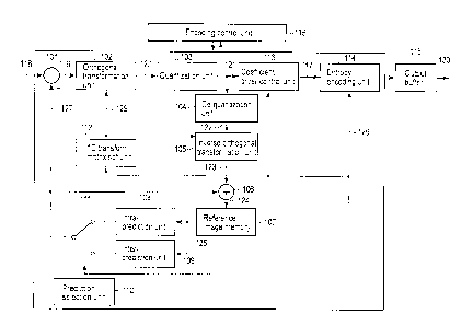
As shown in FIG. 1, the image encoding apparatus
according to the present embodiment includes a
subtraction unit 101, an orthogonal transformation unit
102, a quantization unit 103, a de-quantization unit
104, an inverse orthogonal transformation unit 105, an
addition unit 106, a reference image memory 107, an
intra-prediction unit 108, an inter-prediction unit
109, a prediction selection unit 110, a prediction
selection switch 111, a 1D (one-dimensional)
transformation matrix set unit 112, a coefficient order
control unit 113, an entropy encoding unit 114, an
output buffer 115, and an encoding control unit 116.
The image encoding apparatus in FIG. 1 divides
each of the frame or fields forming an input image 118
into a plurality of pixel blocks, carries out
CA 02805248 2013-01-11
11
predictive coding on the pixel blocks resulting from
the division, and outputs encoded data 130. For
simplification, predictive coding is hereinafter
assumed to be carried out on a pixel block from upper
left to lower right as shown in FIG. 6A. FIG. 6A shows
a coding target frame f in which an encoded pixel
blocks p are positioned to the left of and above a
coding target pixel block c.
Here, the pixel block refers to, for example, a
coding tree unit, a macro block, a sub-block, or a
pixel. The pixel block is hereinafter basically used
to mean a coding tree unit but may be interpreted to
have another meaning as appropriate. The coding tree
unit is typically, for example, a 16 x 16 pixel block
shown in FIG. 6B but may be a 32 x 32 pixel block shown
in FIG. 6C, a 64 x 64 pixel block shown in FIG. 6D, or
an 8 x 8 pixel block or a 4 x 4 pixel block not shown
in the drawings. The coding tree unit need not
necessarily be square. A coding target block or coding
tree unit in the input image 118 is hereinafter
sometimes referred to as a "prediction target block".
Furthermore, the coding unit is not limited to the
pixel block such as the coding tree unit but may be a
frame, a field, or a combination thereof.
The image encoding apparatus in FIG. 1 carries out
intra-prediction (also referred to as intra-frame,
intra-frame prediction, or the like) or
CA 02805248 2013-01-11
12
inter-prediction (also referred to as inter-picture
prediction, inter-frame prediction, or the like) to
generate a predicted image 127. The image encoding
apparatus orthogonally transforms and quantizes a
prediction error 119 between the pixel block (input
image 118) and the predicted image 127. The image
encoding apparatus then carries out entropy encoding on
the transformed and quantized prediction error to
generate and output encoded data 130.
The image encoding apparatus in FIG. 1 carries out
encoding by selective application of a plurality of
prediction modes involving different block sizes and
different methods for generating the predicted image
127. The method for generating the predicted image 127
is roughly classified into two types: intra-prediction
which carries out prediction within the coding target
frame and inter-prediction which carries out prediction
using one or more reference frames temporally different
from one another. In the present embodiment,
orthogonal transformation and inverse orthogonal
transformation carried out to generate a predicted
image using intra-prediction will be described in
detail.
Components of the image encoding apparatus in
FIG. 1 will be described below.
The subtractor 101 subtracts the corresponding
predicted image 127 from the coding target block in the
CA 02805248 2013-01-11
13
input image 118 to obtain the prediction error 119.
The subtractor 101 inputs the prediction error 119 to
the orthogonal transformation unit 102.
The orthogonal transformation unit 102
orthogonally transforms the prediction error 119 from
the subtractor 101 to obtain transform coefficients
120. The orthogonal transformation unit 102 will be
described below in detail. The orthogonal
transformation unit 102 inputs the transform
coefficients 120 to the quantization unit 103.
The quantization unit 103 quantizes the transform
coefficients from the orthogonal transformation unit
102 to obtain quantized transform coefficients 121.
Specifically, the quantization unit 103 carries out
quantization in accordance with quantization
information such as a quantization parameter and a
quantization matrix which is specified by the encoding
control unit 116. The quantization parameter is
indicative of the resolution of the quantization. The
quantization matrix is used to weight the resolution of
the quantization for each component of the transform
coefficients. The quantization unit 103 inputs the
quantized transform coefficients 121 to the coefficient
order control unit 113 and the de-quantization unit
104.
The coefficient order control unit 113 transforms
the quantized transform coefficients 121 which are a
CA 02805248 2013-01-11
14
two-dimensional (2D) expression into a quantized
transform coefficient sequence 117 which is a one-
dimensional (1D) expression. The coefficient order
control unit 113 then inputs the quantized transform
coefficient sequence 117 to the entropy encoding unit
114. The coefficient control unit 113 will be
described below in detail.
The entropy encoding unit 114 carries out entropy
encoding (for example, Huffman encoding or arithmetic
encoding) on various coding parameters such as the
quantized transform coefficient sequence 117 from the
coefficient control unit 113, the prediction
information 126 from the prediction selection unit 110,
and the quantization information which are specified by
the encoding control unit 116. The coding parameters
are required for decoding and include the prediction
information 126, information on the transform
coefficients, and information on the quantization. The
coding parameters are held in an internal memory (not
shown in the drawings) in the encoding control unit
116. When a prediction target block is encoded, the
coding parameters for the already coded adjacent pixel
block can be used. For example, H. 264 intra-
prediction enables a predicted value for the prediction
mode of the prediction target block to be derived from
the prediction mode information on the coded adjacent
block.
CA 02805248 2013-01-11
The encoded data generated by the entropy encoding
unit 114 is, for example, multiplexed and then
temporarily accumulated in the output buffer 115. The
data is then output as the encoded data 130 in
5 accordance with an appropriate output timing managed by
the encoding control unit 116. The encoded data 130 is
output to, for example, an accumulation system
(accumulation medium) or a transmission system
(communication line) which is not shown in the
10 drawings.
The de-quantization unit 104 de-quantizes the
quantized transform coefficients 121 from the
quantization unit 103 to obtain a restored transform
coefficients 122. Specifically, the de-quantization
15 unit 104 carries out de-quantization in accordance with
the quantization information used in the quantization
unit 103. The quantization information used in the
quantization unit 103 is loaded from the internal
memory in the encoding control unit 116. The de-
quantization unit 104 inputs the restored transform
coefficients 122 to the inverse orthogonal
transformation unit 105.
The inverse orthogonal transformation unit 105
carries out an inverse orthogonal transformation
corresponding to the orthogonal transformation
performed by the orthogonal transformation unit 102 on
the restored transform coefficients 122 from the
CA 02805248 2013-01-11
16
de-quantization unit 104 to obtain a restored
prediction error 123. The inverse orthogonal
transformation unit 105 will be described below in
detail. The inverse orthogonal transformation unit 105
inputs the restored prediction error 123 to the
addition unit 106.
The addition unit 106 adds the restored prediction
error 123 and the corresponding predicted image 127
together to generate a local decoded image 124. The
local decoded image 124 is saved to the reference image
memory 107. The local decoded image 124 saved to the
reference image memory 107 is referenced by the intra-
prediction unit 108 and the inter-prediction unit 109
as a reference image 125 as necessary.
The intra-prediction unit 108 carries out intra-
prediction utilizing the reference image 125 saved to
the reference image memory 107. For example, H. 264
utilizes the coded reference pixel value for the block
adjacent to the prediction target bock to compensate
for pixels (copy or interpolate pixels) along a
prediction direction such as the vertical direction or
the horizontal direction to generate an intra-predicted
image. FIG. 7A shows prediction directions for the
intra-prediction according to H. 264. Furthermore,
FIG. 7B shows the arrangement relation between
reference pixels and coding target pixels according to
H. 264. FIG. 7C shows a method for generating a
CA 02805248 2013-01-11
17
predicted image in a mode 1 (horizontal prediction).
FIG. 7D shows a method for generating a predicted image
in a mode 4 (diagonal down-right prediction;
Intra NxN Diagonal Down Right in FIG. 4A).
_ _
The intra-prediction unit 108 may interpolate
pixel values using a predetermined interpolation method
and then copy the interpolated pixel values in a
predetermined prediction direction. The prediction
directions for the intra-prediction according to H. 264
are illustrated, but any number of prediction modes
such as 17 or 33 types of prediction modes are made
available by specifying a more detailed classification
of prediction directions. For example, H. 264 defines
prediction angles at intervals of 22.5 degrees, but 17
types of prediction modes including DC prediction are
made available by specifying prediction angles at
intervals of 11.25 degrees. Furthermore, 33 types of
prediction modes including DC prediction are made
available by specifying prediction angles at intervals
of 5.625 degrees. Alternatively, instead of being
arranged at equal intervals, the angles of the
prediction directions may each be expressed by a
straight line which joins a first reference point to a
second reference point obtained by moving the first
reference point in the horizontal direction and in the
vertical direction. As described above, the number of
prediction modes can be easily increased, and the
CA 02805248 2013-01-11
18
present embodiment is applicable regardless of the
number of prediction modes.
The inter-prediction unit 109 carries out inter-
prediction utilizing the reference image 125 saved to
the reference image memory 107. Specifically, the
inter-prediction unit 109 carries out a block matching
process between the prediction target block and the
reference image 125 to derive the amount of deviation
in motion (motion vector). The inter-prediction unit
109 carries out an interpolation process (motion
compensation) based on the motion vector to generate an
inter-predicted image. H. 264 enables the
interpolation process to be achieved to an accuracy of
a 1/4 pixel. The derived motion vector is subjected to
entropy encoding as a part of the prediction
information 126.
The selection switch 111 selects an output end of
the intra-prediction unit 108 or an output end of the
inter-prediction unit 109 in accordance with the
prediction information 126 from the prediction
selection unit 110. The selection switch 111 then
inputs an intra-predicted image or an inter-predicted
image to the subtraction unit 101 and the addition unit
106 as the predicted image 127. If the prediction
information 126 is indicative of intra-prediction, the
selection switch 110 acquires the intra-predicted image
from the intra-prediction unit 108 as a predicted image
CA 02805248 2013-01-11
19
127. On the other hand, if the prediction information
126 is indicative of inter-prediction, the selection
switch 110 acquires the inter-predicted image from the
inter-prediction unit 109 as a predicted image 127.
The prediction selection unit 110 has a function
to set the prediction information 126 in accordance
with the prediction mode controlled by the encoding
control unit 116. As described above, the intra-
prediction or the inter-prediction can be selected for
generation of the predicted image 127. Moreover, a
plurality of modes can further be selected for each of
the intra-prediction or the inter-prediction. The
encoding control unit 116 determines one of the
plurality of prediction modes for the intra-prediction
and the inter-prediction to be the optimum prediction
mode. The prediction selection unit 110 sets the
prediction information 126 according to the determined
optimum prediction mode.
For example, in connection with the intra-
prediction, the prediction mode information from the
encoding control unit 116 is specified in the intra-
prediction unit 108. In accordance with the prediction
mode information, the intra-prediction unit 108
generates the predicted image 127. The encoding
control unit 116 may specify a plurality of pieces of
prediction mode information in order of increasing
number of the prediction mode or decreasing number of
CA 02805248 2013-01-11
the prediction mode. Furthermore, the encoding control
unit 116 may limit the prediction mode in accordance
with the characteristics of the input image. The
encoding control unit 116 need not specify all the
5 prediction modes but may specify at least one piece of
prediction mode information for the coding target
block.
For example, the encoding control unit 116
determines the optimum prediction mode using a cost
10 function shown in:
K =SAD+Xx OH (1)
In Expression (1), OH denotes the amount of code
for the prediction information 126 (for example, motion
15 vector information and prediction block size
information), and SAD denotes the sum of absolute
difference between the prediction target block and the
predicted image 127 (that is, the accumulated sum of
the absolute values of the prediction error 119).
20 Furthermore, X, denotes a Lagrange multiplier determined
based on the value of the quantization information
(quantization parameter), and K denotes a coding cost.
If Expression (1) is used, the prediction mode which
minimizes the coding cost K is determined to be optimum
in terms of the amount of generated code and prediction
errors. As a modification of Expression (1), the
coding cost may be evaluated only from the OH or the
SAD or by utilizing a value obtained by carrying out an
CA 02805248 2013-01-11
21
Hadamard transformation on the SAD or a value
approximate thereto.
Furthermore, the optimum prediction mode can be
determined using a provisionally encoding unit (not
shown in the drawings). For example, the encoding
control unit 116 determines the optimum prediction mode
using a cost function shown in:
J=D+AxR (2)
In Expression (2), D denotes the sum of square
differences (that is, coding distortion) between the
prediction target block and a local decoded image, R
denotes the amount of code estimated by provisionally
encoding the predicted error between the prediction
target block and the predicted image 127 for the
prediction mode, and J denotes the coding cost. To
derive the coding cost in Expression (2), a
provisionally encoding process and a local decoding
process need to be carried out in each prediction mode.
This increases the scale of relevant circuits or the
amount of calculation. On the other hand, the coding
cost J is derived based on a more accurate coding
distortion and a more accurate amount of code.
Therefore, the optimum prediction mode is accurately
determined to allow a high coding efficiency to be
easily maintained. As a modification of Expression
(2), the coding cost may be evaluated only from the R
or the D or by utilizing a value approximate to the R
CA 02805248 2013-01-11
22
or the D. Furthermore, the encoding control unit 116
may, in advance, narrow down the number of candidates
for the prediction mode one of which is determined
using Expression (1) or Expression (2), based on
information pre-obtained for the prediction target
block (prediction modes for the surrounding pixel
blocks, the results of image analysis, and the like).
The encoding control unit 116 controls the
components of the image encoding apparatus in FIG. 1.
Specifically, the encoding control unit 116 performs
various control operations for an encoding process
including the above-described operations.
The 1D transform matrix set unit 112 generates 1D
transform matrix set information 129 based on the
prediction mode information included in the prediction
information 126 from the prediction selection unit 110.
The 1D transform matrix set unit 112 then inputs the 1D
transform matrix set information 129 to the orthogonal
transformation unit 102 and the inverse orthogonal
transformation unit 105. The 1D transform matrix set
information 129 will be described below in detail.
The orthogonal transformation unit 102 according
to the present embodiment will be described below in
detail with reference to FIG. 2.
The orthogonal transformation unit 102 includes a
selection switch 201, a vertical transformation unit
202, a transposition unit 203, a selection switch 204,
CA 02805248 2013-01-11
23
and a horizontal transformation unit 205. The vertical
transformation unit 202 includes a 1D orthogonal
transformation unit A 206 and a 1D orthogonal
transformation unit B 207. The horizontal
transformation unit 205 includes a 1D orthogonal
transformation unit A 208 and a 1D orthogonal
transformation unit B 209. The order of the vertical
transformation unit 202 and the horizontal
transformation unit 205 is illustrative and may be
reversed.
The 1D orthogonal transformation unit A 206 and
the 1D orthogonal transformation unit A 208 have common
functions in that both units multiply an input matrix
by a 1D transform matriX A. The 1D orthogonal
transformation unit B 207 and the 1D orthogonal
transformation unit B 209 have common functions in that
both units multiply the input matrix by a 1D transform
matrix B. Thus, the 1D orthogonal transformation unit
A 206 and the 1D orthogonal transformation unit A 208
can also be implemented by using physically the same
hardware in a time division manner. This also applies
to the 1D orthogonal transformation unit B 207 and the
1D orthogonal transformation unit B 209.
The selection switch 201 leads the prediction
error 119 to one of the 1D orthogonal transformation
unit A 206 and the 1D orthogonal transformation unit B
207 in accordance with a vertical transform index
CA 02805248 2013-01-11
24
included in the 1D transform matrix set information
129. The 1D orthogonal transformation unit A 206
multiplies the input prediction error (matrix) 119 by a
1D transform matrix A and outputs the product. The 1D
orthogonal transformation unit B 207 multiplies the
input prediction error 119 by a 1D transform matrix B
and outputs the product. Specifically, the 1D
orthogonal transformation unit A 206 and the 1D
orthogonal transformation unit B 207 (that is, the
vertical transformation unit 202) carries out a one-
dimensional orthogonal transformation shown in
Expression (3) to eliminate a vertical correlation in
the prediction error 119.
Y=VX ( 3)
In Expression (3), X denotes a matrix (N x N) of
the prediction error 119, V comprehensively denotes the
1D transform matrix A and the 1D transform matrix B
(both are N x N matrices), and Y denotes an output
matrix (N x N) from each of the 1D orthogonal
transformation unit A 206 and the 1D orthogonal
transformation unit B 207. Specifically, the transform
matrix V is an N x N transform matrix in which a
transform basis designed to eliminate the vertical
correlation in the matrix X is vertically as row
vectors. However, as described below, the 1D transform
matrix A and the 1D transform matrix B are designed in
different manners and have different types of nature.
CA 02805248 2013-01-11
The 1D transform matrix A and the 1D transform matrix B
may use integers obtained by the designed transform
basis subjected to scalar multiplication.
Here, if the prediction error 119 is a rectangular
5 block expressed as M x N, the size of the block to be
orthogonally transformed may also be M x N.
The transposition unit 203 transposes the output
matrix (Y) from the vertical transformation unit 202
and provides the transposed output matrix (Y) to the
10 selection switch 204. However, the transposition unit
203 is illustrative, and the corresponding hardware
need not necessarily be prepared. For example, the
output matrix (Y) can be transposed without the need to
prepare the hardware corresponding to the transposition
15 unit 203 by saving the results of a 1D orthogonal
transformation carried out by the vertical
transformation unit 202 (each of the elements of the
output matrix from the vertical transformation unit
202) and loading the results in an appropriate order
20 when the horizontal transformation unit 205 performs a
1D orthogonal transformation.
The selection switch 204 leads the input matrix
from the transposition unit 203 to one of the 1D
orthogonal transformation unit A 208 and the 1D
25 orthogonal transformation unit B 209 in accordance with
a horizontal transform index included in the 1D
transform matrix set information 129. The 1D
CA 02805248 2013-01-11
26
orthogonal transformation unit A 208 multiplies the
input matrix by the 1D transform matrix A and outputs
the product. The 1D orthogonal transformation unit B
209 multiplies the input matrix by the 1D transform
matrix B and outputs the product. Specifically, the 1D
orthogonal transformation unit A 208 and the 1D
orthogonal transformation unit B 209 (that is, the
horizontal transformation unit 205) carries out a one-
dimensional orthogonal transformation shown in
Expression (4) to eliminate a horizontal correlation in
the prediction error.
Z=HYT (4)
In Expression (4), H comprehensively denotes the
1D transform matrix A and the 1D transform matrix B
(both are N x N matrices), and Z denotes an output
matrix (N x N) from each of the 1D orthogonal
transformation unit A 208 and the 1D orthogonal
transformation unit B 209; the output matrix is
indicative of the transform coefficients 120.
Specifically, the transform matrix H is an N x N
transform matrix in which a transform basis designed to
eliminate the horizontal correlation in the matrix Y is
vertically arranged as row vectors. As described
above, the 1D transform matrix A and the 1D transform
matrix B are designed in different manners and have
different types of nature. Furthermore, the 1D
transform matrix A and the 1D transform matrix B may
CA 02805248 2013-01-11
27
use integers obtained by the designed transform basis
subjected to scalar multiplication.
As described above, the orthogonal transformation
unit 102 carries out an orthogonal transformation in
accordance with the 1D transform matrix set information
129 input from the 1D transform matrix set unit 112, on
the prediction error (matrix) 119 to generate the
transform coefficients (matrix) 120. With H. 264 taken
into account, the orthogonal transformation unit 102
may include a DOT unit (not shown in the drawings) or
one of the 1D transform matrix A and the 1D transform
matrix B may be replaced with a matrix for DOT. For
example, the 1D transform matrix B may be a transform
matrix for DOT. Moreover, the orthogonal
transformation unit 102 may implement, in addition to
DOT, various orthogonal transformations such as a
Hadamard transformation, Karhunen Loeve transformation
described below, and discrete sine transformation.
Now, the difference in nature between the 1D
transform matrix A and the 1D transform matrix B will
be described. Some intra-prediction modes supported by
H. 264 and the like generate a predicted image by
copying, along a prediction direction, a group of
reference pixels on one or both of adjacent lines
located to the left of and above the prediction target
block or carrying out similar copying after
interpolation. That is, this intra-prediction mode
CA 02805248 2013-01-11
28
selects at least one reference pixel from the group of
reference pixels in accordance with the prediction
direction and copies the reference pixel or carries out
interpolation using the reference pixels, to generate a
predicted image. The intra-prediction mode utilizes
the spatial correlation in an image and thus has a
prediction accuracy which tends to decrease with
increasing distance from the reference pixel. That is,
the absolute value of the prediction error is likely to
increase consistently with the distance from the
reference pixel. The tendency is similarly exhibited
regardless of the prediction direction. More
specifically, in connection with the intra-prediction
modes (for example, the mode 1 and mode 8 in FIG. 7A)
in which only the group of reference pixels on the line
located to the left of and adjacent to the prediction
target block is referenced (the pixel values of the
reference pixels are copied or interpolation is carried
out using the reference pixels), the prediction error
exhibits the tendency in the horizontal direction. In
connection with the prediction modes in which only the
group of reference pixels on the line located above and
adjacent to the prediction target block is referenced
(for example, the mode 0, mode 3, and mode 7 in
FIG. 7A), the prediction error exhibits the tendency in
the vertical direction. Moreover, in connection with
the prediction modes (for example, the mode 4, mode 5,
CA 02805248 2013-01-11
29
and mode 6 in FIG. 7A) in which the groups of reference
pixels on the line located to the left of and adjacent
to the prediction target block and on the line located
above and adjacent to the prediction target block are
referenced, the prediction error exhibits such a
tendency in the horizontal direction and vertical
direction. In general, the tendency is exhibited in
the direction orthogonal to the line of the group of
reference pixels utilized to generate a predicted
image.
The 1D transform matrix A is generated by pre-
designing a common transform basis so as to increase,
compared to the 1D transform matrix B, a coefficient
density after 1D orthogonal transformation (that is, to
reduce the rate of nonzero coefficients in the
quantized transform coefficients 121) in the orthogonal
direction (vertical direction or horizontal direction).
On the other hand, the 1D transform matrix B is
generated by designing a general-purpose transform
matrix having no such nature. For example, the
general-purpose transformation is DOT. The efficiency
of transformation of the prediction error in the intra-
prediction and thus the coding efficiency are improved
by carrying out a 1D orthogonal transformation in the
orthogonal direction using the 1D transform matrix A.
For example, the prediction error 119 in the mode 0
(vertical prediction) exhibits the tendency in the
CA 02805248 2013-01-11
vertical direction but not in the horizontal direction.
Hence, efficient orthogonal transformation can be
achieved by carrying out a 1D orthogonal transformation
in the vertical transformation unit 202 using the 1D
5 transform matrix A and carrying out a 1D orthogonal
transformation in the horizontal transformation unit
205 using the 1D transform matrix B.
The inverse orthogonal transformation unit 105
according to the present embodiment will be described
10 below in detail with reference to FIG. 3.
The inverse orthogonal transformation unit 105
includes a selection switch 301, a vertical inverse
transformation unit 302, a transposition unit 303, a
selection switch 304, and a horizontal inverse
15 transformation unit 305. The vertical inverse
transformation unit 302 includes a 1D inverse
orthogonal transformation unit A 306 and a 1D inverse
orthogonal transformation unit B 307. The horizontal
inverse transformation unit 305 includes a 1D inverse
20 orthogonal transformation unit A 308 and a 1D inverse
orthogonal transformation unit B 309. The order of the
vertical inverse transformation unit 302 and the
horizontal inverse transformation unit 305 is
illustrative and may be reversed.
25 The 1D inverse orthogonal transformation unit A
306 and the 1D inverse orthogonal transformation unit A
308 have common functions in that both units multiply
CA 02805248 2013-01-11
31
an input matrix by a transposed matrix of the 1D
transform matrix A. The 1D inverse orthogonal
transformation unit B 307 and the 1D inverse orthogonal
transformation unit B 309 have common functions in that
both units multiply an input matrix by a transposed
matrix of the 1D transform matrix B. Thus, the 1D
inverse orthogonal transformation unit A 306 and the 1D
inverse orthogonal transformation unit A 308 can also
be implemented by using physically the same hardware in
a time division manner. This also applies to the 1D
inverse orthogonal transformation unit B 307 and the 1D
inverse orthogonal transformation unit B 309.
The selection switch 301 leads the restored
transform coefficients 122 to one of the 1D inverse
orthogonal transformation unit A 306 and the 1D inverse
orthogonal transformation unit B 307 in accordance with
the vertical transform index included in the 1D
transform matrix set information 129. The 1D inverse
orthogonal transformation unit A 306 multiplies the
input restored transform coefficients 122 (matrix form)
by a transposed matrix of the 1D transform matrix A and
outputs the product. The 1D inverse orthogonal
transformation unit B 307 multiplies the input restored
transform coefficients 122 by a transposed matrix of
the 1D transform matrix B and outputs the product.
Specifically, the 1D inverse orthogonal transformation
unit A 306 and the 1D inverse orthogonal transformation
CA 02805248 2013-01-11
32
unit B 307 (that is, the vertical inverse
transformation unit 302) carry out a one-dimensional
inverse orthogonal transformation shown in:
Y' = V TZ' ( 5)
In Expression (5), Z' denotes a matrix (N x N) of
the restored transform coefficients 122, VT
comprehensively denotes the transposed matrices of the
1D transform matrix A and the 1D transform matrix B
(both are N x N matrices), and Y' denotes an output
matrix (N x N) from each of the 1D inverse orthogonal
transformation unit A 306 and the 1D inverse orthogonal
transformation unit B 307.
The transposition unit 303 transposes the output
matrix (Y') from the vertical inverse transformation
unit 302 and outputs the transposed output matrix to
the selection switch 304. However, the transposition
unit 303 is illustrative, and the corresponding
hardware need not necessarily be prepared. For
example, the output matrix (Y') can be transposed
without the need to prepare the hardware corresponding
to the transposition unit 303 by saving the results of
a 1D inverse orthogonal transformation carried out by
the vertical transformation unit 302 (each of the
elements of the output matrix from the vertical inverse
transformation unit 302) and loading the results in an
appropriate order when the horizontal inverse
transformation unit 305 performs a 1D inverse
CA 02805248 2013-01-11
33
orthogonal transformation.
The selection switch 304 leads the input matrix
from the transposition unit 303 to one of the 1D
inverse orthogonal transformation unit A 308 and the 1D
inverse orthogonal transformation unit B 309 in
accordance with a horizontal transform index included
in the 1D transform matrix set information 129. The 1D
inverse orthogonal transformation unit A 308 multiplies
the input matrix by the transposed matrix of the 1D
transform matrix A and outputs the product. The 1D
inverse orthogonal transformation unit B 309 multiplies
the input matrix by the transposed matrix of the 1D
transform matrix B and outputs the product.
Specifically, the 1D inverse orthogonal transformation
unit A 308 and the 1D inverse orthogonal transformation
unit B 309 (that is, the horizontal inverse
transformation unit 305) carry out a one-dimensional
inverse orthogonal transformation shown in:
=HTY'T (6)
In Expression (6), HT comprehensively denotes the
transposed matrices of the 1D transform matrix A and
the 1D transform matrix B (both are N x N matrices),
and X denotes an output matrix (N x N) from each of
the 1D inverse orthogonal transformation unit A 308 and
the 1D inverse orthogonal transformation unit B 309;
the output matrix is indicative of the restored
prediction error 123.
CA 02805248 2013-01-11
34
As described above, the inverse orthogonal
transformation unit 105 carries out an orthogonal
transformation in accordance with the 1D transform
matrix set information 129 input from the 1D transform
matrix set unit 112, on the restored transform
coefficients (matrix) 122 to generate the restored
prediction error (matrix) 123. With H. 264 taken into
account, the inverse orthogonal transformation unit 105
may include an IDCT unit (not shown in the drawings) or
one of the 1D transform matrix A and the 1D transform
matrix B may be replaced with a matrix for DOT. For
example, the 1D transform matrix B may be a transform
matrix for DOT. Moreover, the inverse orthogonal
transformation unit 105 may implement, in addition to
IDCT, inverse orthogonal transformations corresponding
to various orthogonal transformations such as an
Hadamard transformation, Karhunen Loeve transformation
described below, and discrete sine transformation for
coordination with the orthogonal transformation unit
102.
The 1D transform matrix set information 129
according to the present embodiment which is generated
by the 1D transform matrix set unit 112 will be
described below in detail.
The 1D transform matrix set information 129
directly or indirectly indicates the vertical transform
index for selection of a transform matrix for use in
CA 02805248 2013-01-11
vertical orthogonal transformation and vertical inverse
orthogonal transformation and the horizontal transform
index for selection of a transform matrix for use in
horizontal orthogonal transformation and horizontal
5 inverse orthogonal transformation. For example, the 1D
transform matrix set information 129 can be expressed
by a transform index (TrasformIdx) shown in FIG. 4D.
Reference to the table in FIG. 4D allows a vertical
transform index (Vertical Transform Idx) and a
10 horizontal transform index (Horizontal Transform Idx)
to be derived from the transform index.
As shown in FIG. 4B, a vertical transform index of
"0" allows selection of the 1D transform matrix A
(1D Transform Matrix A) or the transposed matrix
15 thereof for vertical orthogonal transformation or
vertical inverse orthogonal transformation. On the
other hand, a vertical transform index of "1" allows
selection of the 1D transform matrix B
(1D Transform Matrix B) or the transposed matrix
20 thereof for vertical orthogonal transformation or
vertical inverse orthogonal transformation.
As shown in FIG. 4C, a horizontal transform index
of "0" allows selection of the 1D transform matrix A
(1D Transform Matrix A) or the transposed matrix
25 thereof for horizontal orthogonal transformation or
horizontal inverse orthogonal transformation. On the
other hand, a horizontal transform index of "1" allows
CA 02805248 2013-01-11
36
selection of the 1D transform matrix B
(1D Transform Matrix B) or the transposed matrix
thereof for horizontal orthogonal transformation or
horizontal inverse orthogonal transformation.
Furthermore, FIG. 4A illustrates the index for
each (intra-) prediction mode (IntraNxNPredModeIndex),
the name thereof (Name of IntraNxNPredMode), and the
corresponding vertical transform index and horizontal
transform index. In FIG. 4A, "NxN" is indicative of
the size of the prediction target block (N = 4, 8, 16,
or the like). The size of the prediction target block
can be expanded to "MxN" (that is, rectangles other
than squares).
FIG. 4E is obtained by integrating FIG. 4A and
FIG. 4D together and shows the index for each
prediction mode, the name of the index, and the
corresponding transform index.
The 1D transform matrix set unit 112 detects the
index of the prediction mode from the prediction mode
information included in the prediction information 126.
The 1D transform matrix set unit 112 then generates the
corresponding 1D transform matrix set information 129.
The tables shown in FIG. 4A, FIG. 4B, FIG. 40, FIG. 4D,
and FIG. 4E are illustrative. The 1D transform matrix
set unit 112 may generate the 1D transform matrix set
information 129 while avoiding the use of some or all
of the tables.
CA 02805248 2013-01-11
37
For example, TransformIdx indicative of 0 means
that the vertical transform index indicates 0 and that
the horizontal transform index indicates 0. This means
that the 1D transform matrix A is used for vertical
orthogonal transformation and that the 1D transform
matrix A is used for horizontal orthogonal
transformation. These index values also mean that the
transposed matrix of the 1D transform matrix A is used
for vertical inverse orthogonal transformation and that
the transposed matrix of the 1D transform matrix A is
used for horizontal inverse orthogonal transformation.
TransformIdx indicative of 1 means that the
vertical transform index indicates 0 and that the
horizontal transform index indicates 1. This means
that the 1D transform matrix A is used for vertical
orthogonal transformation and that the 1D transform
matrix B is used for horizontal orthogonal
transformation. These index values also mean that the
transposed matrix of the 1D transform matrix A is used
for vertical inverse orthogonal transformation and that
the transposed matrix of the 1D transform matrix B is
used for horizontal inverse orthogonal transformation.
TransformIdx indicative of 2 means that the
vertical transform index indicates 1 and that the
horizontal transform index indicates 0. This means
that the 1D transform matrix B is used for vertical
orthogonal transformation and that the 1D transform
CA 02805248 2013-01-11
38
matrix A is used for horizontal orthogonal
transformation. These index values also mean that the
transposed matrix of the 1D transform matrix B is used
for vertical inverse orthogonal transformation and that
the transposed matrix of the 1D transform matrix A is
used for horizontal inverse orthogonal transformation.
TransformIdx indicative of 3 means that the
vertical transform index indicates 1 and that the
horizontal transform index indicates 1. This means
that the 1D transform matrix B is used for vertical
orthogonal transformation and that the 1D transform
matrix B is used for horizontal orthogonal
transformation. These index values also mean that the
transposed matrix of the 1D transform matrix B is used
for vertical inverse orthogonal transformation and that
the transposed matrix of the 1D transform matrix B is
used for horizontal inverse orthogonal transformation.
The table shown in FIG. 4A assigns the 1D
transform matrix set information 129 taking the above-
described tendency of each intra-prediction mode into
account. That is, 0 is assigned to the vertical
transform index for the prediction modes exhibiting the
tendency in the vertical direction of the prediction
error. 0 is assigned to the horizontal transform index
for the prediction modes exhibiting the tendency in the
horizontal direction. On the other hand, 1 is assigned
to each of the directions not exhibiting the tendency.
CA 02805248 2013-01-11
39
When the vertical and horizontal directions of the
prediction modes are classified into two classes
depending whether or not the tendency is present and
the 1D transform matrix A or the 1D transform matrix B
is adaptively applied to each of the vertical and
horizontal directions, a higher transform efficiency
can be achieved than in a case where fixed orthogonal
transformation such as DCT is uniformly applied to the
prediction modes.
The coefficient order control unit 113 will be
described below in detail.
The coefficient order control unit 113 transforms
the quantized transform coefficients 121, which are a
two-dimensional expression, into the quantized
transform coefficient sequence 117 which is a one-
dimensional expression by arranging the elements of the
quantized transform coefficients 121 according to a
predetermined order. By way of example, the
coefficient order control unit 113 can carry out a
common 2D-1D transformation regardless of the
prediction mode. Specifically, the coefficient order
control unit 113 can utilize a zigzag scan as is the
case with H. 264. The zigzag scan arranges the
elements of the quantized transform coefficients 121 in
such an order as shown in FIG. 8A and transforms the
elements into such a quantized transform coefficient
sequence 117 as shown in FIG. 8B. In FIG. 8A and
CA 02805248 2013-01-11
FIG. 8B, (i, j) denotes the coordinates (position
information) of each element in the quantized transform
coefficients (matrix) 121. Furthermore, FIG. 80 shows
a 2D-1D transformation utilizing the zigzag scan (in
5 the case of a 4 x 4 pixel block). Specifically,
FIG. 80 shows an index (idx) indicative of the order of
coefficients (the order of scans) in the quantized
transform coefficient sequence 117 subjected to the 2D-
1D transformation utilizing the zigzag scan, and the
10 corresponding elements (cij) of the quantized transform
coefficients 121. In FIG. 80, cij denotes the elements
with the coordinates (i, j) in the quantized transform
coefficients (matrix) 121.
In another example, the coefficient order control
15 unit 113 can carry out individual 2D-1D transformations
for the respective prediction modes. The coefficient
order control unit 113 performing such an operation is
illustrated in FIG. 5A. The coefficient order control
unit 113 includes a selection switch 501 and individual
20 2D-1D transformation units 502, . . . , and 510 for the
respective nine types of prediction modes. In
accordance with the prediction mode information (for
example, the indices of the prediction modes in
FIG. 4A) included in the prediction information 126,
= 25 the selection switch 501 leads the quantized transform
coefficients 121 to the 2D-1D transformation unit
corresponding to the prediction mode (one of the 2D-1D
CA 02805248 2013-01-11
41
transformation units 502, . . . , 510). For example, a
prediction mode index of 0 allows the selection switch
501 to lead the quantized transform coefficients 121 to
the 2D-1D transformation unit 502. In FIG. 5A, the
prediction modes and the 2D-1D transformation units are
in a one-to-one correspondence. The quantized
transform coefficients 121 are led to one 2D-1D
transformation unit corresponding to the prediction
mode. FIG. 9 illustrates the 2D-1D transformation
carried out by each of the 2D-1D transformation units
502, . . ., 510 (in the case of a 4 x 4 pixel block).
A specific design technique for the 2D-1D
transformation for each prediction mode as shown in
FIG. 9 will be described below. FIG. 9 shows the index
(idx) indicative of the order of coefficients (the
order of scans) in the quantized transform coefficient
sequence 117 subjected to the 2D-1D transformation by
the 2D-1D transformation unit corresponding to each
prediction mode, and the corresponding elements (cij)
of the quantized transform coefficients 121. In
FIG. 9, cij denotes the elements with the coordinates
(i, j) in the quantized transform coefficients (matrix)
121. Furthermore, in FIG. 9, each prediction mode is
expressed by its name, and the correspondence between
the names and the prediction mode index is as shown in
FIG. 4A. Thus, the application of the individual 2D-1D
transformations for the respective prediction modes,
CA 02805248 2013-01-11
42
for example, allows the coefficients to be scanned in
an order suitable for the tendency to generate nonzero
coefficients in the quantized transform coefficients
121 for each prediction mode. This improves the coding
efficiency.
For simplification, the example regarding the 4 x
4 pixel block is shown. However, for an 8 x 8 pixel
block, a 16 x 16 pixel block, and the like, the
individual 2D-1D transformations for the respective
prediction modes can similarly be defined.
Furthermore, if the pixel block is a rectangular block
expressed as M x N, the size of the block to be
subjected to 2D-1D transformation may also be M x N.
In this case, for the rectangular block, such
individual 2D-1D transformations as illustrated in
FIG. 9 may be defined for the respective prediction
modes.
In yet another example, the coefficient order
control unit 113 may dynamically update the scan order
for the 2D-1D transformation. The coefficient order
control unit 113 performing such an operation is
illustrated in FIG. 5B. The coefficient order control
unit 113 includes the selection switch 501, the
individual 2D-1D transformation units 502, . . . , and
510 for the respective nine types of prediction modes,
an occurrence frequency count unit 511, and a
coefficient order update unit 512. The selection
CA 02805248 2013-01-11
43
switch 501 is as described with reference to FIG. 5A.
The individual 2D-1D transformation units 502, . . . ,
and 510 for the respective nine types of prediction
modes are different from the 2D-1D transformation units
shown in FIG. 5A in that the scan order for the 2D-1D
transformation units 502, . . . , and 510 is updated by
the coefficient order update unit 512.
The occurrence frequency count unit 511 creates,
for each prediction mode, a histogram of the number of
occurrences of nonzero coefficients in each element of
the quantized transform coefficient sequence 117. The
occurrence frequency count unit 511 inputs the created
histogram 513 to the coefficient order update unit 512.
The coefficient order update unit 512 updates the
order of coefficients at a predetermined timing based
on the histogram 513. The timing may be, for example,
a timing when an encoding process carried out on a
coding tree unit is finished or a timing when an
encoding process carried out on one line in the coding
tree unit is finished.
Specifically, the coefficient order update unit
512 references the histogram 513 to update the order of
coefficients for a prediction mode with an element for
which the counted number of occurrences of nonzero
coefficients is equal to or larger than a threshold.
For example, the coefficient order update unit 512
performs the updating for a prediction mode with an
CA 02805248 2013-01-11
44
element for which the counted number of occurrences of
nonzero coefficients is 16 or more. Setting a
threshold for the number of occurrences allows the
order of coefficients to be globally updated, thus
avoiding convergence to a local optimum solution.
The coefficient order update unit 512 sorts, for
the updating-target prediction mode, the elements in
order of decreasing occurrence frequency of nonzero
coefficients. The sorting can be achieved in
accordance with an existing algorithm, for example,
bubble sort or quick sort. The coefficient order
update unit 512 inputs coefficient order update
information 514 indicative of the sorted order of the
elements to the 2D-1D transformation unit corresponding
to the updating-target prediction mode.
Once the coefficient order update information 514
is input to the 2D-1D transformation unit, the 2D-1D
transformation unit carries out a 2D-1D transformation
in accordance with the updated scan order. If the scan
order is dynamically updated, initial scan orders for
the 2D-1D transformation units need to be set. For
example, the zigzag scan or the scan order illustrated
in FIG. 9 can be utilized as the initial scan order.
The dynamic updating of the scan order is expected
to achieve a stably high coding efficiency even if the
tendency to generate nonzero coefficients in the
quantized transform coefficients 121 varies depending
CA 02805248 2013-01-11
on the nature of the predicted image, the quantization
information (quantization parameter), and the like.
Specifically, the amount of code generated in run
length coding in the entropy encoding unit 114 can be
5 reduced.
For simplification, H. 264 has been illustrated
and the case of the nine types of prediction modes has
been described. However, even if the number of types
of the prediction mode is increased to 17, 33, or the
10 like, the individual 2D-1D transformations for the
respective prediction modes can be achieved by adding
2D-1D transformation units corresponding to the
prediction modes resulting from the increase.
Processing carried out on the coding target block
15 (coding tree unit) by the image encoding apparatus in
FIG. 1 will be described below with reference to
FIG. 10A and FIG. 10B. In the example shown in
FIG. 10A and FIG. 10B, it is assumed that the
orthogonal transformation and inverse orthogonal
20 transformation according to the present embodiment
(that is, the adaptive orthogonal transformation and
inverse orthogonal transformation based on the 1D
transform matrix set information 129) are enable.
However, as described below, the syntax may be
25 specified to make the orthogonal transformation and
inverse orthogonal transformation according to the
present embodiment disable.
CA 02805248 2013-01-11
46
Once the input image 118 is input to the image
encoding apparatus in FIG. 1 in units of coding target
block, a process of encoding the coding target block is
started (step S601). The intra-prediction unit 108 and
the inter-prediction unit 109 uses the reference image
125 saved to the reference image memory 107 to generate
an intra-predicted image and an inter-predicted image
(step S602). The encoding control unit 116 determines
the optimum prediction mode in terms of the above-
described coding cost to generate the prediction
information 126 (step S603). The prediction
information 126 is input to each element by the
prediction selection unit 110 as described above. If
the prediction information 126 generated in step S603
is indicative of intra-prediction, the processing
proceeds to step S605. If the prediction information
126 generated in step S603 is indicative of inter-
prediction, the processing proceeds to step S605'.
In step S605, the subtraction unit 101 subtracts
the (intra-) predicted image 127 from the coding target
block to generate the prediction error 119. The
processing then proceeds to step S606. On the other
hand, also in step S605', the subtraction unit 101
subtracts the (inter-) predicted image 127 from the
coding target block to generate the prediction error
119. The processing then proceeds to step S614'.
In step S606, the 1D transform matrix set unit 112
CA 02805248 2013-01-11
47
extracts the prediction mode information included in
the prediction information 126 generated in step S603.
Based on the extracted prediction mode information (for
example, with reference to the table in FIG. 4A), the
1D transform matrix set unit 112 generates the 1D
transform matrix set information 129 (step S607). The
1D transform matrix set unit 112 inputs the 1D
transform matrix set information 129 to the orthogonal
transformation unit 102 and the inverse orthogonal
transformation unit 105.
The selection switch 201 in the orthogonal
transformation unit 102 selects the 1D orthogonal
transformation unit A 206 or the 1D orthogonal
transformation unit B 207 based on the 1D transform
matrix set information 129 (step S608, step S609, and
step S610). On the other hand, the selection switch
204 in the orthogonal transformation unit 102 selects
the 1D orthogonal transformation unit A 208 or the 1D
orthogonal transformation unit B 209 based on the 1D
transform matrix set information 129 (step S611, step
S612, and step S613). The processing then proceeds to
step S614.
For example, if the transform index
(TransformIdx), an example of the 1D transform matrix
set information 129, is 0, the selection switch 201
selects the 1D orthogonal transformation unit A 206 in
the vertical transformation unit 202 (step S609). If
CA 02805248 2013-01-11
48
TransformIdx is 0, the selection switch 204 selects the
1D orthogonal transformation unit A 208 in the
horizontal transformation unit 205 (step S612). If
TransformIdx is 1, the selection switch 201 selects the
1D orthogonal transformation unit A 206 in the vertical
transformation unit 202 (step S609). If TransformIdx
is 1, the selection switch 204 selects the 1D
orthogonal transformation unit B 209 in the horizontal
transformation unit 205 (step S613). If TransformIdx
is 2, the selection switch 201 selects the 1D
orthogonal transformation unit B 207 in the vertical
transformation unit 202 (step S610). If TransformIdx
is 2, the selection switch 204 selects the 1D
orthogonal transformation unit A 208 in the horizontal
transformation unit 205 (step S612). If TransformIdx
is 3, the selection switch 201 selects the 1D
orthogonal transformation unit B 207 in the vertical
transformation unit 202 (step S610). If TransformIdx
is 3, the selection switch 204 selects the 1D
orthogonal transformation unit B 209 in the horizontal
transformation unit 205 (step S613).
In step S614, the orthogonal transformation unit
102 carries out a vertical transformation and a
horizontal transformation which correspond to the
settings made in step S608, . . . , and step S613, on
the prediction error 119 to generate the transform
coefficients 120. Subsequently, the quantization unit
CA 02805248 2013-01-11
49
103 quantizes the transform coefficients 120 generated
in step S614 (step S615). The processing then proceeds
to step S616.
On the other hand, in step S614', the orthogonal
transformation unit 102 carries out fixed orthogonal
transformation, for example, DOT, on the prediction
error 119 to generate the transform coefficients 120.
Subsequently, the quantization unit 103 quantizes the
transform coefficients 120 generated in step S614' to
generate the quantized transform coefficients 121 (step
S615'). The processing proceeds to step S617'. The
orthogonal transformation carried out in step S614' may
be implemented by the DOT unit (not shown in the
drawings) or by the 1D orthogonal transformation unit B
207 and the 1D orthogonal transformation unit B 209.
In step S616, the coefficient order control unit
113 sets the scan order (that is, in the example shown
in FIG. 5A and FIG. 5B, the unit to which the selection
switch 501 is connected) based on the prediction mode
information included in the prediction information 126
generated in step S603. The processing proceeds to
step S617. If the coefficient order control unit 113
carries out a common 2D-1D transformation regardless of
the prediction mode, step S616 may be omitted.
In step S617, the coefficient order control unit
113 carries out a 2D-1D transformation corresponding to
the setting made in step S616, on the quantized
CA 02805248 2013-01-11
transform coefficients 121 to generate the quantized
transform coefficient sequence 117. Subsequently, the
entropy encoding unit 114 carries out entropy encoding
on the coding parameters including the quantized
5 transform coefficient sequence 117 (step S618). The
encoded data 130 is output at the appropriate timing
managed by the encoding control unit 116. On the other
hand, the de-quantization unit 104 de-quantizes the
quantized transform coefficients 121 to generate the
10 restored transform coefficients 122 (step S619). The
processing proceeds to step S620.
In step S617', the coefficient order control unit
113 carries out, for example, fixed 2D-1D
transformation such as the zigzag scan or 2D-1D
15 transformation corresponding to Intra_NxN_DC in FIG. 9,
on the quantized transform coefficient sequence 121 to
generate the quantized transform coefficient sequence
117. Subsequently, the entropy encoding unit 114
carries out entropy encoding on the coding parameters
20 including the quantized transform coefficient sequence
117 (step S618'). The encoded data 130 is output at
the appropriate timing managed by the encoding control
unit 116. On the other hand, the de-quantization unit
104 de-quantizes the quantized transform coefficients
25 121 to generate the restored transform coefficients 122
(step S619'). The processing then proceeds to step
S626'.
CA 02805248 2013-01-11
51
The selection switch 301 in the inverse orthogonal
transformation unit 105 selects the 1D inverse
orthogonal transformation unit A 306 or the 1D inverse
orthogonal transformation unit B 307 based on the 1D
transform matrix set information 129 (step S620, step
S621, and step S622). On the other hand, the selection
switch 304 in the inverse orthogonal transformation
unit 105 selects the 1D inverse orthogonal
transformation unit A 308 or the 1D inverse orthogonal
transformation unit B 309 based on the 1D transform
matrix set information 129 (step S623, step S624, and
step S625). The processing then proceeds to step S626.
For example, if the transform index
(TransformIdx), an example of the 1D transform matrix
set information 129, is 0, the selection switch 301
selects the 1D inverse orthogonal transformation unit A
306 in the vertical inverse transformation unit 302
(step S621). If TransformIdx is 0, the selection
switch 304 selects the 1D inverse orthogonal
transformation unit A 308 in the horizontal inverse
transformation unit 305 (step S624). If TransformIdx
is 1, the selection switch 301 selects the 1D inverse
orthogonal transformation unit A 306 in the vertical
inverse transformation unit 302 (step S621). If
TransformIdx is 1, the selection switch 304 selects the
1D inverse orthogonal transformation unit B 309 in the
horizontal inverse transformation unit 305 (step S625).
CA 02805248 2013-01-11
52
If TransformIdx is 2, the selection switch 301 selects
the 1D inverse orthogonal transformation unit B 307 in
the vertical inverse transformation unit 302 (step
S622). If TransformIdx is 2, the selection switch 304
selects the 1D inverse orthogonal transformation unit A
308 in the horizontal inverse transformation unit 305
(step S624). If TransformIdx is 3, the selection
switch 301 selects the 1D inverse orthogonal
transformation unit B 307 in the vertical inverse
transformation unit 302 (step S622). If TransformIdx
is 3, the selection switch 304 selects the 1D inverse
orthogonal transformation unit B 309 in the horizontal
inverse transformation unit 305 (step S625).
In step S626, the inverse orthogonal
transformation unit 105 carries out a vertical
transformation and a horizontal transformation which
correspond to the settings made in step S620, . .
and step S625, on the restored transform coefficients
122 to generate the restored prediction error 123. The
processing proceeds to step S627. In step S626', the
inverse orthogonal transformation unit 105 carries out
an inverse orthogonal transformation, for example,
IDCT, on the restored transform coefficients 123 to
generate the restored prediction error 123. The
processing then proceeds to step S627. The fixed
inverse orthogonal transformation carried out in step
S626' may be implemented by the IDCT unit (not shown in
CA 02805248 2013-01-11
53
the drawings) or by the 1D inverse orthogonal
transformation unit B 307 and the 1D inverse orthogonal
transformation unit B 309.
In step S627, the addition unit 106 adds the
restored prediction error 123 generated in step S626 or
step S626' to the predicted image 127 to generate the
local decoded image 124. The local decoded image 124
is saved to the reference image memory 107 as a
reference image. Thus, the process of encoding the
coding target block ends (step S628).
A technique for designing the 1D transform matrix
A and the 1D transform matrix B will be described
below. According to H. 264, nine types of prediction
modes are defined for the 4 x 4 pixel block and the 8 x
8 pixel block. Four types of prediction modes are
defined for the 16 x 16 pixel block.
First, the prediction error 119 for each
prediction mode is generated. Those of the prediction
errors 119 for the respective prediction modes are
collected which exhibit, in the vertical direction or
the horizontal direction, the above-described tendency
to have an absolute value increasing with the distance
from the reference pixel. Then, singular value
decomposition is carried out on a matrix in which the
direction with the tendency exhibited therein is
defined as a column direction and in which the
prediction errors 119 are arranged in a row direction.
CA 02805248 2013-01-11
54
Thus, a 1D orthogonal basis is designed which
eliminates the vertical correlation in the matrix. The
1D orthogonal basis is arranged in the column direction
as row vectors to generate the 1D transform matrix A.
On the other hand, singular value decomposition is
carried out on a matrix in which the direction with the
tendency not exhibited therein is defined as the column
direction and in which the prediction errors 119 are
arranged in the row direction. Thus, a 1D orthogonal
basis is generated which eliminates the vertical
correlation in the matrix. The 10 orthogonal basis is
arranged in the column direction as row vectors to
generate the 1D transform matrix B. The 1D transform
matrix B may simply be replaced with a matrix for DOT.
For simplification, the design for the 4 x 4 pixel
block has been illustrated. However, 1D transform
matrices for the 8 x 8 pixel block and the 16 x 16
pixel block can similarly be designed. Furthermore,
the above-described design technique is illustrative
and the design may be carried out as appropriate with
the above-described nature of a prediction error taken
into account.
A specific design technique for the 2D-1D
transformation for each prediction mode (scan order) as
illustrated in FIG. 9 will be described below. The
scan order for each prediction mode can be designed
based on the quantized transform coefficients 121
CA 02805248 2013-01-11
generated by the quantization unit 103. For example,
the design for the 4 x 4 pixel block prepares a
plurality of training images to generate a prediction
error 119 for each of the nine types of prediction
5 modes. The orthogonal transformations shown in
Expression (3) and Expression (4) are carried out on
each of the prediction error 119 to generate the
transform coefficients 120. Then the transform
coefficients 120 are quantized. In connection with the
10 quantized transform coefficients 121, the number of
occurrences of nonzero coefficients is cumulatively
added for each of the elements of the 4 x 4 pixel
block. The cumulative addition is carried out on all
the training images to create a histogram indicative of
15 the occurrence frequency of nonzero coefficients for
each of the 16 elements of the 4 x 4 pixel block.
Based on the histogram, indices of 0 to 15 are assigned
to the elements in order of decreasing occurrence
frequency. Such assignment of the indices is
20 individually carried out on all the prediction modes.
The order of the assigned indices is used as the scan
order corresponding to each prediction mode.
For simplification, the design for the 4 x 4 pixel
block has been illustrated. However, the scan orders
25 for the 8 x 8 pixel block and the 16 x 16 pixel block
can similarly be designed. Furthermore, even if the
number of prediction modes is increased to 17, 33, or
CA 02805248 2013-01-11
56
any other value, the design can be achieved using a
similar technique. The method for dynamically updating
the scan order is as described with reference to
FIG. 5B.
A syntax utilized by the image encoding apparatus
in FIG. 1 will be described.
The syntax is indicative of the structure of
encoded data (for example, the encoded data 130 in
FIG. 1) obtained by the image encoding apparatus
encoding video data. When the encoded data is decoded,
the image decoding apparatus references the same syntax
structure to interpret the syntax. FIG. 11 illustrates
syntax 700 utilized by the image encoding apparatus in
FIG. 1.
The syntax 700 includes three parts, that is,
high-level syntax 701, slice-level syntax 702, and
coding tree-level syntax 703. The high-level syntax
701 includes syntax information on a layer higher than
a slice. The slice refers to a rectangular area or a
continuous area included in a frame or a field. The
slice-level syntax 702 includes information required to
decode each slice. The coding tree-level syntax 703
includes information required to decode each coding
tree (that is, each coding tree unit). Each of these
parts includes a further detailed syntax.
The high-level syntax 701 includes sequence-level
syntax and picture-level syntax such as sequence
CA 02805248 2013-01-11
57
parameter set syntax 704 and picture parameter set
syntax 705. The slice-level syntax 702 includes slice
header syntax 706 and slice data syntax 707. The
coding tree level syntax 703 includes coding tree unit
syntax 708 and prediction unit syntax 709.
The coding tree unit syntax 708 may have a
quadtree structure. Specifically, as a syntax element
of the coding tree unit syntax 708, the coding tree
unit syntax 708 can further be recursively invoked.
That is, one coding tree unit can be divided into
pieces using quadtrees. Furthermore, the coding tree
unit syntax 708 contains transform unit syntax 710.
The transform unit syntax 710 is invoked at each coding
tree unit syntax 708 located at the terminal of the
quadtree. The transform unit syntax 710 has
information on inverse orthogonal transformation,
quantization, and the like described therein.
FIG. 12 illustrates the slice header syntax 706
according to the present embodiment.
slice directional unified transform flag shown in
_ _ _ _
FIG. 12 is, for example, a syntax element which
indicates whether the orthogonal transformation and
inverse orthogonal transformation according to the
present embodiment are enable or disable for a certain
slice.
slice directional unified transform flag of 0
_ _ _ _
means that the orthogonal transformation and inverse
CA 02805248 2013-01-11
58
orthogonal transformation according to the present
embodiment are enable in the slice. Hence, the
orthogonal transformation unit 102 and the inverse
orthogonal transformation unit 105 carry out fixed
orthogonal transformation and inverse orthogonal
transformation such as OCT and IDCT. The fixed
orthogonal transformation and inverse orthogonal
transformation may be carried out by the 1D orthogonal
transformation unit B 207, the 1D orthogonal
transformation unit B 209, the 1D inverse orthogonal
transformation unit B307, and the 1D inverse orthogonal
transformation unit B309 (that is, by the 1D transform
matrix B) or by the OCT unit and IDCT unit (neither of
the units is shown in the drawings). Furthermore, the
coefficient order control unit 113 carries out fixed
2D-1D transformation (for example, the zigzag scan).
The fixed 20-1D transformation may be carried out by
the 2D-1D transformation unit (mode 2) 504 or by a 2D-
1D transformation unit not shown in the drawings.
By way of example,
slice directional unified transform flag of 1 means
_ _ _ _
that the orthogonal transformation and inverse
orthogonal transformation according to the present
embodiment are enable throughout the slice. That is,
the encoding process is carried out in accordance with
the above-described flowchart of encoding in FIG. 10A
and FIG. 10B. That is, the selection switch 201
CA 02805248 2013-01-11
59
selects the 1D orthogonal transformation unit A 206 or
the 1D orthogonal transformation unit B 207 based on
the 1D transform matrix set information 129. The
selection switch 204 selects the 1D orthogonal
transformation unit A 208 or the 1D orthogonal
transformation unit B 209 based on the 1D transform
matrix set information 129. Furthermore, the selection
switch 301 selects the 1D inverse orthogonal
transformation unit A 306 or the 1D inverse orthogonal
transformation unit B 307 based on the 1D transform
matrix set information 129. The selection switch 304
selects the 1D inverse orthogonal transformation unit A
308 or the 1D inverse orthogonal transformation unit B
309 based on the 1D transform matrix set information
129. Moreover, the selection switch 501 selects one of
the 2D-1D transformation units 502, . . . , and 510 in
accordance with the prediction mode information
included in the prediction information 126.
Furthermore, in another example, if
slice directional unified transform flag is 1, a syntax
in a lower layer (such as the coding tree unit or the
transform unit) may be specified to indicate whether
the orthogonal transformation and inverse orthogonal
transformation according to the present embodiment are
enable or disable for each local area inside the slice.
FIG. 13 illustrates the coding tree unit syntax
708 according to the present embodiment.
CA 02805248 2013-01-11
ctb directional unified transform flag shown in FIG. 13
is a syntax element indicating whether the orthogonal
transformation and inverse orthogonal transformation
according to the present embodiment are enable or
5 disable for a certain coding unit. Furthermore,
pred_mode shown in FIG. 13 is a syntax element included
in the prediction unit syntax 709 and indicates the
type of coding in the coding tree unit or a macro
block. MODE INTRA indicates that the coding type is
10 intra-prediction.
ctb directional unified transform flag is encoded only
when the above-described
slice directional unified transform flag is 1 and when
the coding type of the coding tree unit is intra-
15 prediction.
ctb directional unified transform flag of 0 means
that the orthogonal transformation and inverse
orthogonal transformation according to the present
embodiment are disable in the coding tree unit. Hence,
20 the orthogonal transformation unit 102 and the inverse
orthogonal transformation unit 105 carry out fixed
orthogonal transformation and inverse orthogonal
transformation such as DCT and IDCT. The fixed
orthogonal transformation and inverse orthogonal
25 transformation may be carried out by the 1D orthogonal
transformation unit B 207, the 1D orthogonal
transformation unit B 209, the 1D inverse orthogonal
CA 02805248 2013-01-11
61
transformation unit B 307, and the 1D inverse
orthogonal transformation unit B 309 (that is, by the
1D transform matrix B) or by the DCT unit and IDCT unit
(neither of the units is shown in the drawings).
Furthermore, the coefficient order control unit 113
carries out fixed 2D-1D transformation (for example,
the zigzag scan). The fixed 2D-1D transformation may
be carried out by the 2D-1D transformation unit (mode
2) 504 or by the 2D-1D transformation unit not shown in
the drawings.
On the other hand,
ctb directional unified transform flag of 1 makes the
orthogonal transformation and inverse orthogonal
transformation according to the present embodiment
enable in the coding unit. Then, the encoding process
is carried out in accordance with the above-described
flowchart of encoding in FIG. 10A and FIG. 10B. That
is, the selection switch 201 selects the 1D orthogonal
transformation unit A 206 or the 1D orthogonal
transformation unit B 207 based on the 1D transform
matrix set information 129. The selection switch 204
selects the 1D orthogonal transformation unit A 208 or
the 1D orthogonal transformation unit B 209 based on
the 1D transform matrix set information 129.
Furthermore, the selection switch 301 selects the 1D
inverse orthogonal transformation unit A 306 or the 1D
inverse orthogonal transformation unit B 307 based on
CA 02805248 2013-01-11
62
the 1D transform matrix set information 129. The
selection switch 304 selects the 1D inverse orthogonal
transformation unit A 308 or the 1D inverse orthogonal
transformation unit B 309 based on the 1D transform
matrix set information 129. Moreover, the selection
switch 501 selects one of the 2D-1D transformation
units 502, . . . , and 510 in accordance with the
prediction mode information included in the prediction
information 126.
When the flag specifying whether the orthogonal
transformation and inverse orthogonal transformation
according to the present embodiment are enable or
disable is encoded in the coding tree unit syntax 708
as in the example in FIG. 13, the amount of information
(the amount of code) is increased compared to when the
flag is not encoded. However, encoding the flag
enables the optimum orthogonal transformation to be
carried out for each local area (that is, for each
coding tree unit).
FIG. 14 illustrates the transform unit syntax 710
according to the present embodiment.
tu directional unified transform flag shown in FIG. 14
is a syntax element indicating whether the orthogonal
transformation and inverse orthogonal transformation
according to the present embodiment are enable or
disable for a certain transform unit. Furthermore,
pred_mode shown in FIG. 14 is a syntax element included
CA 02805248 2013-01-11
63
in the prediction unit syntax 709 and indicates the
type of coding in a certain coding tree unit or macro
block. MODE INTRA indicates that the coding type is
_
intra-prediction.
tu directional unified transform flag is encoded only
_ _ _ _
when the above-described
slice directional unified transform flag is 1 and when
_ _ _
the coding type of the coding tree unit is intra-
prediction.
tu directional unified transform flag of 0 makes
_ _ _ _
the orthogonal transformation and inverse orthogonal
transformation according to the present embodiment
disable in the transform unit. Hence, the orthogonal
transformation unit 102 and the inverse orthogonal
transformation unit 105 carry out fixed orthogonal
transformation and inverse orthogonal transformation
such as DCT and IDCT. The fixed orthogonal
transformation and inverse orthogonal transformation
may be carried out by the 1D orthogonal transformation
unit B 207, the 1D orthogonal transformation unit B
209, the 1D inverse orthogonal transformation unit B
307, and the 1D inverse orthogonal transformation unit
B 309 (that is, by the 1D transform matrix B) or by the
DCT unit and IDCT unit (neither of the units is shown
in the drawings). Furthermore, the coefficient order
control unit 113 carries out fixed 2D-1D transformation
(for example, the zigzag scan). The fixed 2D-1D
CA 02805248 2013-01-11
64
transformation may be carried out by the 2D-1D
transformation unit (mode 2) 504 or by the 2D-1D
transformation unit not shown in the drawings.
On the other hand,
tu directional unified transform flag of 1 makes the
orthogonal transformation and inverse orthogonal
transformation according to the present embodiment
enable in the transform unit. Then, the encoding
process is carried out in accordance with the above-
described flowchart of encoding in FIG. 10A and
FIG. 103. That is, the selection switch 201 selects
the 1D orthogonal transformation unit A 206 or the 1D
orthogonal transformation unit B 207 based on the 1D
transform matrix set information 129. The selection
switch 204 selects the 1D orthogonal transformation
unit A 208 or the 1D orthogonal transformation unit B
209 based on the 1D transform matrix set information
129. Furthermore, the selection switch 301 selects the
1D inverse orthogonal transformation unit A 306 or the
1D inverse orthogonal transformation unit B 307 based
on the 1D transform matrix set information 129. The
selection switch 304 selects the 1D inverse orthogonal
transformation unit A 308 or the 1D inverse orthogonal
transformation unit B 309 based on the 10 transform
matrix set information 129. Moreover, the selection
switch 501 selects one of the 20-1D transformation
units 502, . . . , and 510 in accordance with the
CA 02805248 2013-01-11
prediction mode information included in the prediction
information 126.
When the flag specifying whether the orthogonal
transformation and inverse orthogonal transformation
5 according to the present embodiment are enable or
disable is encoded in the transform unit syntax 710 as
in the example in FIG. 14, the amount of information
(the amount of code) is increased compared to when the
flag is not coded. However, encoding the flag enables
10 the optimum orthogonal transformation to be carried out
for each local area (that is, for each transform unit).
Syntax elements not specified according to the
present embodiment or descriptions of other conditional
branches may be inserted between rows in the syntax
15 tables illustrated in FIG. 12, FIG. 13, and FIG. 14.
Furthermore, the syntax table may be divided into a
plurality of tables or a plurality of the syntax tables
may be unified. Additionally, the illustrated terms
for the syntax elements may be optionally changed.
20 As described above, the image encoding apparatus
according to the present embodiment utilizes the
tendency of the intra-prediction to have a prediction
accuracy decreasing with increasing distance from the
reference pixel. The image encoding apparatus
25 classifies the vertical and horizontal directions of
the prediction modes into two classes depending on
whether or not the tendency is present. The image
CA 02805248 2013-01-11
66
encoding apparatus further adaptively applies the 1D
transform matrix A or the 1D transform matrix B to each
of the vertical and horizontal directions. The 1D
transform matrix A is generated by pre-designing a
common transform basis so as to increase the
coefficient density after 1D orthogonal transformation
(that is, to reduce the rate of nonzero coefficients in
the quantized transform coefficients 121) in a
direction orthogonal to the line of the group of
reference pixels (vertical direction or horizontal
direction). On the other hand, the 1D transform matrix
B is generated by designing a general-purpose transform
matrix having no such nature. For example, the
general-purpose transformation is DCT. Hence, the
image encoding apparatus according to the present
embodiment achieves a high transform efficiency
compared to the case where a fixed orthogonal
transformation such as DCT is uniformly applied to the
prediction modes.
Furthermore, the orthogonal transformation unit
102 and inverse orthogonal transformation unit 105
according to the present embodiment are suited both for
hardware implementation and for software
implementation.
Expression (3) to Expression (6) express
multiplications of fixed matrices. Thus, when the
orthogonal transformation unit and the inverse
CA 02805248 2013-01-11
67
orthogonal transformation unit are implemented by
hardware, the implementation is expected to be
configured using hard wired logic instead of
multipliers.
If a dedicated transform basis is used for each of
the nine types of intra-prediction modes to carry out
orthogonal transformation and inverse orthogonal
transformation, nine 2D orthogonal transformation units
need to be prepared or 18 (= 9 x 2) 1D orthogonal
transformation units need to be prepared as shown in
FIG. 15. The nine 2D orthogonal transformation units
or 18 1D orthogonal transformation units carry out
multiplications of different transform matrices. As a
result, besides dedicated hardware for DOT required for
H. 264, the nine 2D orthogonal transformation units or
18 1D orthogonal transformation units are additionally
provided. This increases the scale of relevant
circuits.
On the other hand, as shown in FIG. 2 and FIG. 3,
the orthogonal transformation unit and inverse
orthogonal transformation unit according to the present
embodiment use a combination of two (if a vertical
(inverse) transformation unit and a horizontal
(inverse) transformation unit are shared in a time
division manner) 1D orthogonal transformation units
with a circuit for matrix transposition to carry out
four types of two-dimensional orthogonal
CA 02805248 2013-01-11
68
transformations. Hence, the orthogonal transformation
unit and inverse orthogonal transformation unit
according to the present embodiment allow an increase
in the circuit scale in the hardware implementation to
be significantly suppressed.
Furthermore, if a dedicated transform basis is
used for each of the nine types of intra-prediction
modes to carry out orthogonal transformation and
inverse orthogonal transformation, the software
implementation is expected to be as follows. Nine 2D
orthogonal transform matrices or 18 (= 9 x 2) 1D
orthogonal transform matrices are saved in a memory.
Each of the transform matrices is invoked for the
corresponding one of the prediction modes, and an
orthogonal transformation is implemented using a
general-purpose multiplier. This may increase the size
of the memory to which the transform matrices are saved
and thus the costs and also increase memory bandwidth
as a result of loading of a transform matrix into the
memory for each transformation.
On the other hand, the orthogonal transformation
unit and inverse orthogonal transformation unit
according to the present embodiment combines vertical
transformation and horizontal transformation using two
1D orthogonal transform matrices, to carry out four
types of orthogonal transformations. Thus, the
orthogonal transformation unit and inverse orthogonal
CA 02805248 2013-01-11
69
transformation unit according to the present embodiment
allows an increase in the memory size in the software
implementation to be significantly suppressed.
Furthermore, preparing individual scan orders for
the respective prediction modes as described in the
present embodiment contributes to improving the coding
efficiency. The quantized transform coefficients 121
shows the tendency to generate nonzero coefficients is
biased depending on the element. The tendency to
generate nonzero coefficients varies depending on the
prediction direction of the intra-prediction.
Moreover, with the same prediction direction, even the
encoding of pixel blocks from different input images
118 leads to similar tendencies to generate nonzero
coefficients. Hence, when the coefficient order
control unit 113 transforms the elements into the
respective one-dimensional quantized transform
coefficient sequences 122 in order of decreasing
occurrence probability of nonzero coefficients in the
quantized transform coefficients 121, the nonzero
coefficients are very likely to densely occur in the
quantized transform coefficient sequence 122. This
enables a reduction in the amount of code generated as
a result of run length coding in the entropy encoding
unit 114. As described with reference to FIG. 5A and
FIG. 5B, the coefficient order control unit 113 may
fixedly utilize scan orders learned for the respective
CA 02805248 2013-01-11
prediction modes or utilize a scan order dynamically
updated during the encoding process. Utilizing the
scan orders optimized for the respective prediction
modes, the entropy encoding unit 114 can reduce,
5 compared to H. 264, the amount of generated code based
on the quantized transform coefficient sequence 122
without significantly increasing the amount of
calculation.
(Second Embodiment)
10 An image encoding apparatus according to a second
embodiment is different from the image encoding
apparatus according to the first embodiment in the
details of the orthogonal transformation and the
inverse orthogonal transformation. The same components
15 of the present embodiment as the corresponding
components of the first embodiment are hereinafter
denoted by the same reference numerals, and mainly
different components will be described below. An image
decoding apparatus corresponding to the image encoding
20 apparatus according to the present embodiment will be
described in a fifth embodiment.
Instead of the orthogonal transformation unit 102
illustrated in FIG. 2, the image encoding apparatus
according to the present embodiment includes the
25 orthogonal transformation unit 102 illustrated in
FIG. 16. The orthogonal transformation unit 102 in
FIG. 16 includes a selection switch 801, a vertical
CA 02805248 2013-01-11
71
transformation unit 802, the transposition unit 203, a
selection switch 804, and a horizontal transformation
unit 805. The vertical transformation unit 802
includes a 1D orthogonal transformation unit C 806, a
1D orthogonal transformation unit D 807, and a 1D
orthogonal transformation unit E 808. The horizontal
transformation unit 805 includes a 1D orthogonal
transformation unit C 809, a 1D orthogonal
transformation unit D 810, and a 1D orthogonal
transformation unit E 811. The order of the vertical
transformation unit 802 and the horizontal
transformation unit 805 is illustrative and may be
reversed.
The 1D orthogonal transformation unit C 806 and
the 1D orthogonal transformation unit C 809 have common
functions in that both units multiply an input matrix
by a 1D transform matrix C. The 1D orthogonal
transformation unit D 807 and the 1D orthogonal
transformation unit D 810 have common functions in that
both units multiply the input matrix by a 1D transform
matrix D. The 1D orthogonal transformation unit E 808
and the 1D orthogonal transformation unit E 811 have
common functions in that both units multiply the input
matrix by a 1D transform matrix E.
The 1D transform matrix C, 1D transform matrix D,
and 1D transform matrix E according to the present
embodiment will be described below.
CA 02805248 2013-01-11
72
As described above, the prediction error 119 has a
tendency to have an absolute value increasing with the
distance from the reference pixel. The tendency is
similarly exhibited regardless of the prediction
direction. However, the prediction error in the DC
prediction mode does not exhibit the tendency in the
vertical direction or the horizontal direction. The
present embodiment utilizes the 1D transform matrix E
described below for the DC prediction mode. For the
prediction modes other then the DC prediction mode, the
present embodiment adaptively utilizes the 1D transform
matrix C and the 1D transform matrix D depending on
whether or not the tendency is present, as is the case
with the first embodiment.
Specifically, the 1D transform matrix C can be
generated using the same design technique as that for
the above-described 10 transform matrix A.
Furthermore, the 1D transform matrix D can be generated
using a design technique similar to the design
technique for the above-described 1D transform matrix
B. That is, the 1D transform matrix D can be generated
by carrying out the design technique for the 1D
transform matrix B with the DC prediction mode
excluded.
The 1D transform matrix E may be a matrix for DCT.
Alternatively, the 1D transform matrix E may be
generated by pre-designing a common transform basis so
CA 02805248 2013-01-11
73
as to increase, compared to the 1D transform matrix D,
the coefficient density after 1D orthogonal
transformation (that is, to reduce the rate of nonzero
coefficients in the quantized transform coefficients
121) in the vertical direction and the horizontal
direction.
Instead of the inverse orthogonal transformation
unit 105 illustrated in FIG. 3, the image encoding
apparatus according to the present embodiment includes
the inverse orthogonal transformation unit 105
illustrated in FIG. 17. The inverse orthogonal
transformation unit 105 in FIG. 17 includes a selection
switch 901, a vertical inverse transformation unit 902,
the transposition unit 303, a selection switch 904, and
a horizontal inverse transformation unit 905. The
vertical inverse transformation unit 902 includes a 1D
inverse orthogonal transformation unit C 906, a 1D
inverse orthogonal transformation unit D 907, and a 1D
inverse orthogonal transformation unit E 908. The
horizontal inverse transformation unit 905 includes a
1D inverse orthogonal transformation unit C 909, a 1D
inverse orthogonal transformation unit D 910, and a 1D
inverse orthogonal transformation unit E 911. The
order of the vertical inverse transformation unit 902
and the horizontal inverse transformation unit 905 is
illustrative and may be reversed.
The 1D inverse orthogonal transformation unit C
CA 02805248 2013-01-11
74
906 and the 1D inverse orthogonal transformation unit C
909 have common functions in that both units multiply
an input matrix by the transposed matrix of the 1D
transform matrix C. The 1D inverse orthogonal
transformation unit D 907 and the 1D inverse orthogonal
transformation unit D 910 have common functions in that
both units multiply the input matrix by the transposed
matrix of the 1D transform matrix D. The 1D inverse
orthogonal transformation unit E 908 and the 1D inverse
orthogonal transformation unit E 911 have common
functions in that both units multiply the input matrix
by the transposed matrix of the 1D transform matrix E.
The 1D transform matrix set information 129
according to the present embodiment generated by the 1D
transform matrix set unit 112 will be described below
in detail.
The 1D transform matrix set information 129
directly or indirectly indicates the vertical transform
index for selection of a transform matrix for use in
vertical orthogonal transformation and vertical inverse
orthogonal transformation and the horizontal transform
index for selection of a transform matrix for use in
horizontal orthogonal transformation and horizontal
inverse orthogonal transformation. For example, the 1D
transform matrix set information 129 can be expressed
by a transform index (TrasformIdx) shown in FIG. 18D.
Reference to the table in FIG. 18D allows the vertical
CA 02805248 2013-01-11
transform index (Vertical Transform Idx) and the
horizontal transform index (Horizontal Transform Idx)
to be derived from the transform index.
As shown in FIG. 18B, a vertical transform index
5 of "0" allows selection of the above-described 1D
transform matrix C (1D Transform Matrix C) or the
transposed matrix thereof for vertical orthogonal
transformation or vertical inverse orthogonal
transformation. On the other hand, a vertical
10 transform index of "1" allows selection of the above-
described 1D transform matrix D (1D Transform Matrix D)
or the transposed matrix thereof for vertical
orthogonal transformation or vertical inverse
orthogonal transformation. Moreover, a vertical
15 transform index of "2" allows selection of the above-
described 1D transform matrix E (1D Transform Matrix E)
or the transposed matrix thereof for vertical
orthogonal transformation or vertical inverse
orthogonal transformation.
20 As shown in FIG. 18C, a horizontal transform index
of "0" allows selection of the 1D transform matrix C
(1D Transform Matrix C) or the transposed matrix
thereof for horizontal orthogonal transformation or
horizontal inverse orthogonal transformation. On the
25 other hand, a horizontal transform index of "1" allows
selection of the 1D transform matrix D
(1D Transform Matrix D) or the transposed matrix
CA 02805248 2013-01-11
76
thereof for horizontal orthogonal transformation or
horizontal inverse orthogonal transformation.
Moreover, a horizontal transform index of "2" allows
selection of the 1D transform matrix E
(1D Transform Matrix E) or the transposed matrix
_ _ _
thereof for horizontal orthogonal transformation or
horizontal inverse orthogonal transformation.
Furthermore, FIG. 18A illustrates the index for
each (intra-) prediction mode (IntraNxNPredModeIndex),
the name thereof (Name of IntraNxNPredMode), and the
corresponding vertical transform index and horizontal
transform index. In FIG. 18A, "NxN" is indicative of
the size of the prediction target block (N = 4, 8, 16,
or the like). The size of the prediction target block
can be expanded to "MxN" (that is, rectangles other
than squares).
FIG. 18E is obtained by integrating FIG. 18A and
FIG. 18D together and shows the index for each
prediction mode, the name of the prediction mode, and
the corresponding transform index.
The 1D transform matrix set unit 112 detects the
index of the prediction mode in the prediction mode
information included in the prediction information 126.
The 1D transform matrix set unit 112 then generates the
corresponding 1D transform matrix set information 129.
The tables shown in FIG. 18A, FIG. 18B, FIG. 18C,
FIG. 18D, and FIG. 18E are illustrative. The 1D
CA 02805248 2013-01-11
77
transform matrix set unit 112 may generate the 1D
transform matrix set information 129 while avoiding the
use of some or all of the tables.
For example, TransformIdx indicative of 0 means
that the vertical transform index indicates 0 and that
the horizontal transform index indicates 0. This means
that the 1D transform matrix C is used for vertical
orthogonal transformation and that the 1D transform
matrix C is used for horizontal orthogonal
transformation. These index values also mean that the
transposed matrix of the 1D transform matrix C is used
for vertical inverse orthogonal transformation and that
the transposed matrix of the 1D transform matrix C is
used for horizontal inverse orthogonal transformation.
TransformIdx indicative of 1 means that the
vertical transform index indicates 0 and that the
horizontal transform index indicates 1. This means
that the 1D transform matrix C is used for vertical
orthogonal transformation and that the 1D transform
matrix D is used for horizontal orthogonal
transformation. These index values also mean that the
transposed matrix of the 1D transform matrix C is used
for vertical inverse orthogonal transformation and that
the transposed matrix of the 1D transform matrix D is
used for horizontal inverse orthogonal transformation.
TransformIdx indicative of 2 means that the
vertical transform index indicates 1 and that the
CA 02805248 2013-01-11
78
horizontal transform index indicates 0. This means
that the 1D transform matrix D is used for vertical
orthogonal transformation and that the 1D transform
matrix C is used for horizontal orthogonal
transformation. These index values also mean that the
transposed matrix of the 1D transform matrix D is used
for vertical inverse orthogonal transformation and that
the transposed matrix of the 1D transform matrix C is
used for horizontal inverse orthogonal transformation.
TransformIdx indicative of 3 means that the
vertical transform index indicates 2 and that the
horizontal transform index indicates 2. This means
that the 1D transform matrix E is used for vertical
orthogonal transformation and that the 1D transform
matrix E is used for horizontal orthogonal
transformation. These index values also mean that the
transposed matrix of the 1D transform matrix E is used
for vertical inverse orthogonal transformation and that
the transposed matrix of the 1D transform matrix E is
used for horizontal inverse orthogonal transformation.
Here, if the prediction target block is a
rectangular block expressed as M x N, the size of the
block to be orthogonally transformed may also be M x N.
The table shown in FIG. 18A assigns the 1D
transform matrix set information 129 taking the above-
described tendency of each intra-prediction mode into
account. That is, for the DC prediction mode, 2 is
CA 02805248 2013-01-11
79
assigned both to the vertical transform index and to
the horizontal transform index. Hence, for the DC
prediction mode, the orthogonal transformation and
inverse orthogonal transformation are carried out in
the vertical direction and the horizontal direction
using the 1D transform matrix E and the transposed
matrix thereof. As a result, a high transform
efficiency is achieved.
For the prediction modes other than the DC
prediction mode, 0 is assigned to the vertical
transform index if the tendency is exhibited in the
vertical direction of the prediction error. 0 is
assigned to the horizontal transform index if the
tendency is exhibited in the horizontal direction of
the prediction error. On the other hand, 1 is assigned
to each of the directions not exhibiting the tendency.
A high transform efficiency is achieved by classifying
the vertical and horizontal directions of the
prediction modes other than the DC prediction mode into
two classes depending whether or not the tendency is
present and adaptively applying the 1D transform matrix
C or the 1D transform matrix D to each of the vertical
and horizontal directions.
As described above, the image encoding apparatus
according to the present embodiment utilizes the
tendency of the intra-prediction to have a decreasing
prediction accuracy with increasing distance from the
CA 02805248 2013-01-11
reference pixel as in the case of the first embodiment,
while applying the orthogonal transformation and the
inverse orthogonal transformation to the DC prediction
in a manner different from the manner for the other
5 prediction modes. The image encoding apparatus
classifies the vertical and horizontal directions of
the prediction modes into the two classes depending
whether or not the tendency is present and adaptively
applies the 1D transform matrix C or the 1D transform
10 matrix D to each of the vertical and horizontal
directions. The image encoding apparatus applies the
1D transform matrix E to the DC prediction mode. The
1D transform matrix C is generated by pre-designing a
common transform basis so as to increase the
15 coefficient density after 1D orthogonal transformation
(that is, to reduce the rate of nonzero coefficients in
the quantized transform coefficients 121) in the
direction orthogonal to the line of the group of
reference pixels (vertical direction or horizontal
20 direction). The 1D transform matrix D is generated by
designing a general-purpose transform matrix having no
such nature with the DC prediction mode excluded. The
1D transform matrix E may be a matrix for DCT.
Alternatively, the 1D transform matrix E is generated
25 by pre-designing a common transform basis so as to
increase, for the prediction error 119 in the DC
prediction mode, the coefficient density after 1D
CA 02805248 2013-01-11
81
orthogonal transformation (that is, to reduce the rate
of nonzero coefficients in the quantized transform
coefficients 121) in the vertical direction and the
horizontal direction. Hence, the image encoding
apparatus according to the present embodiment achieves
a higher transform efficiency than in the case where
fixed orthogonal transformation such as DCT is
uniformly applied to the prediction modes.
(Third Embodiment)
An image encoding apparatus according to a third
embodiment is different from the image encoding
apparatuses according to the first embodiment and the
second embodiment in the details of the orthogonal
transformation and the inverse orthogonal
transformation. The same components of the present
embodiment as the corresponding components of the first
embodiment or the second embodiment are hereinafter
denoted by the same reference numerals, and mainly
different components will be described below. An image
decoding apparatus corresponding to the image encoding
apparatus according to the present embodiment will be
described in a sixth embodiment.
Instead of the orthogonal transformation unit 102
illustrated in FIG. 2, the image encoding apparatus
according to the present embodiment includes the
orthogonal transformation unit 102 illustrated in
FIG. 19. The orthogonal transformation unit 102 in
CA 02805248 2013-01-11
82
FIG. 19 includes a selection switch 1201, a vertical
transformation unit 1202, the transposition unit 203, a
selection switch 1204, and a horizontal transformation
unit 1205. The vertical transformation unit 1202
includes a 1D orthogonal transformation unit F 1206, a
1D orthogonal transformation unit G 1207, and a 1D
orthogonal transformation unit H 1208. The horizontal
transformation unit 1205 includes a 1D orthogonal
transformation unit F 1209, a 1D orthogonal
transformation unit G 1210, and a 1D orthogonal
transformation unit H 1211. The order of the vertical
transformation unit 1202 and the horizontal
transformation unit 1205 is illustrative and may be
reversed.
The 1D orthogonal transformation unit F 1206 and
the 10 orthogonal transformation unit F 1209 have
common functions in that both units multiply an input
matrix by a 1D transform matrix F. The 1D orthogonal
transformation unit G 1207 and the 1D orthogonal
transformation unit G 1210 have common functions in
that both units multiply the input matrix by a 1D
transform matrix G. The 10 orthogonal transformation
unit H 1208 and the 1D orthogonal transformation unit H
1211 have common functions in that both units multiply
the input matrix by a 1D transform matrix H.
The 1D transform matrix F, 10 transform matrix G,
and 1D transform matrix H according to the present
CA 02805248 2013-01-11
83
embodiment will be described below.
As described above, the prediction error 119 has a
tendency to have an absolute value increasing with the
distance from the reference pixel. The tendency is
similarly exhibited regardless of the prediction
direction. However, the intra-prediction modes include
prediction modes in which only the group of reference
pixels on a line located to the left of and adjacent to
the prediction target block or on a line located above
and adjacent to the prediction target block is
referenced (the reference pixel values are copied or
interpolation is carried out using the reference pixel
values) and prediction modes in which the groups of
reference pixels on the line located to the left of and
adjacent to the prediction target block and on the line
located above and adjacent to the prediction target
block are referenced. The manner in which the tendency
is exhibited varies between the prediction mode for
which only the group of reference pixels on one line is
referenced and the prediction mode for which the groups
of reference pixels on two lines are referenced. Thus,
the present embodiment carries out orthogonal
transformation and inverse orthogonal transformation
differently between the prediction modes in which only
the group of reference pixels on one line is referenced
and the prediction modes in which the groups of
reference pixels on two lines are referenced.
CA 02805248 2013-01-11
84
Specifically, the 1D transform matrix H described below
is utilized for the prediction modes in which the
groups of reference pixels on two lines are referenced.
On the other hand, the 1D transform matrix F and the 1D
transform matrix G are adaptively utilized for the
prediction modes in which only the group of reference
pixels on one line is referenced, depending on whether
or not the tendency is present as is the case with the
first embodiment.
Specifically, the 1D transform matrix F can be
generated using a design technique similar to the
design technique for the above-described 1D transform
matrix A. Furthermore, the 1D transform matrix F can
be generated by carrying out the design technique for
the above-described 1D transform matrix A while
excluding the prediction modes in which the groups of
reference pixels on two lines are referenced (for
example, the mode 4, mode 5, and mode 6 in FIG. 7A).
Furthermore, the 1D transform matrix G can be generated
using the same design technique as that for the above-
described 1D transform matrix B. Alternatively, the 1D
transform matrix G may be a matrix for DOT.
The 1D transform matrix H may be generated by pre-
designing a common transform basis so as to increase,
for the prediction error 119 in the prediction modes in
which the groups of reference pixels on two lines are
referenced, the coefficient density after 1D orthogonal
CA 02805248 2013-01-11
transformation (that is, to reduce the rate of nonzero
coefficients in the quantized transform coefficients
121) in the vertical direction and the horizontal
direction.
5 Instead of the inverse orthogonal transformation
unit 105 illustrated in FIG. 3, the image encoding
apparatus according to the present embodiment includes
the inverse orthogonal transformation unit 105
illustrated in FIG. 20. The inverse orthogonal
10 transformation unit 105 in FIG. 20 includes a selection
switch 1301, a vertical inverse transformation unit
1302, the transposition unit 303, a selection switch
1304, and a horizontal inverse transformation unit
1305. The vertical inverse transformation unit 1302
15 includes a 1D inverse orthogonal transformation unit F
1306, a 1D inverse orthogonal transformation unit G
1307, and a 1D inverse orthogonal transformation unit H
1308. The horizontal inverse transformation unit 1305
includes a 1D inverse orthogonal transformation unit F
20 1309, a 1D inverse orthogonal transformation unit G
1310, and a 1D inverse orthogonal transformation unit H
1311. The order of the vertical inverse transformation
unit 1302 and the horizontal inverse transformation
unit 1305 is illustrative and may be reversed.
25 The 1D inverse orthogonal transformation unit F
1306 and the 1D inverse orthogonal transformation unit
F 1309 have common functions in that both units
CA 02805248 2013-01-11
86
multiply an input matrix by the transposed matrix of
the 1D transform matrix F. The 1D inverse orthogonal
transformation unit G 1307 and the 1D inverse
orthogonal transformation unit G 1310 have common
functions in that both units multiply the input matrix
by the transposed matrix of the 1D transform matrix G.
The 1D inverse orthogonal transformation unit H 1308
and the 1D inverse orthogonal transformation unit H
1311 have common functions in that both units multiply
the input matrix by the transposed matrix of the 1D
transform matrix H.
The 1D transform matrix set information 129
according to the present embodiment generated by the 1D
transform matrix set unit 112 will be described below
in detail.
The 1D transform matrix set information 129
directly or indirectly indicates the vertical transform
index for selection of a transform matrix for use in
vertical orthogonal transformation and vertical inverse
orthogonal transformation and the horizontal transform
index for selection of a transform matrix for use in
horizontal orthogonal transformation and horizontal
inverse orthogonal transformation. For example, the 1D
transform matrix set information 129 can be expressed
by a transform index (TrasformIdx) shown in FIG. 21D.
Reference to the table in FIG. 21D allows the vertical
transform index (Vertical Transform Idx) and the
CA 02805248 2013-01-11
87
horizontal transform index (Horizontal Transform Idx)
to be derived from the transform index.
As shown in FIG. 21B, a vertical transform index
of "0" allows selection of the above-described 1D
transform matrix F (1D Transform Matrix F) or the
transposed matrix thereof for vertical orthogonal
transformation or vertical inverse orthogonal
transformation. On the other hand, a vertical
transform index of "1" allows selection of the above-
described 1D transform matrix G (1D Transform Matrix G)
or the transposed matrix thereof for vertical
orthogonal transformation or vertical inverse
orthogonal transformation. Moreover, a vertical
transform index of "2" allows selection of the above-
described 1D transform matrix H (1D Transform Matrix H)
or the transposed matrix thereof for vertical
orthogonal transformation or vertical inverse
orthogonal transformation.
As shown in FIG. 210, a horizontal transform index
of "0" allows selection of the 1D transform matrix F
(1D Transform Matrix F) or the transposed matrix
thereof for horizontal orthogonal transformation or
horizontal inverse orthogonal transformation. On the
other hand, a horizontal transform index of "1" allows
selection of the 1D transform matrix G
(1D Transform Matrix G) or the transposed matrix
thereof for horizontal orthogonal transformation or
CA 02805248 2013-01-11
88
horizontal inverse orthogonal transformation.
Moreover, a horizontal transform index of "2" allows
selection of the 1D transform matrix H
(1D Transform Matrix H) or the transposed matrix
thereof for horizontal orthogonal transformation or
horizontal inverse orthogonal transformation.
Furthermore, FIG. 21A illustrates the index for
each (intra-) prediction mode (IntraNxNPredModeIndex),
the name thereof (Name of IntraNxNPredMode), and the
corresponding vertical transform index and horizontal
transform index. In FIG. 21A, "NxN" is indicative of
the size of the prediction target block (N = 4, 8, 16,
or the like). The size of the prediction target block
can be expanded to "MxN" (that is, rectangles other
than squares).
FIG. 21E is obtained by integrating FIG. 21A and
FIG. 21D together and shows the index for each
prediction mode, the name of the index, and the
corresponding transform index.
The 1D transform matrix set unit 112 detects the
index of the prediction mode in the prediction mode
information included in the prediction information 126.
The 1D transform matrix set unit 112 then generates the
corresponding 1D transform matrix set information 129.
The tables shown in FIG. 21A, FIG. 21B, FIG. 21C,
FIG. 21D, and FIG. 21E are illustrative. The 1D
transform matrix set unit 112 may generate the 1D
CA 02805248 2013-01-11
89
transform matrix set information 129 while avoiding the
use of some or all of the tables.
For example, TransformIdx indicative of 0 means
that the vertical transform index indicates 2 and that
the horizontal transform index indicates 2. This means
that the 1D transform matrix H is used for vertical
orthogonal transformation and that the 1D transform
matrix H is used for horizontal orthogonal
transformation. These index values also mean that the
transposed matrix of the 1D transform matrix H is used
for vertical inverse orthogonal transformation and that
the transposed matrix of the 1D transform matrix H is
used for horizontal inverse orthogonal transformation.
TransformIdx indicative of 1 means that the
vertical transform index indicates 0 and that the
horizontal transform index indicates 1. This means
that the 1D transform matrix F is used for vertical
orthogonal transformation and that the 1D transform
matrix G is used for horizontal orthogonal
transformation. These index values also mean that the
transposed matrix of the 1D transform matrix F is used
for vertical inverse orthogonal transformation and that
the transposed matrix of the 1D transform matrix G is
used for horizontal inverse orthogonal transformation.
TransformIdx indicative of 2 means that the
vertical transform index indicates 1 and that the
horizontal transform index indicates 0. This means
CA 02805248 2013-01-11
that the 1D transform matrix G is used for vertical
orthogonal transformation and that the 1D transform
matrix F is used for horizontal orthogonal
transformation. These index values also mean that the
5 transposed matrix of the 1D transform matrix G is used
for vertical inverse orthogonal transformation and that
the transposed matrix of the 1D transform matrix F is
used for horizontal inverse orthogonal transformation.
TransformIdx indicative of 3 means that the
10 vertical transform index indicates 1 and that the
horizontal transform index indicates 1. This means
that the 1D transform matrix G is used for vertical
orthogonal transformation and that the 1D transform
matrix G is used for horizontal orthogonal
15 transformation. These index values also mean that the
transposed matrix of the 1D transform matrix G is used
for vertical inverse orthogonal transformation and that
the transposed matrix of the 1D transform matrix G is
used for horizontal inverse orthogonal transformation.
20 Here, if the prediction target block is a
rectangular block expressed as M x N, the size of the
block to be orthogonally transformed may also be M x N.
The table shown in FIG. 21A assigns the 1D
transform matrix set information 129 takeing the above-
25 described tendency of each intra-prediction mode into
account. That is, for the prediction modes in which
the groups of reference pixels on two lines are
CA 02805248 2013-01-11
91
referenced, 2 is assigned both to the vertical
transform index and to the horizontal transform index.
Hence, for the prediction modes in which the groups of
reference pixels on two lines are referenced, the
orthogonal transformation and inverse orthogonal
transformation are carried out in the vertical
direction and the horizontal direction using the 1D
transform matrix H and the transposed matrix thereof.
As a result, a high transform efficiency is achieved.
For the prediction modes other than those in which
the groups of reference pixels on two lines are
referenced, 0 is assigned to the vertical transform
index if the tendency is exhibited in the vertical
direction of the prediction error. 0 is assigned to
the horizontal transform index if the tendency is
exhibited in the horizontal direction of the prediction
error. On the other hand, 1 is assigned to each of the
directions not exhibiting the tendency. A high
transform efficiency is achieved by classifying the
vertical and horizontal directions of the prediction
modes other than those in which the groups of reference
pixels on two lines are referenced, into two classes
depending whether or not the tendency is present, and
adaptively applying the 1D transform matrix F or the 1D
transform matrix G to each of the vertical and
horizontal directions.
As described above, the image encoding apparatus
CA 02805248 2013-01-11
92
according to the present embodiment utilizes the
tendency of the intra-prediction to have a decreasing
prediction accuracy with increasing distance from the
reference pixel as in the case of the first embodiment,
while applying the orthogonal transformation and the
inverse orthogonal transformation to the prediction
modes in a manner varying depending on the number of
lines corresponding to the groups of reference pixels.
The image encoding apparatus classifies the vertical
and horizontal directions of the prediction modes other
than those in which the groups of reference pixels on
two lines are referenced, into the two classes
depending whether or not the tendency is present, and
adaptively applies the 1D transform matrix F or the 1D
transform matrix G to each of the vertical and
horizontal directions. On the other hand, the image
encoding apparatus applies the 1D transform matrix H to
the prediction modes in which the groups of reference
pixels on two lines are referenced. For the prediction
modes in which only the group of reference pixels on
one line is referenced, the 1D transform matrix F is
generated by pre-designing a common transform basis so
as to increase the coefficient density after 1D
orthogonal transformation (that is, to reduce the rate
of nonzero coefficients in the quantized transform
coefficients 121) in the direction orthogonal to the
line of the group of reference pixels (vertical
CA 02805248 2013-01-11
93
direction or horizontal direction). On the other hand,
the 1D transform matrix G is generated by designing a
general-purpose transform matrix having no such nature.
Moreover, the 1D transform matrix H is generated by
pre-designing a common transform basis so as to
increase, for the prediction error 119 in each
prediction mode for which the group of reference pixels
on two lines are referenced, the coefficient density
after 1D orthogonal transformation (that is, to reduce
the rate of nonzero coefficients in the quantized
transform coefficients 121) in the vertical direction
and the horizontal direction. Hence, the image
encoding apparatus according to the present embodiment
achieves a higher transform efficiency than in the case
where fixed orthogonal transformation such as DCT is
uniformly applied to the prediction modes.
The first to third embodiments prepare two or
three types of 1D transform matrices and select one of
the 1D transform matrices for vertical transformation
(or vertical inverse transformation) and horizontal
transformation (or horizontal inverse transformation)
according to the prediction mode. However, the above-
described two or three types of 1D transform matrices
are illustrative. The coding efficiency can be
improved by preparing more transform matrices. For
example, the second embodiment and the third embodiment
can be combined together to prepare four types of 1D
CA 02805248 2013-01-11
94
transform matrices. However, an increased number of
types of transform matrices prepared require additional
hardware and the like. Thus, the balance between the
coding efficiency and disadvantages resulting from an
increased number of types of transform matrices
desirably needs to be taken into account.
(Fourth Embodiment)
A fourth embodiment relates to an image decoding
apparatus. The image encoding apparatus corresponding
to the image decoding apparatus according to the
present embodiment is as described in the first
embodiment. That is, the image decoding apparatus
according to the present embodiment decodes encoded
data generated by, for example, the image encoding
apparatus according to the first embodiment.
As shown in FIG. 22, the image decoding apparatus
according to the present embodiment includes an input
buffer 401, an entropy decoding unit 402, a coefficient
order control unit 403, a de-quantization unit 404, an
inverse orthogonal transformation unit 405, an addition
unit 406, a reference image memory 407, an intra-
prediction unit 408, an inter-prediction unit 409, a
selection switch 410, a 1D transform matrix set unit
411, and an output buffer 412.
The image decoding apparatus in FIG. 22 decodes
encoded data accumulated in the input buffer 401,
accumulates a decoded image 419 in the output buffer
CA 02805248 2013-01-11
=
412, and outputs the decoded image 419 as an output
image 425. The encoded data 414 is output by, for
example, the image encoding apparatus in FIG. 1, and
temporarily accumulated in the input buffer 401 via an
5 accumulation system or a transmission system (not shown
in the drawings).
In order to decode the encoded data 414, the
entropy decoding unit 402 decodes every frame or field
based on syntax. The entropy decoding unit 402
10 subjects each code sequence of the syntax to entropy
decoding to reproduce coding parameters for the coding
target block such as prediction information 424
including prediction mode information 421 and a
quantized transform coefficient sequence 415. The
15 coding parameters are required for decoding and include
the prediction information 424, information on
transform coefficients, and information on
quantization. The quantized transform coefficient
sequence 415 is input to the coefficient order control
20 unit 403. Furthermore, the prediction mode information
421, included in the prediction information 424, is
similarly input to the coefficient order control unit
403. The prediction information 424 is input to the 1D
transform matrix set unit 411 and the selection switch
25 410.
The coefficient order control unit 403
transforms the quantized transform coefficient sequence
CA 02805248 2013-01-11
96
415 which is a one-dimensional expression into a
quantized transform coefficients 416 which are a two-
dimensional expression. The coefficient order control
unit 403 then inputs the quantized transform
coefficients 416 to the de-quantization unit 404. The
coefficient order control unit 403 will be described
below in detail.
The de-quantization unit 404 de-quantizes the
quantized transform coefficients 416 from the
coefficient order control unit 403 to obtain a restored
transform coefficients 417. Specifically, the de-
quantization unit 404 carries out de-quantization in
accordance with the information on the quantization
decoded by the entropy decoding unit 402. The de-
quantization unit 404 inputs the restored transform
coefficients 417 to the inverse orthogonal
transformation unit 405.
The inverse orthogonal transformation unit 405
carries out an inverse orthogonal transformation
corresponding to the orthogonal transformation
performed on the encoding side, on the restored
transform coefficients 417 from the de-quantization
unit 404 to obtain a restored prediction error 418.
The inverse orthogonal transformation unit 405 inputs
the restored prediction error 418 to the addition unit
406.
Specifically, the inverse orthogonal
CA 02805248 2013-01-11
97
transformation unit 405 according to the present
embodiment is a component which is substantially the
same as or similar to the inverse orthogonal
transformation unit 105 in FIG. 3 and will thus not be
described below in detail. In particular, the inverse
orthogonal transformation unit 405 according to the
present embodiment utilizes the 1D transform matrix A
and 1D transform matrix B which are common to the
inverse orthogonal transformation unit in FIG. 3. The
restored transform coefficients 122, 1D transform
matrix set information 129, and restored prediction
error 123 in FIG. 3 correspond to the restored
transform coefficients 417, 1D transform matrix set
information 422, and restored prediction error 418
according to the present embodiment, respectively.
The addition unit 406 adds the restored prediction
error 418 and the corresponding prediction image 423
together to generate the decoded image 419. The
decoded image 419 is temporarily accumulated in the
output buffer 412 for the output image 425 and also
saved to the reference image memory 407 for a reference
image 420. The decoded image 419 saved to the
reference image memory 407 is referenced in frame or
field units as necessary by the intra-prediction unit
408 and the inter-prediction unit 409 as the reference
image 420. The decoded image 419 temporarily
accumulated in the output buffer 412 is output at an
CA 02805248 2013-01-11
98
output timing managed by the decoding control unit 413.
The intra-prediction unit 408, the inter-
prediction unit 409, and the selection switch 410 are
components which are substantially the same as or
similar to the intra-prediction unit 108, inter-
prediction unit 109, and selection switch 110 in FIG. 1
and will thus not be described below in detail. The
decoding control unit 413 controls the components of
the image decoding apparatus in FIG. 22. Specifically,
the decoding control unit 413 performs various control
operations for a decoding process including the above-
described operations.
The 1D transform matrix set unit 411 generates the
1D transform matrix set information 422 based on the
prediction mode information included in the prediction
information 424 from the entropy decoding unit 402.
The 1D transform matrix set unit 411 inputs the 1D
transform matrix set information 422 to the inverse
orthogonal transformation unit 405.
Specifically, the 1D transform matrix set unit 411
is a component which is substantially the same as or
similar to the 1D transform matrix set unit 112
according to the first embodiment and will thus not be
described below in detail. That is, the 1D transform
matrix set unit 411 according to the present embodiment
uses, for example, the tables in FIG. 4A, FIG. 43,
FIG. 4C, FIG. 4D, and FIG. 4E to generate the 1D
CA 02805248 2013-01-11
99
transform matrix set information 422. The prediction
information 126 and 1D transform matrix set information
129 according to the first embodiment correspond to the
prediction information 424 and 1D transform matrix set
information 422 according to the present embodiment,
respectively.
Furthermore, the image decoding apparatus in
FIG. 22 utilizes a syntax which is the same as or
similar to the syntax described with reference to
FIG. 11, FIG. 12, FIG. 13, and FIG. 14. Thus, the
detailed description of the syntax is omitted.
The coefficient order control unit 403 will be
described below in detail.
The coefficient order control unit 403 transforms
the quantized transform coefficient sequence 415, which
is a one-dimensional expression, into the quantized
transform coefficients 416, which are a two-dimensional
expression, by arranging the elements of the quantized
transform coefficient sequence 415 in a predetermined
order (that is, the order corresponding to the order
used on the encoding side). By way of example, if the
encoding side carries out 2D-1D transformation
regardless of the prediction mode, the coefficient
order control unit 403 can perform common 1D-2D
transformation regardless of the prediction mode.
Specifically, the coefficient order control unit 403
can utilize an inverse zigzag scan as is the case with
CA 02805248 2013-01-11
100
H. 264. The inverse zigzag scan is a 1D-2D
transformation corresponding to the above-described
zigzag scan.
In another example, if the encoding side carries
out individual 2D-1D transformations for the respective
prediction modes, the coefficient order control unit
403 can also perform individual 1D-2D transformations
for the respective prediction modes. The coefficient
order control unit 403 performing such an operation is
illustrated in FIG. 23A. The coefficient order control
unit 403 includes a selection switch 1001 and
individual 1D-2D transformation units 1002, . . . , and
1010 for the respective prediction modes. In
accordance with the prediction mode information (for
example, the indices for the prediction modes in
FIG. 4A) included in the prediction information 424,
the selection switch 1001 leads the quantized transform
coefficient sequence 415 to the 1D-2D transformation
unit (one of 1002, . . . , and 1010) corresponding to
the prediction mode. For example, a prediction mode
index of 0 allows the selection switch 1001 to lead the
quantized transform coefficient sequence 415 to the 1D-
2D transformation unit 1002. In FIG. 23A, the
prediction modes and the 1D-2D transformation units are
on a one-to-one correspondence. The quantized
transform coefficient sequence 415 is led to one 1D-2D
transformation unit corresponding to the prediction
CA 02805248 2013-01-11
101
mode. The quantized transform coefficient sequence 415
is then transformed into the quantized transform
coefficients 416.
In another example, if the encoding side
dynamically updates the scan order in the 2D-1D
transformation, the coefficient order control unit 403
may also dynamically update the scan order in the 1D-2D
transformation in a manner corresponding to the manner
used on the encoding side. The coefficient order
control unit 403 performing such an operation is
illustrated in FIG. 23B. The coefficient order control
unit 403 includes the selection switch 1001, the
individual 1D-2D transformation units 1002, . . . , and
1010 for the respective nine types of prediction modes,
an occurrence frequency count unit 1011, and a
coefficient order update unit 1012. The selection
switch 1001 is as described with reference to FIG. 23A.
The individual 1D-2D transformation units 1002, . . . ,
and 1010 for the respective nine types of prediction
modes are different from the 1D-2D transformation units
in FIG. 23A in that the scan order for the 1D-2D
transformation units 1002, . . . , and 1010 is updated
by the coefficient order update unit 1012.
The occurrence frequency count unit 1011 creates a
histogram of the number of occurrences of nonzero
coefficients in each element of the quantized transform
coefficient sequence 416. The occurrence frequency
CA 02805248 2013-01-11
102
count unit 1011 inputs the created histogram 1013 to
the coefficient order update unit 1012.
The coefficient order update unit 1012 updates the
order of coefficients at a predetermined timing based
on the histogram 1013. The timing may be, for example,
a timing when a decoding process carried out on a
coding tree unit is finished or a timing when a
decoding process carried out on one line in the coding
tree unit is finished.
Specifically, the coefficient order control unit
1012 references the histogram 1013 to update the order
of coefficients for a prediction mode with an element
for which the counted number of occurrences of nonzero
coefficients is equal to or larger than a threshold.
For example, the coefficient order control unit 1012
performs the updating for a prediction mode with an
element for which the counted number of occurrences of
nonzero coefficients is 16 or more. Setting a
threshold for the number of occurrences allows the
order of coefficients to be globally updated, thus
avoiding convergence to a local optimum solution.
The coefficient order control unit 1012 sorts, for
the updating-target prediction mode, the elements in
order of decreasing occurrence frequency of nonzero
coefficients. The sorting can be achieved in
accordance with an existing algorithm, for example,
bubble sort or quick sort. The coefficient order
CA 02805248 2013-01-11
103
control unit 1012 inputs coefficient order update
information 1014 indicative of the sorted order of the
elements to the 1D-2D transformation unit corresponding
to the updating-target prediction mode.
Once the coefficient order update information 1014
is input to the 1D-2D transformation unit, the 1D-2D
transformation unit carries out a 1D-2D transformation
in accordance with the updated scan order. If the scan
order is dynamically updated, initial scan orders for
the 1D-2D transform units need to be set which
correspond to the scan order on the encoding side.
For simplification, H. 264 has been illustrated
and the case of the nine types of prediction modes has
been described. However, even if the number of types
of the prediction mode is increased to 17, 33, or the
like, the individual 1D-2D transformations for the
respective prediction modes can be achieved by adding
1D-2D transformation units corresponding to the
prediction modes resulting from the increase.
As described above, the image decoding apparatus
according to the present embodiment includes an inverse
orthogonal transformation unit which is the same as or
similar to the inverse orthogonal transformation unit
of the image encoding apparatus according to the first
embodiment. Hence, the image decoding apparatus
according to the present embodiment exerts effects
which are the same as or similar to the effects of the
CA 02805248 2013-01-11
104
image encoding apparatus according to the first
embodiment.
(Fifth Embodiment)
An image decoding apparatus according to a fifth
embodiment is different from the image decoding
apparatus according to the fourth embodiment in the
details of the inverse orthogonal transformation. The
same components of the present embodiment as the
corresponding components of the fourth embodiment are
hereinafter denoted by the same reference numerals, and
mainly different components will be described below.
The image encoding apparatus corresponding to the image
decoding apparatus according to the present embodiment
is as described in the second embodiment.
The inverse orthogonal transformation unit 405
according to the present embodiment is a component
which is substantially the same as or similar to the
inverse orthogonal transformation unit 105 in FIG. 17
and will thus not be described below in detail. In
particular, the inverse orthogonal transformation unit
405 according to the present embodiment utilizes the 1D
transform matrix C, 1D transform matrix D, and 1D
transform matrix E which are common to the inverse
orthogonal transformation unit 105 in FIG. 17. The
restored transform coefficients 122, 1D transform
matrix set information 129, and restored prediction
error 123 in FIG. 17 correspond to the restored
CA 02805248 2013-01-11
105
transform coefficients 417, the 1D transform matrix set
information 422, and a restored prediction error signal
418 according to the present embodiment, respectively.
The 1D transform matrix set unit 411 according to
the present embodiment is a component which is
substantially the same as or similar to the 1D
transform matrix set unit 112 according to the second
embodiment and will thus not described below in detail.
That is, the 1D transform matrix set unit 411 according
to the present embodiment utilizes, for example, the
tables in FIG. 18A, FIG. 18B, FIG. 18C, FIG. 18D, and
FIG. 18E to generate the 1D transform matrix set
information 422. The prediction information 126 and 1D
transform matrix set information 129 according to the
second embodiment correspond to the prediction
information 424 and 1D transform matrix set information
422 according to the present embodiment, respectively.
As described above, the image decoding apparatus
according to the present embodiment includes an inverse
orthogonal transformation unit which is the same as or
similar to the inverse orthogonal transformation unit
of the image encoding apparatus according to the second
embodiment. Hence, the image decoding apparatus
according to the present embodiment exerts effects
which are the same as or similar to the effects of the
image encoding apparatus according to the second
embodiment.
CA 02805248 2013-01-11
106
(Sixth Embodiment)
An image decoding apparatus according to a sixth
embodiment is different from the image decoding
apparatuses according to the fourth embodiment and the
fifth embodiment in the details of the inverse
orthogonal transformation. The same components of the
present embodiment as the corresponding components of
the fourth embodiment or the fifth embodiment are
hereinafter denoted by the same reference numerals, and
mainly different components will be described below.
The image encoding apparatus corresponding to the image
decoding apparatus according to the present embodiment
is as described in the third embodiment.
The inverse orthogonal transformation unit 405
according to the present embodiment is a component
which is substantially the same as or similar to the
inverse orthogonal transformation unit 105 in FIG. 20
and will thus not be described below in detail. In
particular, the inverse orthogonal transformation unit
405 according to the present embodiment utilizes the 1D
transform matrix F, 1D transform matrix G, and 1D
transform matrix H which are common to the inverse
orthogonal transformation unit 105 in FIG. 20. The
restored transform coefficients 122, 1D transform
matrix set information 129, and restored prediction
error 123 in FIG. 20 correspond to the restored
transform coefficients 417, 1D transform matrix set
CA 02805248 2013-01-11
107
information 422, and restored prediction error signal
418 according to the present embodiment, respectively.
The 1D transform matrix set unit 411 according to
the present embodiment is a component which is
substantially the same as or similar to the 1D
transform matrix set unit 112 according to the third
embodiment and will thus not described below in detail.
That is, the 1D transform matrix set unit 411 according
to the present embodiment utilizes, for example, the
tables in FIG. 21A, FIG. 21B, FIG. 21C, FIG. 21D, and
FIG. 21E to generate the 1D transform matrix set
information 422. The prediction information 126 and 1D
transform matrix set information 129 according to the
third embodiment correspond to the prediction
information 424 and 1D transform matrix set information
422 according to the present embodiment, respectively.
As described above, the image decoding apparatus
according to the present embodiment includes an inverse
orthogonal transformation unit which is the same as or
similar to the inverse orthogonal transformation unit
of the image encoding apparatus according to the third
embodiment. Hence, the image decoding apparatus
according to the present embodiment exerts effects
which are the same as or similar to the effects of the
image encoding apparatus according to the third
embodiment.
The fourth to sixth embodiments prepare two or
CA 02805248 2013-01-11
108
three types of 1D transform matrices and select one of
the 1D transform matrices for vertical inverse
transformation and horizontal inverse transformation
according to the prediction mode. However, the above-
described two or three types of 1D transform matrices
are illustrative. The coding efficiency can be
improved by preparing more transform matrices. For
example, the fifth embodiment and the sixth embodiment
can be combined together to prepare four types of 1D
transform matrices. However, an increased number of
types of transform matrices prepared require additional
hardware and the like. Thus, the balance between the
coding efficiency and disadvantages resulting from an
increased number of types of transform matrices
desirably needs to be taken into account.
Modifications of the embodiments will be listed
and introduced below.
The first to sixth embodiments describe the
example in which a frame is divided into rectangular
blocks with a 16 x 16 pixel size or the like and in
which encoding or decoding is carried out on each block
in order from upper left to lower right in the picture
(see FIG. 6A). However, the encoding order and the
decoding order are not limited to this example. For
example, the encoding and decoding may be carried out
in order from lower right to upper left or spirally
from the center to the end of the picture. Moreover,
CA 02805248 2013-01-11
109
the encoding and decoding may be carried out in order
from upper right to lower left or spirally from the end
to the center of the picture.
The first to sixth embodiments illustrate the
prediction target block sizes such as the 4 x 4 pixel
block, the 8 x 8 pixel block, and the 16 x 16 pixel
size for description. However, the prediction target
block need not necessarily have a uniform block shape.
For example, examples of the prediction target block
size may include a 16 x 8 pixel block, an 8 x 16 pixel
block, an 8 x 4 pixel block, or a 4 x 8 pixel block.
Furthermore, not all the blocks within one coding tree
unit need to have the same block size, and a plurality
of different block sizes may be adopted together within
the coding tree unit. If a plurality of different
block sizes are adopted together within the coding tree
unit, the increased number of blocks into which the
coding tree unit is divided increases the amount of
code required to encode or decode division information.
Thus, the block size is desirably selected taking into
account the balance between the amount of code for the
division information and the quality of the local
decoded image or decoded image.
For simplification, the first to sixth embodiments
comprehensively describe the color signal components
without distinguishing luminance signals from color
difference signals. However, if the prediction process
CA 02805248 2013-01-11
110
varies between the luminance signal and the color
difference signal, the same prediction scheme or
different prediction schemes may be used. If different
prediction schemes are used for the luminance signal
and for the color difference signal, the prediction
scheme selected for the color difference signal can be
encoded or decoded in a manner similar to the manner
for the luminance signal.
For simplification, the first to sixth embodiments
comprehensively describe the color signal components
without distinguishing the luminance signal from the
color difference signal. However, if the orthogonal
transformation process varies between the luminance
signal and the color difference signal, the same
orthogonal transformation scheme or different
orthogonal transformation schemes may be used. If
different orthogonal transformation schemes are used
for the luminance signal and for the color difference
signal, the orthogonal transformation scheme selected
for the color difference signal can be encoded or
decoded in a manner similar to the manner for the
luminance signal.
As described above, each of the embodiments
achieves efficient orthogonal transformation and
inverse orthogonal transformation while alleviating
difficulties in the hardware implementation and the
software implementation. Hence, each embodiment
CA 02805248 2015-03-30
111
improves the coding efficiency and thus subjective
image quality.
While certain embodiments have been described,
these embodiments have been presented by way of example
only, and are not intended to limit the scope of the
inventions. Indeed, the novel methods and systems
described herein may be embodied in a variety of other
forms; furthermore, various omissions, substitutions
and changes in the form of the methods and systems
described herein may be made without departing from the
scope of the invention. The accompanying claims and
their equivalents are intended to cover such forms or
modifications as would fall within the scope of the
invention.
For example, a program can be provided which is
stored in a computer readable storage medium and
configured to implement the processing according to
each of the embodiments. The storage medium may be in
any storage format provided that the program can be
stored in the storage medium and read from the storage
medium by a computer; the storage medium may be a
magnetic disk, an optical disc (CD-ROM, CD-R, DVD, or
the like), a magneto-optical disk (MO or the like), a
semiconductor memory, or the like.
Furthermore, the program configured to implement
the processing according to each of the embodiments may
be stored in a computer (server) connected to a network
CA 02805248 2013-01-11
112
such as the Internet. Thus, the program may be
downloaded into a computer (client) via the network.
Reference Signs List
101: subtraction unit
102: orthogonal transformation unit
103: quantization unit
104: de-quantization unit
105: inverse orthogonal transformation unit
106: addition unit
107: reference image memory
108: intra-prediction unit
109: inter-prediction unit
110: prediction selection unit
111: prediction selection switch
112: 1D transformation matrix set unit
113: coefficient order control unit
114: entropy encoding unit
115: output buffer
116: encoding control unit
117: quantized transform coefficient sequence
118: input image
119: prediction error
120: transform coefficient
121: quantized transform coefficient
122: restored transform coefficient
123: restored prediction error
124: local decoded image
CA 02805248 2013-01-11
113
125: reference image
126: prediction information
127: predicted image
129: 1D transform matrix set information
130: encoded data
201, 204, 801, 804, 1101, 1104, 1201, 1204:
selection switch
202, 802, 1102, 1202: vertical transformation
unit
206,..., 209, 806,..., 811, 1206,..., 1211: 1D
orthogonal transformation unit
203, 1103: transposition unit
205, 805, 1105, 1205: horizontal transformation
unit
301, 304, 901, 904, 1301, 1304: selection switch
302, 902, 1302: vertical inverse transformation
unit
303: transposition unit
305, 905, 1305: horizontal inverse transformation
unit
306,..., 309, 906,..., 911, 1306,..., 1311: 1D
inverse orthogonal transformation unit
401: input buffer
402: entropy decoding unit
403: coefficient order control unit
404: de-quantization unit
405: inverse orthogonal transformation unit
CA 02805248 2013-01-11
114
406: addition unit
407: reference image memory
408: intra-prediction unit
409: inter-prediction unit
410: selection switch
411: 1D transform matrix set unit
412: output buffer
413: decoding control unit
414: encoded data
415: quantized transform coefficient sequence
416: quantized transform coefficient
417: restored transform coefficient
418: restored prediction error
419: decoded image
420: reference image
421: prediction mode information
422: 1D transform matrix set information
423: prediction image
424: prediction information
425: output image
501: selection switch
502,..., 510: 2D-1D transformation unit
511: occurrence frequency count unit
512: coefficient order update unit
513: histogram
514: coefficient order update information
700: syntax
CA 02805248 2013-01-11
115
701: high-level syntax
702: slice-level syntax
703: coding tree level syntax
704: sequence parameter set syntax
705: picture parameter set syntax
706: slice header syntax
707: slice data syntax
708: coding tree unit syntax
709: prediction unit syntax
710: transform unit syntax
1001: selection switch
1002,..., 1010: 1D-2D transformation unit
1011: occurrence frequency count unit
1012: coefficient order update unit
1013: histogram
1014: coefficient order update information