Note: Descriptions are shown in the official language in which they were submitted.
CA 02805585 2016-01-21
ROOF INSULATION FASTENING SYSTEM
(00011
BACKGROUND
100021 This disclosure relates generally to fasteners and fastener
assemblies which are employed for securing roof insulation to a roof deck.
More particularly, this disclosure relates to fastening assemblies which
employ a metal plate to secure an overlying membrane and insulation to a
roof deck.
[00031 In roof installations for which the present disclosure has
particular applicability, battens or rolls of insulation are laid across a
roof deck.
A water-impermeable membrane is laid on top of the insulation. Metal plates
clamp the membrane and insulation to the roof deck by means of fasteners
which are inserted through central openings of the plates and threaded into
the roof deck.
[0004] For some installations, which employ relatively thick insulation
that is highly compressible, it is common to insert a tube into the central
opening of the metal plate. The fastener is inserted into the tube. The
underside of the head of the fastener engages an interior shoulder of the
tube.
The fastener is then driven into the roof deck so that the plate clamps
against
the membrane and insulation. The tube is vertically displaceable relative to
the secured fastener. The plate can thus vertically move relative to the head
of the threaded fastener when the adjacent area and/or plate is subject to
excessive compression.
MOON For some applications, the plate may also be affixed with a heat-
activated adhesive. A water impermeable membrane covers the plates. An
induction tool is passed over the plate to heat the adhesive which bonds with
the membrane overlying the plate.
- 1 -
CA 02805585 2013-01-15
WO 2012/012492
PCT/US2011/044622
SUMMARY
[0006] Briefly stated, a fastening assembly for securing a membrane
and insulation to a roof deck comprises a fastener, a compression plate and a
clamp tube. The fastener has a drive head and a threaded shank extending
from the drive head. The compression plate distributes the load of the
fastener across the upper surface of the membrane and defines a central
opening. The clamp tube has a retainer collar, a throat and a tapered portion
with a fastener opening through which the shank extends. The fastener
shank is inserted through the central opening so that the retainer collar
engages the plate and is captured thereby. The tapered portion is traversed
by at least one slot and preferably by a plurality of angularly disposed
slots.
The plate has an underside which preferably engages the membrane.
[0007] The clamp tube further comprises a retainer tab for engaging the
underside of the plate. The tube preferably further comprises a second
retainer tab opposite the first retainer tab for engaging the underside of the
plate. A shoulder, which may have an annular form, is defined in an interior
location adjacent the introduction of the tube adjacent the intersection of
the
throat and the tapered portion.
[0008] In one embodiment, the compression plate further comprises a
plurality of angularly spaced prongs which surround the central opening. The
prongs surround and resiliently engage against the throat at a peripheral
exterior portion adjacent the retainer collar. The tube further comprises a
pair
of opposed tabs and at least two of the prongs engage against the retainer
tabs.
[0009] A one-piece tube is seatable in a compression plate for
receiving a fastener. The tube includes a circumferential retaining flange. A
sleeve integrally extends from the flange and has a pair of tabs with
shoulders
spaced from the underside of the flange. The tabs have a peripheral ramp
surface. The sleeve further defines a cutout adjacent each of the tabs. The
sleeve interiorly forms a throat with an interior shoulder adapted for
engagement by the fastener head. A tapered portion integrally extends from
the sleeve and tapers toward a distal tip. A throughbore extends from the
throat and is dimensioned for receiving the shank of the fastener. A plurality
of angularly spaced slots extends to the tip to permit limited flexure in the
- 2 -
CA 02805585 2013-01-15
WO 2012/012492
PCT/US2011/044622
tapered portion. There are preferably three slots in the tapered portion of
the
tube. The exterior surface of a conical portion of the tapered portion is
defined by a plurality of angularly spaced gussets.
[00/0] A plurality of ribs project inwardly into the throughbore at the
tip.
The ribs preferably project inwardly and extend arcuately at the tip. In
another
embodiment, a plurality of angularly spaced ribs extend longitudinally
interiorly
of the sleeve. A recess for receiving the head is defined at an interior
location
adjacent the intersection of the throat and the tapered portion. The tube is
preferably manufactured from a plastic material.
[0011] A roof installation comprises a roof deck insulation disposed on
the roof deck and a membrane overlying the insulation. A compression plate
which has a central opening is disposed on the upper surface of the
membrane. A clamp tube having a retainer collar, a throat and a tapered
portion with a fastener opening is captured by the plate. A fastener which has
a drive head and a threaded shank extends from the drive head. The fastener
shank extends through the fastener opening and engages with the deck. The
retainer collar of the tube engages the plate, and the tube is captured by the
plate. The tube and plate are displaceable as a unit from a first position
under
a compressive load and return to the first position as a unit when the
compressive load is removed while the fastener remains engaged with the
deck.
[0012] The plate has an underside which engages the membrane and
the clamp tube further comprises a pair of opposed retainer tabs for engaging
the underside of the plate. The tapered portion is traversed by a plurality of
angularly disposed slots. A shoulder defined by an interior location of the
tube adjacent the intersection of the throat and the tapered portion is
positioned so that the fastener head is seated against the shoulder. The
compression plate further comprises a recessed portion surrounding the
central opening and the retainer collar is received in the recess portion.
BRIEF DESCRIPTION OF THE DRAWINGS
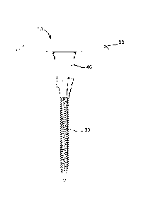
[0013] Fig. 1 is a side elevational view of an assembled fastening
assembly including a plate, a tube and a fastener;
- 3 -
CA 02805585 2013-01-15
WO 2012/012492
PCT/US2011/044622
[0014] Fig. 2 is a central sectional view of the fastening assembly of
Fig. 1;
[0015] Fig. 3 is a sectional view of the fastening assembly of Fig. 1 as
installed in a roof installation shown in section for securing insulation to a
roof
deck;
[0016] Fig. 4 is a top plan view of a plate, a tube and a fastener for
the
fastening assembly of Fig. 1;
[0017] Fig. 5 is an enlarged perspective view of a tube which may be
employed in the fastening assembly of Fig. 1;
[0018] Fig. 6 is a central sectional view of the tube of Fig. 5, taken
along line 6-6 thereof;
[0019] Fig. 7 is a top plan view of the tube of Fig. 5;
[0020] Fig. 8 is a cross-sectional view of the tube of Fig. 5, taken
along
line 8-8 thereof;
[0021] Fig. 9 is a cross-sectional view of the tube of Fig. 5, taken
along
line 9-9 thereof;
[0022] Fig. 10 is a bottom plan view of the tube of Fig. 6;
[0023] Fig. 11 is an enlarged side elevational view of another
embodiment of a tube which may be employed for the fastening system of
Fig. 1;
[0024] Fig. 12 is a central sectional view of a second alternate
embodiment of a tube;
[0025] Fig. 13 is a central sectional view of a third alternate
embodiment of a tube;
[0026] Fig. 14 is a perspective half-sectional view of the tube of Fig.
11;
[0027] Fig. 15 is a top plan view of the tube of Fig. 11;
[0028] Fig. 16 is an enlarged perspective view of a plate for the
fastening assembly of Fig. 1;
[0029] Fig. 17 is an enlarged central sectional view, partly in diagram
form, of the plate of Fig. 16;
[0030] Fig. 18 is an enlarged side view, partly in diagram form, of a
fastener that may be employed in the fastening assembly of Fig. 1;
[0031] Fig. 19 is a side view, partly in diagram form, of a second
fastener that may be employed in the fastening assembly of Fig. 1;
- 4 -
CA 02805585 2013-01-15
WO 2012/012492
PCT/US2011/044622
[0032] Fig. 20 is a central sectional view, partly in diagram form, of
the
tube of Fig. 5;
[0033] Fig. 21 is a perspective view of an alternative embodiment of a
plate which may be employed in a fastening assembly;
[0034] Fig. 22 is a sectional view of the plate of Fig. 21;
[0035] Fig. 23 is a bottom perspective view of the plate of 21
assembled with a tube as employed for the fastening assembly;
[0036] Fig. 24 is a sectional view of the assembled plate and tube of
Fig. 23;
[0037] Fig. 25 is a top plan view of an alternative embodiment of a tube
which may be employed in the fastening assembly;
[0038] Fig. 26 is a perspective view of the tube of Fig. 25 and looking
into the tube interior; and
[0039] Fig. 27 is a central sectional view of the tube of Fig. 25.
DETAILED DESCRIPTION
[0040] With reference to the drawings wherein like numerals represent
like parts throughout the several figures, a fastening assembly designated
generally by the numeral 10 is employed to secure insulation 12 and a water
impermeable membrane 14 to a roof deck 16 and to maintain the connection
between the membrane and the roof deck. In the illustrated installation of
Fig.
3, the roof deck 16 has a corrugated steel form, and the insulation 12 is
typically a highly compressible insulation which may have a thickness which
varies, for example, from 8 to 12 inches.
[0041] In installations for which the fastening assembly 10 has
particular application, battens or rolls of the insulation are laid onto the
roof
deck. The roof is typically a "flat" type of roof. A membrane covers the
insulation. The fastening assembly 10 functions to clamp the membrane and
the insulation onto the roof deck to secure same therewith. Naturally,
numerous such fastening assemblies are employed for a given installation
and typically form a grid across the roof.
[0042] The fastening assembly comprises a plate 20, a fastener 30
which is driven into the roof deck to provide the securing/clamping function,
and a tube 40 which is inserted into the plate and receives fastener 30 which
- 5 -
CA 02805585 2013-01-15
WO 2012/012492
PCT/US2011/044622
is inserted into the tube. The foregoing three components may be pre-
assembled.
[0043] With additional reference to Figs. 16-17, the plate 20 is
typically
made from galvanized steel or other metal and formed by a stamping process.
The plate 20 typically has a stepped circular shape with a central circular
opening 22 and a raised annular platform 24. The plate includes an outer
peripheral lower annular rim 26 and an inner stepped recess 28 which
surrounds the opening 22 and tapers downwardly in two steps from the raised
platform 24. One or more stress cuts 27 may be formed in the plate portion
defining the recess around the opening. For some embodiments, heat-
activated adhesive (not illustrated) may be applied to the platform 24 for
sealing and securing an overlying membrane. The plate 20 may also include
a vent opening 29.
[0044] The tube 40 is an integral, one-piece plastic member. The tube
40 is preferably formed from polyamide with 0 to 15% glass filler and 0 to 3%
impact modifier or polypropylene with 0 to 20% glass filler and 0 to 10%
impact modifier. Other materials may also be suitable.
[0045] The tube 40 includes an annular flange-like collar 42 configured
to be received in the plate recess 28. The collar underside 44 engages the
plate portion defining the recess 28 surrounding the opening of the plate. The
tube 40 functions to facilitate the clamping securement of the plate and in
part
as a relief structure to allow the installed fastening assembly to accommodate
a downwardly compressive load applied at or adjacent the top of the plate
without jeopardizing the integrity of the membrane and the clamp load
supplied by the fastening assembly after the compressive load is relieved.
The tube 40 includes a sleeve-like cylindrical throat portion 50 generally
extending from the underside 44 of the collar and a quasi- conical distal
tapered portion 60. The tube 40 is especially configured to be compatible with
and capable of accommodating fasteners of different dimensions.
[0046] The cylindrical throat portion 50 includes a pair of opposed,
inverted quasi-U-shaped cutouts 52. Each cutout surrounds a resilient tab 54
which projects upwardly. Each tab 54 has an upper shoulder 56 preferably
having a top planar surface. Each tab 54 has a ramp surface 55 configured
and dimensioned to slide over the edge of the plate opening 22 so that the
- 6 -
CA 02805585 2013-01-15
WO 2012/012492
PCT/US2011/044622
shoulder 56 engages the underside 44 of the plate when the tube 40 is
inserted through the central opening 22 and seated in the recess 28. The
outside diameter of the cylindrical throat portion 50 is generally dimensioned
to be closely received in the opening 22 of the plate so that the collar 42 is
seated in the recess 28, and the opposed tab shoulders 56 engage the
underside 44 of the plate whereby the tube may be vertically captured by the
plate. The inner diameter of the inner cylindrical surface 58 of the throat
portion is dimensioned so that the head 32 of the fastener 30 may be easily
passed until the underside 33 of the fastener head 32 engages against an
intermediate shoulder 62 or annular restriction formed at the bottom of the
throat portion.
[0047] The tapered portion 60 includes an upper interior annular recess
region at the interface with the throat portion 50. The tapered portion 60 is
configured so that the effective inside diameter is variable as a function of
the
thread/shank diameter of the associated fastener 30. The tapered portion in a
first mode is dimensioned to be approximately the outside diameter of a
fastener having a first diameter. The axial end of the tapered portion
includes
an opening 70 through which the tip and end portion of the shank of the
fastener passes. Angularly spaced vertical slots 66 are formed at the end of
the tapered portion. The slots 66 function to allow the tapered portion to
flex
generally radially to accommodate fasteners with different diameters.
[0048] In addition, inwardly protruding crush ribs 68 are effectively
displaced radially and/or at least partially destroyed when a larger diameter
fastener is driven into the tube. Naturally, the tapered portion 60 has an
effective fastener diameter range and has a limit for effectively
accommodating fasteners of a given diameter.
[0049] The conical portion is traversed by angularly spaced gusset
grooves 69 to provide reinforcement for the tube. The tapering and geometry
of the tube facilitates the insertion of the tube into the insulation and the
membrane.
[0050] The fastener 30 includes a head 32 with a hex head, a Phillips-
type slot, a square drive recess or other configuration adapted for
engagement by a driving tool for torquably driving the fastener. The shank 34
of the fastener includes a thread 36 which may be a buttress thread and
- 7 -
CA 02805585 2013-01-15
WO 2012/012492
PCT/US2011/044622
terminates in a drill tip 38. Two suitable fasteners 30A and 30B are
illustrated
in Figs. 18 and 19, respectively. Other fasteners are also possible.
[0051] With reference to Fig. 18, fastener 30A is a #15 RoofGripTM
fastener marketed by OMG, Inc. of Agawam, Massachusetts. The head 32A
has a #3 Phillips recess. The major diameter D of the thread 36 is 0.250 to
0.275 inches and the minor diameter d of the thread is 0.165 to 0.175 inches.
The thread 36A is a buttress thread having a pitch of 13 TPI. The shaft length
A may vary from 1 1/4 to 22 inches and the thread 36B length B (including the
drill tip 38A) may vary from 1 1/4 to 4 inches.
[0052] Another suitable embodiment for the fastener is fastener 32B
illustrated in Fig. 19. The fastener 30B is a RhinoBondTM heavy duty drill
point
fastener marketed by OMG, Inc. of Agawam, Massachusetts. The head 32B
has a #3 square drive. The thread has a major diameter of D 0.226 to 0.230
inches and a minor diameter d of 0.175 inches. The thread 36B is a single
lead thread with a pitch of 20 TPI and is a type AB thread. The drill tip 38B
is
a % inch drill tip with a nominal diameter N of 0.208 to 0.212 inches. The
shaft length L varies from 4 inches to 10 inches and the thread length f
(including the drill tip 38B) is approximately 3.860 inches.
[0053] With reference to Figs. 11-15, the tube may assume a number
of alternative forms. Tube 140 illustrated in Figs. 11, 14 and 15 has a
shorter
axial dimension. Four slots 166 are employed. The crush rib 168 structure is
employed at the intermediate interior.
[0054] Tube 240 illustrated in Fig. 12 employs horizontal crush ribs 265
at or slightly below the cylindrical/tapered portion interface and
longitudinally
tapered and extending crush ribs 267 at the interior of the tapered portion
260
of the tube. The interior wall at the distal end of the tapered portion
includes a
dual conical surface 261. An additional set of inwardly tapered ribs 266 are
engageable into the surface 261 in a first position for one diameter and are
forced away from the surface for a second diameter. The horizontal crush
ribs 265 tend to deflect and engage the minor diametral surface of the
fastener in a friction type fit. The longitudinal ribs 267 and, to some
extent,
ribs 261, tend to be damaged and/or sheared off by the fastener. The interior
of the throat prior to the restriction may also include tapered surfaces 251
to
accommodate the multi-dimensioned fasteners.
- 8 -
CA 02805585 2013-01-15
WO 2012/012492
PCT/US2011/044622
[0055] Tube 340 illustrated in Fig. 13 employs inwardly extending axial
ribs 361 adjacent the terminal end of the tapered portion. The ribs cause the
exterior tapered portion 360 of the tube to flex outwardly if a larger
diameter
fastener is employed. Four slots 366 are employed to allow for the terminal
tube flexure to accommodate the enlarged diameter fastener.
[0056] With reference to Figs. 25-27, tube 440 employs inwardly
extending axial ribs 461 which extend interiorly from the upper portion of the
tube and extend longitudinally to the interface with the tapered portion of
the
tube 460. Three slots 466 are employed to allow the terminal tube flexure to
accommodate an enlarged diameter fastener. With additional reference to
Fig. 25, it should be appreciated that the upper cutouts 452, which allows for
the formation of the resilient tabs 454 are configured so that the tabs may be
molded with the tube without employing slides and gates in the molding
process. This latter configuration significantly simplifies the manufacturing
of
the tube.
[0057] It will be appreciated that the geometry and position of the
various inwardly protruding ribs 66, 166, 261, 265, 266, 361 and 461 may
vary. The purpose of the ribs is to provide a stable engagement of the
fastener having a minimal diameter and to allow the tube to expand or flex
outwardly (radially) for larger diameter fasteners while still providing a
tight
semi-quasi-force fit relationship between the fastener and the tube so that
during installation, both are essentially axially aligned about the central
axis of
the fastener and the tube.
[0058] With reference to Fig. 20, the tube employs inwardly protruding
arcuate ribs structures inwardly adjacent the opening at the terminus of the
tapered portion. As illustrated in the drawings, the tapered portions 60 may
flex to accommodate fasteners of different diameters such as, for example,
fasteners having 0.265, 0.274, 0.283, 0.288 inch diameters D1, D2, D3 and
D4. Diameter D5 is slightly less than diameter D6 (Fig. 17) of the plate 20.
There is a slight taper, for example, of 1 at the interior upper portions of
the
throat portion 50 as well as at the terminal inner surface of the terminal
tapered portion 60. Naturally, other dimensions are also possible.
[0059] Upon installation, the tube 40 is inserted into the opening and a
fastener 30 is inserted into the tube. The end of the fastener may project
- 9 -
CA 02805585 2013-01-15
WO 2012/012492
PCT/US2011/044622
through the opening 70. The foregoing components may be pre-assembled
(typically loosely) prior to delivery to the installation site. The
plate/tube/fastener is then positioned over the insulation, and in some
installations, the membrane, at a pre-established anchoring location. It
should
be appreciated that for some installations, such as, for example, those that
employ the OMG RhinoBond system, the membrane is placed over the
plates and bonded to the plate by heat activated adhesive. The tube
penetrates the insulation and, in some installations, the membrane. The
driving tool is coupled to the head 32 and the fastener torqued until the
thread
36 engages into the roof deck 16 at a pre-established penetration depth. The
underside of the fastener head engages the shoulder in the tube. The tabs 54
engage the underside of the plate. Downward displacement of the tube under
the securement load of the fastener results in downward displacement of the
plate until the proper securement by the fastener is attained. It will be
appreciated that the insulation and overlying membrane are compressed or
clamped between the plate and the roof deck for securing same.
[0060] With
reference to Figs. 21-24, an alternate embodiment of a
plate which may be employed with respect to the connection with the
fastening assembly is generally designated by the numeral 120. The plate
includes a plurality of angularly spaced, generally trapezoidal prongs 121
which project downwardly and inwardly from the inner stepped recess 128
which surrounds the opening 122. The prongs 121 resiliently engage against
the upper underside portion of the tube 40, as best illustrated in Fig. 23. In
addition, opposed prongs also engage the shoulders 56 of the resilient tabs
54, as best illustrated in Fig. 24.
[0061] It should
be appreciated that the configuration of the tube and
the assembled relationship between the plate, the tube and the fastener
cooperate to normalize the fracture area per unit of load carrying area of the
tube between the conical transition and the flange transition. This latter
relationship is implemented so that tensile stresses applied to the fastener
system are applied along the length of the tube and any tensile failure would
ultimately occur, if at all, at the strongest failure resistant structure.
- 10 -
CA 02805585 2016-01-21
(00621 The foregoing
installation process is replicated for numerous
fastening assemblies as required to properly secure the membrane and
insulation.
[0063] For applications
wherein an additional membrane is mounted
over the plates and membranes, and the plates include a heat-activated
adhesive, an induction tool (not illustrated) may be used to activate the
adhesive and seal and secure the upper membrane to the plates.
[0064] If an excessive
pressure is applied to the plate or adjacent the
plate to compress the insulation so that the spacing between the plate and the
deck is decreased, the tube is forced downwardly and slides along the shaft of
the fastener. The head of the fastener remains fixed relative to the deck.
Upon removal of the compressive load, the assembly resumes normal clamp
engagement with the tube and the plate.
[0065] A heavy driller (not
illustrated) for steel purlin applications is
preferably employed for driving the fastener. One single tube 40 as described
may provide a friction fit with multiple dimensional fasteners which may be
either a #15 RoofGripT" screw or an OMG Purlin Fastener screw, or a 14 HX
or HD screw with a buttress thread marketed by OMG, Inc. of Agawam,
Massachusetts.
1.00661 While preferred
embodiments of the foregoing have been set
forth for the purposes of illustration, the foregoing description should not
be
deemed a limitation of the invention herein. Accordingly, various
modifications, adaptations and alternatives may occur to one skilled in the
art.
The scope of the claims should not be limited by the preferred embodiments
set forth in the examples, but should be given the broadest interpretation
consistent with the description as a whole.
- 11 -