Note: Descriptions are shown in the official language in which they were submitted.
CA 02805781 2014-03-05
BATTERY HEATING CIRCUIT
Technical Field of the Invention
The present invention pertains to electric and electronic field, in particular
to a battery
heating circuit.
Background of the Invention
In view cars have to run under complex road conditions and environmental
conditions or
some electronic devices are used under harsh environmental conditions, the
battery, which
serves as the power supply unit for electric motor cars or electronic devices,
must be adaptive to
these complex conditions. In
addition, besides these conditions, the service life and
charging/discharging cycle performance of battery must be considered;
especially, when electric
motor cars or electronic devices are used in low temperature environments, the
battery must
have outstanding low temperature charging/discharging performance and higher
input/output
power.
Usually, under low temperature conditions, the resistance of battery will
increase, and the
polarization will increase; therefore, the capacity of battery will be
reduced.
It may be desirable in some cases to keep the capacity of batteries and
improve the
charging/discharging performance of batteries under low temperature
conditions.
Summary of the Invention
In one aspect, an embodiment of the present invention provides a battery
heating circuit,
which may solve the problem of decreased capacity of battery caused by
increased resistance
and polarization of battery under low temperature conditions.
An embodiment of the present invention provides a battery heating circuit,
comprising a
plurality of switch units, a switching control module, a damping element, an
energy storage
circuit, and a polarity inversion unit, wherein, the energy storage circuit is
connected with the
battery, and comprises a current storage element and a plurality of charge
storage elements; the
plurality of charge storage elements are connected with the plurality of
switch units in series in
one-to-one correspondence to form a plurality of branches; the plurality of
branches are
connected in parallel with each other and then connected with the current
storage element and
1
CA 02805781 2014-03-05
the damping element in series; the switching control module is connected with
the switch units,
and is configured to control ON/OFF of the switch units, so that the energy
flows to and fro
between the battery and the energy storage circuit when the switch units
switch on; the polarity
inversion unit is connected with the energy storage circuit, and is configured
to invert the
voltage polarity of the plurality of charge storage elements after the switch
units switch from
ON state to OFF state.
Some other characteristics and advantages of the present invention will be
further detailed
in the embodiments hereunder.
Brief Description of the Drawings
The accompanying drawings are provided here to facilitate further
understanding on the
present invention, and are a part of this document. They are used together
with the following
embodiments to explain the present invention, but shall not be comprehended as
constituting
any limitation to the present invention. In the figures:
Figure 1 is a schematic diagram of the battery heating circuit provided in the
present
invention;
Figure 2 is a schematic diagram of an embodiment of the switch unit shown in
Figure 1;
Figure 3 is a schematic diagram of an embodiment of the switch unit shown in
Figure 1;
Figure 4 is a schematic diagram of an embodiment of the switch unit shown in
Figure 1;
Figure 5 is a schematic diagram of an embodiment of the switch unit shown in
Figure 1;
Figure 6 is a schematic diagram of an embodiment of the switch unit shown in
Figure 1;
Figure 7 is a schematic diagram of an embodiment of the switch unit shown in
Figure 1;
Figure 8 is a schematic diagram of an embodiment of the polarity inversion
unit shown in
Figure 1;
Figure 9 is a schematic diagram of an embodiment of the polarity inversion
unit shown in
Figure 1;
Figure 10 is a schematic diagram of an embodiment of the one-way switch shown
in
Figure 8 and Figure 9;
Figure 11 is a schematic diagram of an embodiment of the battery heating
circuit provided
in the present invention;
Figure 12 shows the wave pattern corresponding to the battery heating circuit
shown in
Figure 11;
2
= CA 02805781 2014-03-05
=
Figure 13 is a schematic diagram of another embodiment of the battery heating
circuit
provided in the present invention;
Figure 14 is a schematic diagram of another embodiment of the battery heating
circuit
provided in the present invention.
Detailed Description of the Embodiments
Hereunder the embodiments of the present invention will be detailed, with
reference to the
accompanying drawings. It should be appreciated that the embodiments described
here are only
provided to describe and explain the present invention, but shall not be
deemed as constituting
any limitation to the present invention.
Please note: unless otherwise specified, where mentioned in the following
text, the term
"switching control module" refers to any controller that can output control
commands (e.g.,
pulse waveform) under preset conditions or at preset times and thereby
controls the switch unit
connected to it to switch on or switch off accordingly, for example, the
switching control
module can be a PLC (Programmable Logic Controller); where mentioned in the
following text,
the term "switch" refers to a switch that achieve ON/OFF control by means of
electrical signals
or achieve ON/OFF control on the basis of the characteristics of the element
or component,
which is to say, the switch can be an one-way switch (e.g., a switch composed
of a two-way
switch and a diode connected in series, which can switch on in one direction)
or a two-way
switch (e.g., a Metal Oxide Semiconductor Field Effect Transistor (MOSFET) or
an IGBT
(Insulated Gate Bipolar Translator) with an anti-parallel freewheeling diode);
where mentioned
in the following text, the term "two-way switch" refers to a switch that can
switch on in two
ways, which can achieve ON/OFF control by means of electrical signals or
achieve ON/OFF
control on the basis of the characteristics of the element or component, for
example, the two-
way switch can be a MOSFET or an IGBT with an anti-parallel freewheeling
diode; where
mentioned in the following text, the term "one-way
3
CA 02805781 2013-01-17
WO 2012/013077 PCT/CN2011/074461
semiconductor element" refers to a semiconductor element that can switch on in
one direction,
such as an diode; where mentioned in the following text, the term "charge
storage element"
refers to any device that can implement charge storage, such as a capacitor;
where mentioned
in the following text, the term "current storage element" refers to any device
that can store
current, such as an inductor; where mentioned in the following text, the term
"forward
direction" refers to the direction in which the energy flows from the battery
to the energy
storage circuit, and the term "reverse direction" refers to the direction in
which the energy
flows from the energy storage circuit to the battery; where mentioned in the
following text,
the term "battery" comprises primary battery (e.g., dry battery or alkaline
battery, etc.) and
secondary battery (e.g., lithium-ion battery, nickel-cadmium battery, nickel-
hydrogen battery,
or lead-acid battery, etc.); where mentioned in the following text, the term
"damping element"
refers to any device that inhibits current flowing and thereby achieves energy
consumption,
such as a resistor; where mentioned in the following text, the term "main
loop" refers to a
loop composed of battery, damping element, switch unit and energy storage
circuit connected
in series.
It should be noted specially: in view different types of batteries have
different
characteristics, in the present invention, the "battery" refers to an ideal
battery that doesn't
have internal parasitic resistance and inductance or has very low internal
parasitic resistance
and inductance, or refers to a battery pack that has internal parasitic
resistance and inductance;
therefore, those skilled in the art should appreciate: if the battery is an
ideal battery that
doesn't have internal parasitic resistance and inductance or has very low
internal parasitic
resistance and inductance, the damping element R refers to an damping element
external to
the battery; if the battery is a battery pack that has internal parasitic
resistance and inductance,
the damping element R refers to a damping element external to the battery, or
refers to the
parasitic resistance in the battery pack.
To ensure the normal service life of the battery, the battery can be heated
under low
temperature condition, which is to say, when the heating condition is met, the
heating circuit
is controlled to start heating for the battery; when the heating stop
condition is met, the
heating circuit is controlled to stop heating.
In the actual application of battery, the battery heating condition and
heating stop
4
CA 02805781 2013-01-17
WO 2012/013077 PCT/C1N2011/074461
condition can be set according to the actual ambient conditions, to ensure
normal
charging/discharging performance of the battery.
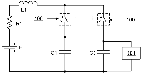
In order to heat up the battery E located in the low temperature environment,
the present
invention provides a battery heating circuit; as shown in figure 1, the
battery heating circuit
comprises a plurality of switch units 1, a switching control module 100, a
damping element
R1, an energy storage circuit, and a polarity inversion unit 101, wherein, the
energy storage
circuit is connected with the battery, and comprises a current storage element
Li and a
plurality of charge storage elements Cl; the plurality of charge storage
elements Cl are
connected with the plurality of switch units 1 in series in one-to-one
correspondence to form a
plurality of branches; the plurality of branches are connected in parallel
with each other and
then connected with the current storage element Li and damping element RI in
series; the
switching control module 100 is connected with the switch units 1, and is
configured to
control ON/OFF of the switch units 1, so that the energy flows to and fro
between the battery
and the energy storage circuit when the switch units 1 switch on; the polarity
inversion unit
101 is connected with the energy storage circuit, and is configured to invert
the voltage
polarity of the plurality of charge storage elements Cl after the switch units
1 switch from ON
state to OFF state.
It should be noted specially that in view different types of batteries have
different
characteristics, in the present invention, if the battery E has very high
internal parasitic
resistance and parasitic inductance, the damping element R1 could refers to
the parasitic
resistance in the battery pack; likewise, the current storage element L2 could
refers to the
parasitic inductance in the battery pack.
The switching control module 100 can control the energy to flow from the
battery E to
the charge storage elements Cl at the same time or in sequence, and control
the energy to
flow from the charge storage elements Cl to the battery E at the same time or
in sequence, by
controlling the switch units 1. Wherein, the control of energy flow to the
charge storage
elements Cl "at the same time" and energy flow back to the battery E "at the
same time" can
be implemented by controlling the switch units in the plurality of branches to
switch on at the
same time. The control of energy flow to the charge storage elements Cl "in
sequence" and
energy flow back to the battery E "in sequence" can be implemented by
controlling the switch
CA 02805781 2013-01-17
units 1 in the plurality of branches to switch on in an appropriate sequence.
For example, the
plurality of switch units 1 can be controlled to switch on at different times,
so that energy
charge/discharge can be accomplished through the plurality of branches at
different times;
or, the plurality of switch units 1 can be grouped into switch unit groups,
wherein, the switch
units in each switch unit group can be controlled to switch on at the same
time, while the
switch unit groups can be controlled to switch on at different times; in that
way, energy
charge/discharge can be accomplished through the respective branches
corresponding to the
respective switch unit groups at different times. Preferably, the switching
control module
100 controls the switch units 1 in a way that the energy can flow from the
battery E to the
plurality of charge storage elements Cl at the same time and flow from the
charge storage
elements Cl back to the battery E in sequence. In such an embodiment, when the
current
flows in forward direction, the battery E discharges; in that state, the
plurality of charge
storage elements Cl can be connected with the battery E at the same time, so
as to increase
the current; when the current flows in reverse direction, the battery E is
charged; in that
state, the plurality of charge storage elements Cl can be connected with the
battery E in
sequence, so as to decrease the current flow through the battery E.
The switch units 1 can be implemented in a plurality of ways. The present
invention
doesn't define any limitation to the specific implementation of the switch
units. In an
embodiment of the switch units 1, the switch units I are a two-way switch K3,
as shown in
Figure 2. The switching control module 100 controls ON/OFF of the two-way
switch K3;
when the battery is to be heat up, the two-way switch K3 can be controlled to
switch on; if
heating is to be paused or is not required, the two-way switch K3 can be
controlled to switch
off.
Employing a separate two-way switch K3 to implement the switch unit 1 can
simplify the
circuit, reduce system footprint, and facilitate the implementation; however,
to implement
cut-off of reverse current, the following preferred embodiment of the switch
unit 1 is further
provided in the present invention.
Preferably, the switch unit 1 comprises a first one-way branch configured to
enable
energy flow from the battery E to the energy storage circuit, and a second one-
way branch
configured to enable energy flow from the energy storage circuit to the
battery E; wherein,
the switching
6
CA 02805781 2013-01-17
WO 2012/013077 PCT/CN2011/074461
control module 100 is connected to either or both of the first one-way branch
and second
one-way branch, to control ON/OFF of the connected branches.
When the battery is to be heated, both the first one-way branch and the second
one-way
branch can be controlled to switch on; when heating is to be paused, either or
both of the first
one-way branch and the second one-way branch can be controlled to switch off;
when heating
is not required, both of the first one-way branch and the second one-way
branch can be
controlled to switch off. Preferably, both of the first one-way branch and the
second one-way
branch are subject to the control of the switching control module 100; thus,
energy flow
cut-off in forward direction and reverse direction can be implemented
flexibly.
In another embodiment of the switch unit 1, as shown in Figure 3, the switch
unit 1 may
comprise a two-way switch K4 and a two-way switch K5, wherein, the two-way
switch K4
and the two-way switch K5 are connected in series opposite to each other, to
form the first
one-way branch and the second one-way branch; the switching control module 100
is
connected with the two-way switch K4 and the two-way switch K5 respectively,
to control
ON/OFF of the first one-way branch and the second one-way branch by
controlling ON/OFF
of the two-way switch K4 and two-way switch K5.
When the battery is to be heated, the two-way switches K4 and K5 can be
controlled to
switch on; when heating is to be paused, either or both of the two-way switch
K4 and
two-way switch K5 can be controlled to switch off; when heating is not
required, both of the
two-way switch K4 and two-way switch K5 can be controlled to switch off. In
such an
implementation of switch units 1, the first one-way branch and the second one-
way branch
can be controlled separately to switch on or off, and therefore energy flow
cut-off in forward
direction and reverse direction in the circuit can be implemented flexibly.
In another embodiment of switch unit 1, as shown in Figure 5, the switch unit
1 may
comprise a switch K6, a one-way semiconductor element Dll, and a one-way
semiconductor
element D12, wherein, the switch K6 and the one-way semiconductor element D11
are
connected in series with each other to form the first one-way branch; the one-
way
semiconductor element Dl 2 forms the second one-way branch; the switching
control module
100 is connected with the switch K6, to control ON/OFF of the first one-way
branch by
controlling ON/OFF of the switch K6. In the switch unit 1 shown in Figure 11,
when heating
7
CA 02805781 2013-01-17
is required, the switch K6 can be controlled to switch on; when heating is not
required, the
switch K6 can be controlled to switch off.
Though the implementation of switch unit 1 shown in Figure 5 enables to-and-
fro energy
flow along separate branches, it cannot enable energy flow cut-off function in
reverse
direction. The present invention further puts forward another embodiment of
switch unit 1;
as shown in Figure 6, the switch unit 1 can further comprise a switch K7 in
the second one-
way branch, wherein, the switch K7 is connected with the one-way semiconductor
element
D12 in series, the switching control module 100 is also connected with the
switch K7, and is
configured to control ON/OFF of the second one-way branch by controlling
ON/OFF of the
switch K7. Thus, in the switch unit 1 shown in Figure 6, since there are
switches (i.e., switch
K6 and switch K7) in both one-way branches, energy flow cut-off function in
forward
direction and reverse direction is enabled simultaneously.
Preferably, the switch unit 1 can further comprise a resistor, which is
connected in series
with the first one-way branch and/or the second one-way branch and is
configured to reduce
the current in the heating circuit for the battery E and to avoid damage to
the battery E
resulted from over-current in the circuit. For example, a resistor R6
connected in series with
the two-way switch K4 and the two-way switch K5 can he added in the switch
unit 1 shown
in Figure 3, to obtain another implementation of the switch unit 1, as shown
in Figure 4.
Figure 7 also shows an embodiment of the switch unit 1, which is obtained by
connecting
respectively resistor R2 and resistor R3 in series in both the one-way
branches in the switch
unit 1 shown in Figure 6.
In the technical scheme of the present invention, when the battery E is to be
heated up,
the switching control module 100 controls the plurality of switch units 1 to
switch on at the
same time or in sequence, and thereby the battery E and the energy storage
circuits are
connected in series to form a loop, and the battery E charges the charge
storage elements Cl;
when the current in the loop reaches to zero in forward direction after the
peak current, the
charge storage elements Cl begin to discharge, and therefore the current flows
from the
charge storage elements Cl back to the battery E; since both the current flow
in forward
direction and the current flow in reverse direction in the loop flow though
the damping
element R1, the purpose of heating up the battery E is attained by means of
the heat
8
CA 02805781 2013-01-17
WO 2012/013077 PCT/CN2011/074461
generation in the damping element RI. Above charge/discharge process can be
performed
cyclically. When the temperature of the battery E rises to the heating stop
condition, the
switching control module 100 can control the switch units 1 to switch off, and
thereby the
heating circuit will stop operation.
In the heating process described above, when the current flows from the energy
storage
circuit back to the battery E, the energy in the charge storage elements Cl
will not flow back
to the battery E completely; instead, some energy will remain in the charge
storage elements
Cl, and ultimately the voltage across the charge storage elements Cl is close
or equal to the
voltage of the battery, and therefore the energy flow from the battery E to
the charge storage
elements Cl can't continue any more; that phenomenon is adverse to the cyclic
operation of
the heating circuit. Therefore, after the switch units 1 switch from ON state
to OFF state, the
voltage polarity of the charge storage elements Cl is inverted by means of a
polarity inversion
unit 101 in the present invention; since the voltage across the charge storage
elements Cl can
be added serially with the voltage of the battery E after polarity inversion,
the discharging
current in the heating circuit can be increased when the switch units I switch
on again. The
switch units 1 can be controlled to switch off at any time in one or more
cycles; the switch
units 1 can be controlled to switch off at any time, for example, when the
current flow in the
circuit is in forward direction/reverse direction, and when the current flow
is zero or not zero.
A specific implementation form of switch units 1 can be selected, depending on
the required
cut-off strategy; if current flow cut-off in forward direction is only
required, the
implementation form of switch units 1 shown in Figure 2 or Figure 5 can be
selected; if
current flow cut-off in forward direction and reverse direction is required,
the switch units
with two controllable one-way branches shown in Figure 4, Figure 6, or Figure
7 can be
selected. Preferably, the switching control module 100 is configured to
control the switch
units 1 to switch off when the current flow though the switch units I is zero
after the switch
units 1 switch on, so as to improve the working efficiency of the circuit. In
addition, the
disturbance to the entire circuit is minimal if the switch units I switch off
when the current
flow in the circuit is zero.
In an embodiment of the polarity inversion unit 101, the polarity inversion
unit 101
comprises a plurality of circuits, which are connected with the plurality of
charge storage
9
CA 02805781 2013-01-17
WO 2012/013077 PCT/CN2011/074461
elements Cl one-to-one correspondence, wherein, as shown in Figure 8, each
polarity
inversion unit comprises a one-way switch 3 and a current storage element L2
connected in
series with each other; the switching control module 100 is also connected
with the one-way
switches 3, and is configured to invert the voltage polarity of the plurality
of charge storage
elements Cl by controlling the one-way switches to switch on; the inversion
can be
performed for the plurality of charge storage elements Cl at the same time or
in sequence.
In another embodiment of the polarity inversion unit 101, as shown in Figure
9, the
polarity inversion unit 101 comprises a plurality of one-way switches 3 and a
current storage
element L2; wherein, the plurality of one-way switches 3 are connected at one
end to the
plurality of charge storage elements Cl at one end in one-to-one
correspondence; the plurality
of one-way switches 3 are connected at the other end to one end of the current
storage element
L2, and the other end of the current storage element L2 is connected to the
plurality of charge
storage elements Cl at the other end; the switching control module 100 is also
connected with
the one-way switches 3, and is configured to invert the voltage polarity of
the plurality of
charge storage elements Cl at the same time or in sequence by controlling the
one-way
switches 3 to switch on. In such an embodiment, the polarity inversion process
of the plurality
charge storage elements Cl can be implemented with one current storage element
L2;
therefore, the number of elements can be reduced; in addition, preferably, the
switching
control module 100 implements the voltage polarity inversion of the plurality
of the charge
storage elements Cl in sequence by controlling the switch-on times of the
plurality of the
one-way switches 3; in that scheme, since the voltage polarity of the
plurality of the charge
storage elements Cl is not inverted at the same time, the size of the current
storage element
L2 required in the polarity inversion unit 101 can be further reduced, and
therefore the size
and weight of the battery heating circuit can be further reduced.
Wherein, the one-way switch 3 can be any element that can be used to
accomplish
ON/OFF control of a one-way circuit. For example, the one-way switch 3 can be
in the
structure shown in Figure 10, which is to say, the one-way switch 3 can
comprise a one-way
semiconductor element DI and a switch K2 connected in series to each other.
The plurality of
one-way switches can be implemented with a plurality of one-way semiconductor
elements
and switches connected in series; or, they can be implemented by sharing one
switch, for
CA 02805781 2013-01-17
WO 2012/013077 PCT/CN2011/074461
example, a plurality of one-way semiconductor elements can be connected at one
end to one
end of the same switch in series, the one-way semiconductor elements can be
connected at the
other end to a plurality of charge storage elements in one-to-one
correspondence, and the
other end of the switch can be connected to the current storage elements, so
that the number
of switches in the heating circuit can be decreased; or, the plurality of one-
way switches can
be implemented by sharing one one-way semiconductor element, for example, a
plurality of
switches can be connected at one end to one end of a one-way semiconductor
element, the
switches can be connected at the other end to a plurality of charge storage
elements at one end,
and the other end of the one-way semiconductor element can be connected to the
current
storage elements, so that the number of one-way semiconductor elements in the
heating
circuit can be decreased. The present invention doesn't define any limitation
to the specific
implementation of the one-way switches for the polarity inversion unit 101 in
the heating
circuit, as long as the implementation can accomplish the control of the
polarity inversion
process of the plurality of charge storage elements.
Hereunder the working process of the embodiments of the heating circuit for
battery E
will be introduced, with reference to the Figure 11-14, wherein, Figure 11,
Figure 13, and
Figure 14 show different embodiments of the heating circuit for battery E, and
Figure 12
shows the wave pattern corresponding to the heating circuit for battery E
shown in Figure 11.
It should be noted: though the features and elements of the present invention
are described
specifically with reference to Figure 11, 13, and 14, each feature or element
of the present
invention can be used separately without other features and elements, or can
be used in
combination or not in combination with other features and elements. The
embodiments of the
heating circuit for battery E provided in the present invention are not
limited to those shown
in Figure 11, 13, and 14. The grid part of the wave pattern shown in Figure 12
indicates that
drive pulses can be applied to the switch in one or more times within the
period, and the pulse
width can be adjusted as required.
In the heating circuit for battery E shown in Figure 11, the switch units 1
are in the form
of two-way switches (i.e., two-way switch K 1 a and K lb); the two-way switch
Kla is
connected with a charge storage element Cla in series to form a first branch,
and the two-way
switch Klb is connected with a charge storage element C lb in series to form a
second branch;
11
CA 02805781 2013-01-17
WO 2012/013077 PCT/CN2011/074461
both of the two branches are connected with the current storage element Li,
damping element
R1, and battery E in series. The polarity inversion units 101 share one
current storage element
L2; the one-way semiconductor element D la and switch K2a as well as the one-
way
semiconductor element Dlb and switch K2b form two one-way switches 3,
respectively, and
are configured to control the polarity inversion process of charge storage
element CI a and
Clb, respectively. The switching control module can control ON/OFF of Kla,
Klb, K2a, and
K2b. Figure 12 shows the wave patterns of current IC la through the charge
storage element
C 1 a and the voltage VC1a across the charge storage element C 1 a as well as
the current IC lb
through the charge storage element Clb and the voltage VC1b across the charge
storage
element Clb; the heating circuit shown in Figure 11 can operate through the
following
procedures:
a) The switching control module 100 controls the two-way switch K1 a and Klb
to
switch on, as indicated by the time period ti in Figure 12; thus, the battery
E can discharge in
forward direction through the loop composed of two-way switch K1 a and charge
storage
element Cl a and the loop composed of two-way switch Klb and charge storage
element C lb
(as indicated by the positive half cycles of current IC1 a and IC1b in the
time period ti in
Figure 12), and can be charged in reverse direction (as indicated by the
negative half cycles of
current ICla and IC1b in the time period ti in Figure 12);
b) The switching control module 100 controls the two-way switch Kl a and Klb
to
switch off when the current in reverse direction is zero.
c) The switching control module 100 controls the switch K2b to switch on, and
thus the
charge storage element C lb discharges through the loop composed of one-way
semiconductor
element D lb, current storage element L2, and switch K2b, and attain the
purpose of voltage
polarity inversion, and then, the switching control module 100 controls the
switch K2b to
switch off, as indicated by the time period t2 in Figure 12;
d) The switching control module 100 controls the switch K2a to switch on, and
thus the
charge storage element Cla discharges through the loop composed of one-way
semiconductor
element Dl a, current storage element L2, and switch K2a, and attain the
purpose of voltage
polarity inversion, and then, the switching control module 100 controls the
switch K2a to
switch off, as indicated by the time period t3 in Figure 12;
12
CA 02805781 2013-01-17
WO 2012/013077 PCT/CN2011/074461
e) The step a) to step d) are repeated; thus, the battery E is heated up
continuously in the
charge/discharge cycles, till the battery E meets the heating stop condition.
In the heating circuit for battery E shown in Figure 13, the switch units 1
are still in the
form of two-way switches shown in Figure 11 (i.e., two-way switch Kla and
Klb); the
two-way switch Kla is connected with a charge storage element C la in series
to form a first
branch, and the two-way switch Klb is connected with a charge storage element
C lb in series
to form a second branch; both of the two branches are connected with the
current storage
element Li, damping element RI, and battery E in series. The polarity
inversion units 101
still share one current storage element L2; however, different to the polarity
inversion units
shown in Figure 11, the polarity inversion units in Figure 13 employ one-way
semiconductor
element Dla and switch K2a and switch K2b as one-way switches in them,
wherein, the
switch K2a and K2b are connected at one end to one end of the one-way
semiconductor
element Dl a, and the switch K2a and K2b are connected at the other end to
charge storage
element Cla and C lb, respectively; the other end of the one-way semiconductor
element Dla
is connected to the current storage element L2. The switching control module
100 can control
ON/OFF of Kla, Klb, K2a, and K2b, so as to control the working process of the
entire
heating circuit. Compared to the heating circuit shown in Figure 11, the
heating circuit for
battery E shown in Figure 13 is slightly different only in the circuit
structure of one-way
switches in the polarity inversion units 101, while the operating process is
essentially the
same. Therefore, it will not be further detailed here.
In the heating circuit for battery E shown in Figure 14, the switch units 1
are still in the
form of two-way switches shown in Figure 11 (i.e., two-way switch Kla and
Klb); the
two-way switch Kla is connected with a charge storage element C la in series
to form a first
branch, and the two-way switch Klb is connected with a charge storage element
C lb in series
to form a second branch; both of the two branches are connected with the
current storage
element Li, damping element RI, and battery E in series. The polarity
inversion units 101
still share one current storage element L2; however, different to the polarity
inversion units
shown in Figure 11, the polarity inversion units in Figure 14 employ one-way
semiconductor
element DI a, one-way semiconductor element Dl b, and switch K2a as one-way
switches in
them, wherein, the one-way semiconductor element Dla and one-way semiconductor
element
13
CA 02805781 2013-01-17
WO 2012/013077 PCT/CN2011/074461
Dlb are connected at one end to one end of the switch K2a, the one-way
semiconductor
element D1 a and one-way semiconductor element DI b are connected at the other
end to the
charge storage element Cl a and C lb, respectively, and the other end of the
switch K2a is
connected to the current storage element L2. The switching control module 100
can control
ON/OFF of K1 a, Klb, K2a, and K2b, so as to control the working process of the
entire
heating circuit. When the heating circuit shown in Figure 14 operates, first,
the two-way
switch Kl a can be controlled to switch on, so that the battery E can
discharge and be charged
through the branch of charge storage element Cl; then, the two-way switch Kl a
can be
controlled to switch off, and the switch K2a can be controlled to switch on,
so as to invert the
voltage polarity of the charge storage element Cla; after the voltage polarity
inversion of
charge storage element Cl is accomplished, the switch K2a can be controlled to
switch off;
then, the two-way switch Klb can be controlled to switch on, so that the
battery E can
discharged and be charged through the branch of the charge storage element C
lb; next, the
Iwo-way switch Klb can be controlled to switch off, and the switch K2a can be
controlled to
switch on, so as to invert the voltage polarity of the charge storage element
C lb; after the
voltage polarity inversion of charge storage element C lb is accomplished, the
switch K2a can
be controlled to switch off. The cycles can be repeated, till the condition
for stopping battery
heating is met.
The heating circuit provided in the present invention can improve the
charge/discharge
performance of the battery; in addition, since the energy storage circuit and
switch unit are
connected with the battery in series in the heating circuit, safety problem
related with failures
and short circuit of the switch unit can be avoided when the battery is heated
owing to the
existence of the charge storage element connected in series, and therefore the
battery can be
protected effectively. In addition, a polarity inversion unit is added in the
heating circuit
provided in the present invention; thus, after the switch unit switches off,
the polarity
inversion unit can invert the voltage polarity of the charge storage elements
in the energy
storage circuit; since the voltage across the charge storage element can be
added serially with
the voltage of the battery after polarity inversion, the discharging current
in the heating circuit
can be increased when the switch unit is controlled to switch on at the next
time, and thereby
the working efficiency of the heating circuit can be improved. Moreover, in
preferred
14
CA 02805781 2014-03-05
embodiments of the present invention, a single inductor is employed to
implement polarity
inversion; therefore, the number of elements can be reduced, and thereby the
size and weight of
the battery heating circuit can be reduced.
While some preferred embodiments of the present invention are described above
with
reference to the accompanying drawings, the present invention is not limited
to the details in
those embodiments. Those skilled in the art can make modifications and
variations to the
technical scheme of the present invention, without departing from the ideal of
the present
invention. However, all these modifications and variations shall be deemed as
falling into the
protected domain of the present invention.
In addition, it should be noted: the specific technical features described in
above
embodiments can be combined in any appropriate form, provided that there is no
conflict. To
avoid unnecessary repetition, the possible combinations are not described
specifically in the
present invention. Moreover, the different embodiments of the present
invention can be
combined freely as required, as long as the combinations don't deviate from
the ideal of the
present invention. However, such combinations shall also be deemed as falling
into the scope
disclosed in the present invention.