Language selection

Search

Patent 2806068 Summary

Third-party information liability

Some of the information on this Web page has been provided by external sources. The Government of Canada is not responsible for the accuracy, reliability or currency of the information supplied by external sources. Users wishing to rely upon this information should consult directly with the source of the information. Content provided by external sources is not subject to official languages, privacy and accessibility requirements.

Claims and Abstract availability

Any discrepancies in the text and image of the Claims and Abstract are due to differing posting times. Text of the Claims and Abstract are posted:

  • At the time the application is open to public inspection;
  • At the time of issue of the patent (grant).
(12) Patent: (11) CA 2806068
(54) English Title: AIR-COOLED OIL COOLER FOR TURBOFAN ENGINE
(54) French Title: REFROIDISSEUR D'HUILE REFROIDI A L'AIR POUR UN MOTEUR A TURBINE
Status: Granted and Issued
Bibliographic Data
(51) International Patent Classification (IPC):
  • F02C 07/14 (2006.01)
  • B64D 29/00 (2006.01)
  • B64D 33/10 (2006.01)
  • F01D 25/12 (2006.01)
  • F01D 25/18 (2006.01)
  • F01M 05/00 (2006.01)
  • F02C 07/06 (2006.01)
  • F16N 39/02 (2006.01)
(72) Inventors :
  • ALECU, DANIEL T. (Canada)
(73) Owners :
  • PRATT & WHITNEY CANADA CORP.
(71) Applicants :
  • PRATT & WHITNEY CANADA CORP. (Canada)
(74) Agent: NORTON ROSE FULBRIGHT CANADA LLP/S.E.N.C.R.L., S.R.L.
(74) Associate agent:
(45) Issued: 2020-03-24
(22) Filed Date: 2013-02-14
(41) Open to Public Inspection: 2013-08-24
Examination requested: 2018-02-08
Availability of licence: N/A
Dedicated to the Public: N/A
(25) Language of filing: English

Patent Cooperation Treaty (PCT): No

(30) Application Priority Data:
Application No. Country/Territory Date
13/404,092 (United States of America) 2012-02-24

Abstracts

English Abstract

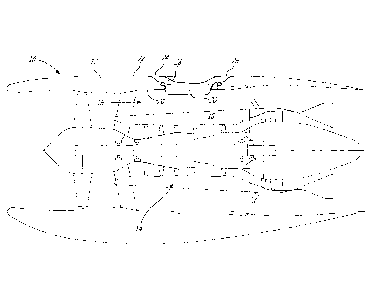
A turbofan gas turbine engine comprises a nacelle cowl and a core engine. A bypass duct is between an outer surface of a casing of the core engine, and an inner surface of the nacelle cowl. An air channel is in the nacelle cowl, an inlet and an outlet of the air channel being in an outer surface of the nacelle cowl. An oil cooler has at least one oil passage for oil circulation, the air cooler having a first heat exchange surface in the air channel exposed to air circulating in the air channel, the air channel having a second heat exchange surface in the bypass duct exposed to air circulating in the bypass duct. A method for cooling oil in a turbofan gas turbine engine is also provided.


French Abstract

Un moteur à turbine à gaz de réacteur à double flux comprenant un capot de nacelle et un moteur central. Un conduit de dérivation se trouve entre une surface extérieure dun carter du moteur central et une surface intérieure du capot de nacelle. Un conduit dair est dans le capot de nacelle, une prise dair et une sortie dair du conduit dair étant situées dans une surface extérieure du capot de nacelle. Un refroidisseur dhuile possède au moins un passage dhuile pour la circulation de lhuile, le refroidisseur dhuile ayant une première surface déchange thermique dans le conduit dair exposé à lair circulant dans le conduit dair, le conduit dair ayant une deuxième surface déchange thermique dans le conduit de dérivation exposé à lair circulant dans le conduit de dérivation. Une méthode pour refroidir lhuile dans un moteur à turbine à gaz de réacteur à double flux est également fournie.

Claims

Note: Claims are shown in the official language in which they were submitted.


Claims:
1. A turbofan gas turbine engine comprising:
a nacelle cowl;
a core engine;
a bypass duct between an outer surface of a casing of the core engine, and an
inner
surface of the nacelle cowl;
an air channel in the nacelle cowl, an inlet and an outlet of the air channel
being in an
outer surface of the nacelle cowl; and
an oil cooler having at least one oil passage for oil circulation, the oil
cooler having a first
heat exchange surface solely in the air channel exposed to air circulating in
the air channel, the
oil cooler having a second heat exchange surface solely in the bypass duct
exposed to air
circulating in the bypass duct.
2. The turbofan gas turbine engine according to claim 1, wherein the first
heat exchange
surface and the second heat exchange surface comprise fins.
3. The turbofan gas turbine engine according to claim 2, wherein the fins
extend lengthwise
in a direction of airflow.
4. The turbofan gas turbine engine according to any one of claims 1 to 3,
further comprising
bleed holes at a rear end of the oil cooler for bleeding air from the bypass
duct to the air channel
to entrain air circulation in the air channel.
5. The turbofan gas turbine engine according to claim 4, further comprising
a Coanda
surface in the air channel adjacent to the bleed holes.
6. The turbofan gas turbine engine according to any one of claims 1 to 5,
wherein the outlet
of the air channel is located at a low pressure location on an outer surface
of the nacelle cowl.
7. The turbofan gas turbine engine according to any one of claims 1 to 6,
wherein a portion
of the nacelle cowl in the environment of the air channel comprises an
ablative foam.
- 6 -

8. The turbofan gas turbine engine according to any one of claims 1 to 7,
wherein a portion
of the air channel comprising the at least one oil passage is generally
coplanar with an outer
surface of the bypass duct
9. The turbofan gas turbine engine according to any one of claims 1 to 8,
wherein at least
one oil passage has an elongated passage portion that is generally axially
oriented in the turbofan
gas turbine engine.
10. A method for cooling oil in a turbofan gas turbine engine, comprising:
circulating oil in an oil cooler in a nacelle cowl;
directing air from an inlet in an outer surface of the nacelle cowl into an
air channel
passing through the nacelle cowl and on a first heat exchange surface of the
oil cooler, said first
heat exchange surface being solely in the air channel; and
directing air of a bypass duct on a second heat exchange surface of the oil
cooler, said
second heat exchange surface being solely in the bypass duct.
11. The method according to claim 10, further comprising entraining air
circulation in the air
channel by bleeding air from the bypass duct into the air channel.
12. The method according to claim 11, wherein bleeding air from the bypass
duct comprises
bleeding air heated by the second heat exchange surface.
13. The method according to any one of claims 10 to 12. further comprising
outletting air
from the air channel at a low pressure location on an outer surface of the
nacelle cowl.
14. The method according to any one of claims 10 to 13, wherein directing
air on the first
heat exchange surface comprises directing air through fins of the oil cooler.
15. The method according to any one of claims 10 to 14, wherein directing
air on the second
heat exchange surface comprises directing air through fins of the oil cooler.
16. The method according to any one of claims 10 to 15, wherein circulating
the oil in the oil
cooler comprises firstly circulating the oil in passages adjacent to the
second heat exchange
- 7 -

surface, and subsequently circulating the oil in passages adjacent to the
first heat exchange
surface.
17. The
method according to any one of claims 10 to 16, wherein circulating the oil in
the oil
cooler comprises circulating the oil in at least one elongated passage portion
that is generally
axially oriented in the turbofan gas turbine engine.
- 8 -

Description

Note: Descriptions are shown in the official language in which they were submitted.


CA 02806068 2013-02-14
AIR-COOLED OIL COOLER FOR
TURBOFAN ENGINE
TECHNICAL FIELD
The application relates generally to turbofan engines and, more particularly,
to an air-cooled oil cooler of a turbonfan engine.
BACKGROUND OF THE ART
Typical engine air cooled oil coolers of turbofan gas turbine engines, known
as surface coolers, are provided with fins on the side facing the engine
bypass
airflow. The heat transfer density per cooler unit area is limited by the
maximum fin
height to reduce perturbations in the bypass duct, and by the air temperature
in the
bypass duct.
Accordingly, there is a need to provide an improved air-cooled oil cooler in
gas turbine engines.
SUMMARY
In one aspect, there is provided a turbofan gas turbine engine comprising: a
nacelle cowl; a core engine; a bypass duct between an outer surface of a
casing of the
core engine, and an inner surface of the nacelle cowl; an air channel in the
nacelle
cowl, an inlet and an outlet of the air channel being in an outer surface of
the nacelle
cowl; and an oil cooler having at least one oil passage for oil circulation,
the air
cooler having a first heat exchange surface in the air channel exposed to air
circulating in the air channel, the air channel having a second heat exchange
surface
in the bypass duct exposed to air circulating in the bypass duct.
In a second aspect, there is provided a method for cooling oil in a turbofan
gas turbine engine, comprising: circulating oil in an oil cooler in a nacelle
cowl;
directing air from an inlet in an outer surface of the nacelle cowl into an
air channel
and on a first heat exchange surface of the oil cooler; and directing air of a
bypass
duct on a second heat exchange surface of the oil cooler.
Further details of these and other aspects of the present invention will be
apparent from the detailed description and figures included below.
- 1 -

CA 02806068 2013-02-14
=
DESCRIPTION OF THE DRAWINGS
Reference is now made to the accompanying figures, in which:
Fig. 1 is a schematic cross-sectional view of a turbofan gas turbine engine
with an air-cooled oil cooler in accordance with the present disclosure;
Fig. 2 is an enlarged sectional view of the turbofan gas turbine engine
showing the air-cooled oil cooler;
Fig.3 is a sectional view of the air-cooled oil cooler of Fig. 2, taken along
sectional line 3-3 of Fig. 2; and
Fig. 4 is an enlarged view of a downstream rear end of the air-cooled oil
cooler.
DETAILED DESCRIPTION OF THE EMBODIMENTS
Fig.1 illustrates a turbofan gas turbine engine 10 of a type preferably
provided for use in subsonic flight, generally comprising a nacelle cowl 12. A
core
engine 14 is axially positioned within the nacelle cowl 12. A bypass duct 16
is
defined between an outer surface of a core casing 18 of the core engine 14 and
an
inner surface 20 of the nacelle cowl 12. The nacelle cowl 12 has the inner
surface 20
and an outer surface 22.
An ambient air scoop 24 (i.e., air inlet) is defined in the nacelle cowl 12,
and
is in the outer surface 22. The ambient air scoop 24 is in fluid communication
with an
air outlet 26, by way of an air channel 28. Accordingly, ambient air enters
via the air
scoop 24, travels through the air channel 28 to then exits via the air outlet
26. The air
outlet 26 may be located as in Fig. 1 at a low pressure location along the
nacelle cowl
12. The air channel 28 is oriented inward of the outer surface of the nacelle
cowl 12
at the air scoop 24. According to an embodiment, the parts of the nacelle cowl
12
surrounding the air channel 28 may include an ablative foam (e.g., injection
molded)
surrounded by low-pressure soft seals.
Referring to Fig. 2, an air-cooled oil cooler 30 (hereinafter ACOC) has a side
thereof partly in the air channel 28 to be exposed to the scooped ambient air.
As
shown in Fig. 3, the ACOC 30 has a body 32 in which oil passages 34 (Fig. 3)
are
-2¨

CA 02806068 2013-02-14
=
defined. The body 32 may be a double wall plate. The body 32 may be generally
coplanar with an inner surface of the nacelle cowl 12, in the bypass duct 16.
The
ACOC 30 may be in a coil configuration with one inlet port and one outlet port
(not
shown) that are part of an oil circuit of the turbofan engine. Other
configurations are
considered as well. For instance, the ACOC 30 may have multiple ports.
The ACOC 30 has a pair of heat exchange surfaces ¨ it is two-sided. One of
the heat exchange surfaces is in the channel 28 and therefore exposed to air
circulating therein, while another of the heat exchange surfaces is in the
bypass duct
16 and therefore exposed to bypass air. Sets of fins 36 and 38 project from
both sides
of the body 32. The fins project either outwardly or inwardly, and may be
radially or
quasi-radially oriented, and therefore extend lengthwise in the direction of
airflow to
be streamlined. Cowl-side fins 36 are located in the air channel 28, whereas
bypass-
side fins 38 project into the bypass duct 16. It is observed that the fins 36
and 38
generally extend in an axial direction with channels defined therebetween.
Accordingly, the air circulating in either one of the air channel 28 and
bypass duct 16
may circulate through the channels between the fins 36 or 38.
Referring to Fig. 2, an assembly of the ACOC 30 in the turbofan engine 12 is
shown in greater detail. According to the illustrated embodiment, the ACOC 30
may
have a flange 40 by which it is connected by way of fasteners 42 to the
nacelle cowl
12. In an embodiment, the flange 40 extends upstream and laterally from the
body 32,
but not downstream. Seals 44 may be provided where appropriate to prevent air
leakage between the ACOC 30 and the nacelle cowl 12.
A wall 46 is located downstream of the ACOC 30. The wall 46 is shown as
having a generally flat wall portion in the bypass duct 16, and an arcuate
wall portion
in the air channel 28. The arcuate surface may be a Coanda convex surface 48.
The
wall 46 is separated from the rear end of the ACOC 30, thereby defining a
nozzle 50.
Alternatively, a rear end of the ACOC 30 may be connected to the wall 46 with
a
plurality of calibration holes in a flange of the ACOC 30, to allow bleed air
to
circulate from the bypass duct 16 to the channel 28. The nozzle 50,
calibration holes,
etc define an ejector that allows air to bleed from the bypass duct 16 to the
air
channel 28. The air bleed from the engine bypass 16 enhances the airflow on
both
-3¨

CA 02806068 2013-02-14
=
sides of the cooler 30, by forced entrainment. Moreover, the Coanda convex
surface
48 may enhance the operation of the ejector. The bleed air may be preheated as
it is
bled downstream of the ACOC 30 in the bypass duct 16 (and may therefore have
gone through the fins 38, thereby increasing the efficiency of the motive flow
by
increased energy content. The bleeding may reduce the blockage effect of the
fins 36
thereby improving the air mass flow therethrough. Any appropriate bleed ports
may
be used at the rear end of the ACOC 30.
During operation, oil is circulated in the ACOC 30. By having the ACOC 30
exposed to both the bypass air and the ambient air in the air channel 28, the
oil
circulating in the ACOC 30 benefits from both air sources to be cooled. By
having
fins on both sides of the ACOC 30 as opposed to a single side as in the prior
art, the
width or length of the ACOC 30 may be reduced in the bypass duct 16 for a same
heat transfer.
The ACOC 30 increases the heat transfer density by providing heat exchange
surfaces (e.g., fins) on both sides of the cooler 30. The ACOC 30 uses cooler
ambient air to cool one side of the cooler 30. This approach reduces the unit
weight,
as most of the weight is concentrated in the body 32. Moreover, this approach
reduces the perturbation of the engine air bypass flow due to the reduced
since
surface area in the bypass duct 16.
The above description is meant to be exemplary only, and one skilled in the
art will recognize that changes may be made to the embodiments described
without
departing from the scope of the invention disclosed. For example, any
arrangement
of seal and fasteners may be used to connect the ACOC 32 to the nacelle cowl
12.
Alternatively, the ACOC 32 may be integrated in the engine bypass duct and the
nacelle cowl structure as opposed to being releasably fastened thereto. The
oil flow
can be arranged to first wet the heat exchange surface exposed to the engine
bypass
duct 16 and then the heat exchange surface in the channel 28. For instance,
there may
be two layers of oil passages, with one on the bypass duct side, and the other
on the
side of channel 28. The bypass duct layer of oil passages may receive the
inlet feed
of oil, while the air channel layer of oil passages may be outlet the oil. It
is
considered to connect a rear end of the ACOC 32 to the nacelle cowl 12 as
well. The
-4¨

CA 02806068 2013-02-14
=
ACOC 32 is shown with fins 36 and 38. However, any appropriate key exchange
surface may be used as well in the ACOC 32. Still other modifications which
fall
within the scope of the present invention will be apparent to those skilled in
the art,
in light of a review of this disclosure, and such modifications are intended
to fall
within the appended claims.
- 5 ¨

Representative Drawing
A single figure which represents the drawing illustrating the invention.
Administrative Status

2024-08-01:As part of the Next Generation Patents (NGP) transition, the Canadian Patents Database (CPD) now contains a more detailed Event History, which replicates the Event Log of our new back-office solution.

Please note that "Inactive:" events refers to events no longer in use in our new back-office solution.

For a clearer understanding of the status of the application/patent presented on this page, the site Disclaimer , as well as the definitions for Patent , Event History , Maintenance Fee  and Payment History  should be consulted.

Event History

Description Date
Common Representative Appointed 2020-11-07
Grant by Issuance 2020-03-24
Inactive: Cover page published 2020-03-23
Pre-grant 2020-01-24
Inactive: Final fee received 2020-01-24
Common Representative Appointed 2019-10-30
Notice of Allowance is Issued 2019-07-25
Letter Sent 2019-07-25
Notice of Allowance is Issued 2019-07-25
Inactive: Q2 passed 2019-07-10
Inactive: Approved for allowance (AFA) 2019-07-10
Amendment Received - Voluntary Amendment 2019-04-16
Inactive: S.30(2) Rules - Examiner requisition 2018-10-17
Inactive: Report - No QC 2018-10-15
Letter Sent 2018-02-15
Request for Examination Requirements Determined Compliant 2018-02-08
All Requirements for Examination Determined Compliant 2018-02-08
Request for Examination Received 2018-02-08
Inactive: Cover page published 2013-08-30
Application Published (Open to Public Inspection) 2013-08-24
Inactive: IPC assigned 2013-08-13
Inactive: First IPC assigned 2013-08-13
Inactive: Filing certificate - No RFE (English) 2013-02-27
Application Received - Regular National 2013-02-27

Abandonment History

There is no abandonment history.

Maintenance Fee

The last payment was received on 2020-01-22

Note : If the full payment has not been received on or before the date indicated, a further fee may be required which may be one of the following

  • the reinstatement fee;
  • the late payment fee; or
  • additional fee to reverse deemed expiry.

Patent fees are adjusted on the 1st of January every year. The amounts above are the current amounts if received by December 31 of the current year.
Please refer to the CIPO Patent Fees web page to see all current fee amounts.

Fee History

Fee Type Anniversary Year Due Date Paid Date
Application fee - standard 2013-02-14
MF (application, 2nd anniv.) - standard 02 2015-02-16 2014-12-29
MF (application, 3rd anniv.) - standard 03 2016-02-15 2016-01-08
MF (application, 4th anniv.) - standard 04 2017-02-14 2017-01-20
MF (application, 5th anniv.) - standard 05 2018-02-14 2018-01-23
Request for examination - standard 2018-02-08
MF (application, 6th anniv.) - standard 06 2019-02-14 2019-01-24
MF (application, 7th anniv.) - standard 07 2020-02-14 2020-01-22
Final fee - standard 2020-01-27 2020-01-24
MF (patent, 8th anniv.) - standard 2021-02-15 2021-01-20
MF (patent, 9th anniv.) - standard 2022-02-14 2022-01-19
MF (patent, 10th anniv.) - standard 2023-02-14 2023-01-20
MF (patent, 11th anniv.) - standard 2024-02-14 2023-12-14
Owners on Record

Note: Records showing the ownership history in alphabetical order.

Current Owners on Record
PRATT & WHITNEY CANADA CORP.
Past Owners on Record
DANIEL T. ALECU
Past Owners that do not appear in the "Owners on Record" listing will appear in other documentation within the application.
Documents

To view selected files, please enter reCAPTCHA code :


To view images, click a link in the Document Description column (Temporarily unavailable). To download the documents, select one or more checkboxes in the first column and then click the "Download Selected in PDF format (Zip Archive)" or the "Download Selected as Single PDF" button.

List of published and non-published patent-specific documents on the CPD .

If you have any difficulty accessing content, you can call the Client Service Centre at 1-866-997-1936 or send them an e-mail at CIPO Client Service Centre.

({010=All Documents, 020=As Filed, 030=As Open to Public Inspection, 040=At Issuance, 050=Examination, 060=Incoming Correspondence, 070=Miscellaneous, 080=Outgoing Correspondence, 090=Payment})


Document
Description 
Date
(yyyy-mm-dd) 
Number of pages   Size of Image (KB) 
Abstract 2013-02-13 1 16
Description 2013-02-13 5 197
Drawings 2013-02-13 3 47
Claims 2013-02-13 2 68
Representative drawing 2013-08-29 1 7
Claims 2019-04-15 3 86
Representative drawing 2020-02-17 1 8
Filing Certificate (English) 2013-02-26 1 156
Reminder of maintenance fee due 2014-10-14 1 111
Reminder - Request for Examination 2017-10-16 1 118
Acknowledgement of Request for Examination 2018-02-14 1 175
Commissioner's Notice - Application Found Allowable 2019-07-24 1 162
Examiner Requisition 2018-10-16 4 236
Request for examination 2018-02-07 2 72
Amendment / response to report 2019-04-15 5 174
Final fee 2020-01-23 2 72