Note: Descriptions are shown in the official language in which they were submitted.
WO 2012/012784 CA 02806331 2013-01-22 PCT/US2011/045117
MULTI-CHAMBERED RETRACTABLE SAFETY SYRINGE
CROSS REFERENCE
[0001] This application claims the benefit of U.S. nonprovisional patent
application
numbers 12/842,884 and 12/842,885, both filed July 23, 2010, the entire
disclosures of
which are incorporated herein by reference.
FIELD OF THE INVENTION
[0002] The present disclosure is generally related to retractable needle
safety syringes,
their use, and their manufacture.
BACKGROUND
[0003] The present invention generally relates to syringes, including small
volume (e.g.,
about 1 cc or less) retractable safety syringes.
[0004] In recent years, the public (e.g., medical personnel and healthcare
providers, drug
addicts, drug users, and the like) has become increasingly aware of the health
hazards
associated with needle reuse and accidental needle prickings. For example, at
least twenty
blood-borne pathogens may be transmitted by the reuse of needles or accidental
needle
prickings. For example, these blood borne pathogens may include and are not
limited to
Human Immunodeficiency Virus (HIV), Acquired Immunodeficiency Syndrome (AIDS),
Hepatitis B, Hepatitis C, syphilis, malaria, tuberculosis, and herpes. Despite
the awareness
of the risk of needle reuse and accidental needle prickings, at least 36
percent of HIV/AIDS
cases and more than 50 percent of Hepatitis B and Hepatitis C cases in the
United States
may be linked to the sharing of needles among drug addicts. Accordingly, there
is a need to
curb the practice of sharing needles among drug addicts.
[0005] The problem of needle sharing or needle reuses is further amplified
when viewed in
relation to the world population. For example, approximately 30 percent of
reported
HIV/AIDS cases in Brazil, Chile, Uruguay, Paraguay and Argentina are directly
related to the
sharing of contaminated needles among drug addicts. Approximately 70 percent
of the HIV
cases reported in China are directly linked to the sharing of contaminated
needles. In
eastern European countries, 80 percent of injection drug addicts admit to
sharing
contaminated needles. Approximately 43 percent of HIV/AIDS cases reported in
Poland and
Yugoslavia are linked to the sharing of contaminated needles among drug
addicts.
1
WO 2012/012784 CA 02806331 2013-01-22 PCT/US2011/045117
[0006] Accidental needle prickings also pose a threat to healthcare workers.
In particular,
approximately one million accidental needle prickings are reported by
healthcare workers
annually. However, it is believed that at least three million accidental
needle prickings occur
each year, of which about two million are unreported. Various studies estimate
that out of all
the accidental needle pricking injuries that occur to nurses, approximately 40
percent to 53
percent go unreported. Various studies also estimate that out of all the
needle pricking
injuries that occur to laboratory technicians, approximately 92 percent go
unreported.
Various studies further estimate that out of all the needle pricking injuries
that occur to
physicians, approximately 70 percent to 95 percent go unreported.
[0007] In 1997, the Center for Disease Control and Prevention (CDC) sponsored
a study
that found that approximately 76 percent of needle pricking injuries could be
avoided by
using safety needles. Presently, there are at least 250 types of safety
syringes.
Unfortunately, the retractable safety syringes that currently exist have been
criticized for
various problems associated in operating the retractable safety syringe and
its
ineffectiveness.
[0008] One type of safety syringe is a vacuum assisted safety syringe wherein
the needle
of the syringe is retracted into a syringe body after a piston engages a
needle holder due to
a retraction force of a variable vacuum compartment. The retraction force of
the variable
vacuum compartment is a function of the surface area of the piston as it is
traversed from a
retracted position to an engaged position. If the variable vacuum compartment
is not
sufficiently large, then the retraction force of the variable vacuum
compartment may not be
sufficient to withdraw the needle holder and needle into the syringe body.
This problem is
particularly pronounced when the retractable safety syringe has a small
variable fluid
chamber of about 1 cc or less. Small variable fluid chambers require a syringe
body having
a small diameter. Correspondingly, the variable vacuum compartment is also
small limiting
its maximum potential retraction force. If the retraction force of the
variable vacuum
compartment is not greater than a force required to traverse the needle holder
and needle
into the retractable safety syringe, then the needle will still be exposed
outside of the syringe
body thereby possibly pricking a medical professional or allowing a drug
addict to reuse the
needle.
[0009] Accordingly, there is a need in the art for an improved safety syringe.
SUMMARY
[0010] In accordance with various embodiments, a retractable safety syringe
may have a
syringe body defining a distal portion, an intermediate portion, and a
proximal portion. The
2
WO 2012/012784 CA 02806331 2013-01-22 PCT/US2011/045117
retractable safety syringe may also have a proximal seal located in the
proximal portion of
the syringe body and a plunger assembly disposed within the syringe body. The
plunger
assembly may have a shaft, a distal piston, and a proximal piston. The plunger
assembly
may be traverseable between a retracted position and an engaged position. The
retractable
safety syringe may also have a needle coupled to a needle holder. The needle
holder may be removeably engageable to the distal portion of the syringe body
and
engageable to the distal piston when the plunger assembly is traversed to the
engaged
position. The retractable safety syringe may also have a fluid chamber
disposed within the
syringe body. The fluid chamber may be located distally from the distal piston
and have a
distal and proximal end. The proximal end of the fluid chamber may be sealed
and the fluid
chamber may be in fluid communication with the needle through the distal end
of the fluid
chamber. The fluid chamber may be configured to be reduced in volume as the
plunger
assembly is traversed towards the engaged position. The retractable safety
syringe may
also have a vacuum chamber disposed within the syringe body. The vacuum
chamber may
be located intermediate the proximal piston and the proximal seal. The vacuum
chamber
may be configured to provide a vacuum force on the proximal piston in a
direction from the
syringe body distal portion toward the syringe body proximal portion upon
movement of the
plunger assembly toward the syringe body distal portion responsive to the
distal translation
of the plunger assembly. The retractable safety syringe may also have an
intermediate
chamber disposed within the syringe body. The intermediate chamber may be
located
intermediate the distal piston and the proximal piston. The intermediate
chamber may have
an air-passage vent connecting a volume external to the syringe body to the
intermediate
chamber when the plunger assembly is traversed between the retracted position
and the
engaged position.
[0011] In accordance with another embodiment, a retractable safety syringe may
have a
syringe body defining a distal portion, an intermediate portion, and a
proximal portion. The
distal portion may have a first outer diameter, the intermediate portion may
have a second
outer diameter, and the proximal portion may have a third outer diameter. The
first outer
diameter may be less than the second outer diameter and the second outer
diameter may be
less than the third outer diameter. The retractable safety syringe may also
have a needle
coupled to a needle holder and the needle holder may be removeably engageable
to the
distal portion of the syringe body. The retractable safety syringe may also
have an
attachment base attached to the proximal portion of the syringe body and a
plunger
assembly having a proximal piston and a distal piston. The proximal piston may
traverse the
proximal portion when the plunger assembly is traversed between a retracted
position and
3
WO 2012/012784 CA 02806331 2013-01-22 PCT/US2011/045117
an engaged position. The distal piston may traverse the intermediate portion
when the
plunger assembly is traversed between the retracted position and the engaged
position. The
retractable safety syringe may also have a distal variable volume fluid
chamber disposed
between the needle and the distal piston and an intermediate variable volume
chamber
disposed between the distal piston and the proximal piston. The intermediate
variable
volume chamber may have a vent connecting the intermediate variable volume
chamber to a
space external the syringe body. The retractable safety syringe may also have
a proximal
variable volume vacuum chamber disposed between the distal piston and the
attachment
base.
[0012] In accordance with another embodiment, a method of operating an
automatically
retracting syringe may include receiving a syringe having a syringe body
having first,
second, and third cavities. The syringe may also have a needle coupled to a
needle holder
that is removeably engaged to the syringe body. The syringe may also have a
plunger
assembly having distal and proximal pistons with the plunger assembly disposed
within the
syringe body in a retracted position. The syringe may also have a vacuum
chamber within
the syringe body configured to urge the plunger toward the retracted position.
The method
of operating the automatically retracting syringe may also include depressing
a thumb
platform to traverse the piston assembly toward a distal portion of the
syringe during an
injection stroke and expelling air from the second cavity to a space external
the syringe body
through a vent. The method may also include inducing a gradually increasing
biasing force
on the proximal piston of the plunger assembly via the vacuum chamber to urge
the piston
assembly back toward the retracted position and engaging the distal piston to
the needle
holder upon completion of the injection stroke. The method may also include
disengaging
the needle holder from the syringe body, removing thumb pressure on the thumb
platform,
and traversing the needle holder and the needle into the syringe body under
the biasing
force.
BRIEF DESCRIPTION OF THE DRAWINGS
[0013] The present invention will be more readily understood from a detailed
description of
example embodiments taken in conjunction with the following figures:
[0014] FIG. 1 is a side view of a retractable safety syringe in accordance
with one non-
limiting embodiment.
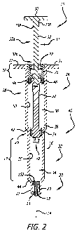
[0015] FIG. 2 is a cross-sectional view of the retractable safety syringe of
FIG. 1.
4
WO 2012/012784 CA 02806331 2013-01-22PCT/US2011/045117
[0016] FIG. 3 is a cross sectional perspective view of the distal end of the
retractable
safety syringe with an exploded view of a braking mechanism in accordance with
one non-
limiting embodiment.
[0017] FIGS. 4-6 are cross-sectional views of the retractable safety syringe
of FIG. 1
during various stages of operation.
[0018] FIG. 7 illustrates an enlarged view of a portion of FIG. 6.
[0019] FIG. 8 is a perspective view of a distal piston of a retractable safety
syringe in
accordance with on non-limiting embodiment.
[0020] FIG. 9 is a cross-sectional view of the distal piston of FIG. 8.
DETAILED DESCRIPTION OF EXAMPLE EMBODIMENTS
[0021] It will be appreciated that the terms "proximal" and "distal" may be
used throughout
the specification with reference to a medical professional or user utilizing a
syringe to deliver
medication to a patient. The term "proximal" refers to the portion of the
syringe closest to the
medical professional or user and the term "distal" refers to the portion
located furthest from
the medical professional or user. It will be further appreciated that for
conciseness and
clarity, spatial terms such as "vertical," "horizontal," "up," and "down" may
be used herein
with respect to the illustrated embodiments. However, syringes may be used in
many
orientations and positions, and these terms are not intended to be limiting
and absolute.
[0022] FIGS. 1-2 illustrate a retractable safety syringe 10 in accordance with
one non-
limiting embodiment. FIG. 1 is a side view of the retractable safety syringe
10. FIG. 2 is a
cross sectional view of the retractable safety syringe of FIG. 1 taken along
Line 2-2. The
retractable safety syringe 10 has a vacuum chamber 12 (FIG. 5) that creates a
retraction
force to retract a needle 14 of the retractable safety syringe 10 within the
retractable safety
syringe 10 so as to prevent accidental needle pricking and needle reuse.
Although the
discussion provided herein regarding the retractable safety syringe 10 is made
in relation to
small volume syringes (e.g.,about 1 cc or less), for which the example
embodiment is
particularly well-suited, it is also contemplated that the various aspects of
the retractable
safety syringe 10 may also be variously embodied and employed in safety
syringes having
larger volumes (e.g., 1 cc or more).
[0023] The retractable safety syringe 10 may have a syringe body 16 defining a
distal
portion 20, an intermediate portion 22, and a proximal portion 24. The
intermediate portion
22 may define a fluid chamber 34 fillable with fluidic medication. While the
example shown
is not a pre-filled syringe, it will be appreciate that alternative examples
may be provided for
5
WO 2012/012784 CA 02806331 2013-01-22 PCT/US2011/045117
use in a pre-filled syringe application. A needle holder 18 may be removably
engaged to the
distal portion 20 of the syringe body 16. A needle 14 may be fixedly engaged
to the needle
holder 18 and protrude coaxially out of the distal portion 20 of the syringe
body 16. The fluid
chamber 34 is in fluid communication with the needle 14 through the distal end
of the fluid
chamber 34. The retractable safety syringe 10 may also have a plunger assembly
37. The
plunger assembly 37 may also having a distal piston 26 and a proximal piston
28 disposed
along a rigid shaft 32. In various embodiments, the rigid shaft 32 may having
a plurality of
components assembled together to form the shaft. The proximal piston 26 may
have a
punch 70 distally protruding toward the needle holder 18. The plunger assembly
37 is
traversable within the syringe body 16 between a retracted position and an
engaged
position. Generally, the retracted position is when the distal piston 26 and
the proximal
piston 28 are closer to the proximal portion 24 of the syringe body 16 than
the distal portion
20 of the syringe body 16. But, the retracted position may include situations
when the distal
piston 26 does not contact the needle holder 18 and the distal piston 26 and
the proximal
piston 28 are closer to the distal portion 20 of the syringe body 16 than the
proximal portion
24 of the body 16. The engaged position is when the distal piston 26 is in
contact with the
needle holder 18 and engaged to the needle holder 18 (see FIG. 5). The rigid
shaft 32 may
extend out of the syringe body 16 through the proximal portion 24 of the
syringe body 16 and
may be coaxially aligned with the syringe body 16. A portion of the rigid
shaft 32 may also
extend between and couple the distal piston 26 and the proximal piston 28. A
thumb
platform 30 may be attached to the proximal portion of the rigid shaft 32. The
thumb
platform 30 may be operative to traverse the plunger assembly 37 between the
retracted
position and the engaged position. The retractable safety syringe 10 may also
finger
platforms 31 extending laterally from the proximal portion 24.
[0024] A wedge element 152 may be positioned between the needle holder 18 and
the
distal portion 20 to form an airtight and fluid tight seal therebetween. In
particular, the distal
portion 20 of the body 16 may have a cylindrical nub 21. The needle holder 18
may a
corresponding configuration as an inner surface 23 of the cylindrical nub 21.
The needle
holder 18 may have a lip 13 (see FIGS. 2 and 7) to engage the distal portion
20 such that
the needle holder 18 is not pushed out the distal portion 20 of the body 16 as
a wedge
element 152 is traversed to the releasing position (discussed below).
[0025] The retractable safety syringe 10 may also define an intermediate
chamber 36
positioned intermediate the distal piston 26 and the proximal piston 28. The
intermediate
chamber 36 may define a vent 38 allowing air to flow into the intermediate
chamber 36 and
flow out of the intermediate chamber 36, as discussed in more detail below.
While vent 38 is
6
WO 2012/012784 CA 02806331 2013-01-22 PCT/US2011/045117
illustrated as a bore, it is to be appreciated that the vent 38 may be a
variety of shapes and
may be located on the retractable safety syringe 10 in a variety of positions.
For example, in
some embodiments, the vent 38 may be a series of slits arranged around a
circumference of
the syringe body 16. In other embodiments, the vent 38 may be a bore that is
larger or small
in diameter than the illustrated embodiment. In various embodiments, the vent
38 may be
triangular, quadrangular (e.g., square, rectangle, rhomboidal), circular,
oval, or any
combination, for example. In any event, the vent 38 allows a pressure inside
the
intermediate chamber 36 to equalize to the pressure in a volume 40 external to
the
retractable safety syringe 10, e.g., the ambient air where the syringe is
used..
[0026] Still referring to FIGS. 1 and 2, the distal portion 20, the
intermediate portion 22,
and the proximal portion 24 may each have an elongate cylindrical
configuration, each
having an inner and an outer diameter. In the illustrated embodiment, the
outer diameters of
the various portions of the syringe body 16 may vary. For example, the outer
diameter of the
proximal portion 24 may be larger than the outer diameter of the intermediate
portion 22,
which is larger than the outer diameter of the distal portion 20. Similarly,
the inner diameters
of the various portions of the syringe body 16 may vary. For example, the
inner diameter of
the proximal portion 24 may be larger than the inner diameter of the
intermediate portion 22,
which is larger than the inner diameter of the distal portion 20. The syringe
body 16 may
have a proximal reducing portion 42 positioned intermediate the proximal
portion 24 and the
intermediate portion 22. The syringe body 16 may also have a distal reducing
portion 44
positioned intermediate the intermediate portion 22 and the distal portion 20.
By stepping
down the diameters of the various portions, the fluid chamber 34 may be
suitably sized to
receive and dispense small volumes of medication (e.g., less than 1 cc), while
the vacuum
chamber 12 is large enough to generate a sufficient retraction force. As is to
be appreciated,
in some embodiments, multiple portions of the syringe body 16 may have similar
inner
and/or outer diameters. For example, in one embodiment, the outer diameter of
the proximal
portion 24 is similar to the outer diameter of the intermediate portion 22.
Furthermore, while
the illustrated embodiments of the various portions of the retractable safety
syringe 10 are
cylindrical shapes having circular cross-sections, it is appreciated that the
various portions of
the retractable safety syringe 10 are not so limited. Instead, each of the
distal portion 20,
intermediate portion 22, and proximal portion 24 may each be any suitable
shape, where its
cross-section defines an oval, triangular, square, rectangular, pentagonal,
hexagonal, or any
other suitable bounded shape, such as a shape having multiple facets. In such
embodiments, the distal piston 26 and the proximal piston 28 may define a
corresponding
bounded shape. In one embodiment, for example, the distal portion 20 and
intermediate
7
WO 2012/012784 CA 02806331 2013-01-22 PCT/US2011/045117
portion 22 each have a circular cross-section, while the proximal portion 24
has an oval
cross-section.
[0027] Various portions of the body 16 may be transparent to allow viewing of
the fluidic
medication by the user. Furthermore, a marked portion 17 may also have volume
markings,
or other indicia, to indicate volume levels within the fluid chamber 34. The
aspect ratio (i.e.,
the ratio of the height to the width) of the fluid chamber 34 for any
particular retractable
safety syringe 10 may vary based on the intended volume of medication to be
dispensed.
For neonatal embodiments, for example, the aspect ratio of the fluid chamber
34 may be
configured to provide the proper resolution to dispense medication in
extremely small
dosages (e.g., less than 1 cc, or less than 0.5 cc). In other embodiments, the
aspect ratio of
the fluid chamber 34 may be configured to dispense medication in larger
dosages (e.g.,
more than 1 cc).
[0028] The proximal piston 28 may have an outer diameter similar to the inner
diameter of
the proximal portion 24. The proximal piston 28 may have a first seal 46 which
engages an
outer surface of the proximal piston 28 and an inner surface 50 of the
proximal portion 24. In
one embodiment, the first seal 46 is an o-ring. In other embodiments, the
first seal 46 may
be integral with the proximal piston 28, such as a molder wiper seal, for
example. The first
seal 44 may form an airtight seal between the proximal piston 28 and the inner
surface 50 of
the proximal portion 24. The first seal 44 may traverse along the inner
surface 50 of the
proximal portion 24 as the plunger assembly 37 is traversed between the
retracted position
and the engaged position.
[0029] The distal piston 26 may have an outer diameter similar to the inner
diameter of the
intermediate portion 22. The distal piston 26 may have a second seal 54 which
engages an
outer surface of the distal piston 26 and an inner surface 56 of the
intermediate portion 22.
The second seal 54 may form a watertight and an airtight seal between the
distal piston 26
and the inner surface 56 of the intermediate portion 22. The second seal 54
may traverse
along the inner surface 56 of the intermediate portion 22 as the plunger
assembly 37 is
traversed between the retracted position and the engaged position.
[0030] In various embodiments, the retractable safety syringe 10 may further
have a
braking mechanism 70 disposed at the proximal portion 24 that holds the
plunger assembly
37 in place at any position between the retracted position and a filling
position prior to
engagement of the distal piston 26 with the needle holder 18. The filling
position when the
plunger assembly 37 is between the engaged position and the retracted position
and the
distal piston 26 is closely adjacent the needle holder 18. By way of example
and not
8
WO 2012/012784 CA 02806331 2013-01-22 PCT/US2011/045117
limitation, the filling position may be when the distal piston 26 is in
contact with the needle
holder 18 but not engaged to the needle holder 18. FIG. 3 is a cross sectional
view of the
distal end of the retractable safety syringe 10 illustrating an exploded view
of the braking
mechanism 70 in accordance with one non-limiting embodiment. With reference to
FIGS. 2
and 3, the braking mechanism 70 permits the retractable safety syringe 10 to
be operated in
a substantially similar manner to prior art non-retracting conventional
syringes except that
the syringe 10 automatically retracts the needle 14 into the body 16
immediately after fluidic
medication has been injected into a patient or user. In prior art non-
retracting safety
syringes, the piston does not traverse back toward the retracted position when
thumb
pressure is released from the thumb platform. The reason is that prior art non-
retracting
safety syringes do not have a retraction force acting on the piston. In the
illustrated
embodiment, the plunger assembly 37 does not traverse back toward the
retracted position
when thumb pressure is released from the thumb platform 30 because of the
braking
mechanism 70. The braking mechanism 70 of retractable safety syringe 10
counteracts the
retraction force of the vacuum chamber 12 such that the needle 14 does not
automatically
retract when thumb pressure is released from a thumb platform 30.
[0031] The braking mechanism 70 may have a cover 72 and a brake member 74 that
are
engaged to an attachment base 76. The attachment base 76 may define an inner
that has a
stepped configuration. An upper step 78 may have a larger inner diameter
compared to an
inner diameter of a lower step 80. The upper step 78 and the lower step 80 may
be joined to
each other via a lip 82. The cover 72 may have an outer diameter sized to fit
the upper step
78. Also, a top surface 84 of the cover 72 may be flush with a top surface 86
of the
attachment base 76. The cover 72 may be fixedly attached to the attachment
base 76 via
sonic welding, adhesive and other joining methods known in the art. The
attachment base
76 may be fixedly attached to the proximal portion 24 using any suitable
joining technique
known in the art, such as spin welding, for example. The cover 72 may have a
through-hole
88 through which the shaft 32 may be disposed and slidingly traversed. An
inner surface 90
of the cover 72 may have an inner diameter that is smaller than the inner
diameter of the
lower step 80.
[0032] The brake member 74 may be disposed and frictionally engaged to the
cover 72.
The brake member 74 may be split into two or more pieces. In one embodiment,
the brake
member 74 is split into two pieces that are mirror configurations of each
other. When the
brake member 74 is disposed in the cover 72, an outer diameter of the brake
member 74
may be equal to or slightly greater than the inner diameter of the inner
surface 90 of the
cover 72. In this manner, the brake member 74 frictionally engages the cover
72 and the
9
WO 2012/012784 CA 02806331 2013-01-22PCT/US2011/045117
inner surface 90 of the cover 72 biases the brake member 74 inwardly toward
the shaft 32.
The amount of inward bias may be pre-set by changing the relative sizes of the
inner
diameter of the cover 72 and the outer diameter of the brake member 74.
[0033] The attachment base 76 may also house a shaft seal 92. The shaft seal
92 may
have a longitudinal flange 94 defining a through-hole 96 through which the
shaft 32 may be
disposed and slidingly traversed. The shaft seal 92 forms an airtight seal
with the shaft 32 in
order to maintain a vacuum in the vacuum chamber 12 when the proximal piston
28 is
traversed distally from the attachment base 76. The shaft 32 may have
different outer
diameters for different portions. For example, the shaft 32 may have a wide
portion 32a and
a narrow portion 32b. The longitudinal flange 94 of the shaft seal 92 may flex
to expand or
contract the through-hole 96 in order to maintain contact with the shaft 32.
Furthermore, as
the various portions of the shaft 32 is slidingly traversed past the brake
member 74, the
brake member will exert more breaking (e.g., frictional) force on the wide
portion 32a as
compared to the narrow portion 32b.
[0034] When the brake member 74 is disposed in the cover 72, the brake member
74 is in
a braking position. At the braking position, the brake member 74 may have a
plurality of
fingers or projections 100 that inwardly protrude toward the shaft 32. The
inner surface 88 of
the cover 72 biases the projections 100 inwardly, and the projections 100
press against the
outer surface of the shaft 32 inducing a frictional force between the
projections 100 of the
brake member 74 and the outer surface of the shaft 32. Alternatively, it is
also contemplated
that the brake member 74 may have a cylindrical inner surface. The entire
inner surface of
the brake member 74 may contact or press against the outer surface of the
shaft 32.
Accordingly, it is contemplated that the friction surface of the brake member
74 that presses
against the outer surface of the shaft 32 may have other configurations to
change the
amount of inward bias. It is also contemplated the amount of friction force
between the
brake member 74 and the outer surface of the shaft 32 may be varied to meet
the
requirements of the syringe. For example, the inner diameter of the inner
surface 90 of the
cover 72 may be reduced so as to further bias the projections 100 against the
outer surface
of the shaft 32. The friction force between the brake member 74 and the shaft
32 may also
be varied by changing the material of the brake member 74 and the shaft 32 or
having
different finishes at the interface of the outer surface of the shaft 32 and
the friction surface
of the brake member 74. During operation, when the brake member 74 is at the
braking
position (see FIGS. 2 and 4), the friction force between the projections 100
of the brake
member 74 and the shaft 32 is less than the friction force between the brake
member 74 and
the cover 72. In this manner, the brake member 74 is not dislodged out of the
cover 72 and
10
WO 2012/012784 CA 02806331 2013-01-22PCT/US2011/045117
within the lower step 80 (e.g., released position) as the plunger assembly 37
is traversed
toward the filling position or engaged position. The shaft 32 may slide
against the
projections 100 of the brake member 74 as the plunger assembly 37 is traversed
between
the retracted position and the engaged position without the brake member 74
being
dislodged from the braking position due to the frictional forces of the
projections 100 of the
brake member 74 and the shaft 32 being less than the frictional forces of the
brake member
74 and cover 72.
[0035] The brake member 74 is traversable between the braking position and a
released
position. When the brake member 74 is traversed to the released position (see
FIGS. 5-6),
the brake member 74 is disposed within the lower step 80 of the interior
cavity of the
attachment base 76. The inner surface 90 of the cover 72 no longer biases the
projections
100 inwardly to press the projections 100 of the brake member 74 against the
shaft 32
creating the frictional force that counteracts the retraction force of the
vacuum chamber 12.
At the released position, the brake member 74 is loose because the lower step
80 defines a
larger volume and the brake member 74 such that the brake member 74 falls
apart, or
otherwise expands, when disposed within the lower step 80. The projections 100
do not
press against the outer surface of the shaft 32 and does not produce any
counteracting
forces such that the plunger assembly 37 may be freely retracted toward the
retracted
position when the user releases the thumb platform 30.
[0036] To traverse the brake member 74 from the braking position to the
released position,
the plunger assembly 37 may be formed with a ram 106 which initially contacts
an upper
surface 109 (see FIG. 3) of the brake member 74 and pushes the brake member 74
out of
the cover 72 and within the lower step 80. More particularly, when the plunger
assembly 37
is traversed toward the engaged position, a lower surface 108 of the ram 106
contacts the
upper surface 109 of the brake member 74. As the plunger assembly 37 is
further traversed
to the engaged position, the ram 106 continues to push downwardly on the brake
member
74 urging the brake member 74 off of the inner surface 90 of the cover 72 and
within the
lower step 80. An outer diameter of the ram 106 may be smaller than an inner
diameter of
the through-hole 88 of the cover 72 such that there is no frictional
engagement between the
ram 106 and the cover 72. As shown in FIGS. 1-3, the ram 106 may be integrally
formed
with the shaft 32 and the thumb platform 30 such that the ram 106 is formed as
part of the
plunger assembly 37 in general. In some embodiments, the ram 106 may be formed
with
the thumb platform 30, and the thumb platform 30 may have a receiver portion
that receives
a proximal portion of the shaft 32.
11
WO 2012/012784 CA 02806331 2013-01-22PCT/US2011/045117
[0037] In use, the braking mechanism 74 prevents the plunger assembly 37 from
retracting
toward the retracted position during operation of the syringe as long as the
brake member 74
is maintained at the braking position. The user may release the thumb platform
30 without
any concern that the plunger assembly 37 will be traversed back toward the
retracted
position. In some embodiments, various techniques may be used to regulate the
translation
of the plunger assembly, such as the techniques disclosed in concurrently
filed application
attorney number 1958469.00018, application serial number 12/842,884 entitled
"RETRACTABLE SAFETY SYRINGE WITH NON-LOADED SEAL" and filed July 23, 2010,
the entire disclosure of which is expressly incorporated herein by reference.
[0038] Referring now to FIGS. 2-7, the retractable safety syringe 10 may be
shipped and
ultimately provided to a medical professional or user with the plunger
assembly 37 in a
retracted position (see FIG. 2) without fluidic medication contained within
the variable fluid
chamber 34. In the retracted position, the narrow portion 32b of the shaft 32
is proximate
the shaft seal 92 and there is little or no vacuum in the vacuum chamber 12.
Accordingly,
there is essentially no load pressure on the various seals. The user may then
distally
traverse the plunger assembly 37 into the filling position. In the filling
position, the brake
member 74 remains in frictional contact with the inner surface 90 of the cover
72 and the
wedge element 152 remains in frictional contact with the needle holder 18.
[0039] The vacuum chamber 12 is enlarged upon movement of the plunger assembly
37
toward the distal portion 20 such that the internal volume of the vacuum
chamber 12 is
increased. Since the vacuum chamber is sealed, the vacuum created within the
vacuum
chamber 12 may exert a retraction force upon the plunger assembly 37. As will
be
understood by one of skill, the retraction force may be exerted upon the shaft
32 indirectly
via exertion upon the proximal surface of the proximal piston 28. The
retraction force may
vary as the plunger assembly 37 moves toward the distal portion 20 or toward
the proximal
portion 24. Thus, the retraction force may increase or decrease, respectively.
The retraction
force may be exerted on the plunger assembly 37 directed from the distal
portion 20 toward
the proximal portion 24. The retraction force may be caused due to a vacuum
pressure in
the vacuum chamber 12.
[0040] The intermediate chamber 36 is bounded distally by the distal piston 26
and
proximally by the proximal piston 28. FIGS. 2, 4, and 5 illustrate the
intermediate chamber
36 during various stages of operation, in accordance with one non-limiting
embodiment.
FIG. 2 illustrates when the intermediate chamber is 36 bounded by the proximal
portion 24.
FIG. 4 illustrates the intermediate chamber 36 being partially bounded by the
proximal
12
WO 2012/012784 CA 02806331 2013-01-22
PCT/US2011/045117
portion 24 and partially bounded by the intermediate portion 22. FIG. 5
illustrates when the
intermediate chamber 36 bounded by the intermediate portion 22. In the
illustrated
embodiment, the inner diameter of the proximal portion 24 is larger than the
inner diameter
of the intermediate portion 22. As the plunger assembly 37 is moved toward the
distal
portion 20, the intermediate chamber 36 may decrease in volume. As the volume
of the
intermediate chamber 36 decreases, air from the intermediate chamber is
expelled through
the vent 38 in order to avoid a build-up of internal pressure. Conversely, as
the plunger
assembly 37 is moved toward the proximal portion 24, the intermediate chamber
36 may
increase in volume. As the volume of the intermediate chamber 36 increases,
air from a
volume 40 external the intermediate chamber 34 is admitted through the vent 38
in order to
avoid the creation of vacuum pressure.
[0041] When the retractable safety syringe 10 is in the filling position, the
needle 14 may
be inserted into a medication container containing fluidic medication. The
medical
professional or user may slip his or her fingers underneath the thumb platform
30 and pull
the thumb platform 30 away from the syringe body 16. Note that even though the
vacuum
chamber 12 is exerting a vacuum force on the proximal piston 28 when the
retractable safety
syringe 10 is in the filling position, the force exerted by the brake member
74 on the shaft 32
exceeds the vacuum force. As the plunger assembly 37 is traversed toward the
retracted
position, the fluid within the medication container is transferred into the
fluid chamber 34 via
the needle 14. When the appropriate amount of fluidic medication is filled in
the variable
fluid chamber 34, the user stops traversing the thumb platform 30 away from
the syringe
body 16. The user or medical professional removes the needle 14 from the
medication
container. A small amount of air may be trapped within the variable fluid
chamber 34. To
remove the trapped air, the user or medical professional may invert the
retractable safety
syringe 10 such that the needle 14 is pointed upwardly. The user or medical
professional
taps the outside surface of the syringe body 16 to urge the trapped air within
the fluid
chamber 34 toward the needle tip. The medical professional or user may place
his or her
first and second fingers underneath the finger platforms 31 and place his or
her thumb on
the thumb platform 30. When the thumb platform 30 is depressed to remove the
trapped air
within the variable fluid chamber 34, a retraction force is created by the
vacuum chamber 12
when the plunger assembly 37 is traversed toward the engaged position to
remove trapped
air within the variable fluid chamber 34. The force exerted by the brake
member 74 on the
shaft 32 exceeds the retraction force, thereby allowing the medical
professional or user to
remove their thumb from the thumb platform 30, if necessary.
13
WO 2012/012784 CA 02806331 2013-01-22PCT/US2011/045117
[0042] At this moment, the retractable safety syringe 10 has been prepared to
inject the
fluidic medication into a patient. The needle 14 is inserted into the patient
and the plunger
assembly 37 is traversed from the retracted position to the engaged position.
The user or
medical professional traverses the plunger assembly 37 from the retracted
position to the
engaged position by placing his or her first and second fingers under the
finger platforms 31
and his or her thumb on the thumb platform 30. As the vacuum chamber 12 is
enlarged it
produces a retraction force which urges the plunger assembly toward the
retracted position.
When the plunger assembly 37 is traversed to the engaged position, the distal
piston 26 may
engage the needle holder 18 and needle 14 (see FIG. 5). As the plunger
assembly 37 is
traversed to the engaged position, the ram 106 contacts the brake member 74
and pushes
the brake member 74 out of the cover 72 and within the lower step 80 (see FIG.
3). With the
brake member 74 pushed from the cover 72, the brake member no longer applies a
braking
force to the shaft 32.
[0043] Once the distal piston 26 engages the needle holder 18 and needle 14,
the user or
medical professional may release pressure on the thumb platform 30 such that
the retraction
force is greater than the thumb pressure and the plunger assembly 37 is urged
back toward
the retracted position (see FIG. 6). The needle holder 18 and needle 14 are
urged back into
the intermediate portion 22 of the syringe body 16 thereby covering the needle
14 and
preventing accidental needle prickings and needle reuse. Also, the needle 14
may be
canted toward one side of the syringe body 16. Canting the needle 14 toward
one side of
the syringe body 16 keeps the needle 14 from accidentally protruding through
the distal end
of the syringe body 16.
[0044] The distal piston 26 may be engageable to the needle holder 18 and
needle 14 via
any method known in the art. By way of example and not limitation, the distal
piston 26 may
be engageable to the needle holder 18 and needle 14 via the structure
disclosed in U.S. Pat.
No. 6,413,236, the entire content of which is expressly incorporated herein by
reference.
[0045] FIG. 7 is an enlarged view of a portion of FIG. 6. FIG. 8 is a
perspective view of the
distal piston 26 in accordance with one non-limiting embodiment. FIG. 9 is a
perspective
view of the distal piston 26 of FIG. 8 taken along a longitudinal axis
(illustrated as "A").
Referring now to FIGS. 7-9, by way of example and not limitation, the proximal
portion of the
needle holder 18 may have a step 19. The step 19 may be joined to a distal
portion of the
needle holder 18 via a lip 21. When the needle holder 18 is engaged to the
distal portion 20,
the wedge element 152 may be in frictional contact with the step 19 of the
needle holder 18
(see FIG. 4). The distal piston 26 may have a punch 70 distally protruding
toward the needle
14
WO 2012/012784 CA 02806331 2013-01-22PCT/US2011/045117
holder 18. The punch 70 may be a substantially hollow cylinder. In one
embodiment the
punch 70 is equipped with an upper proximal block tab 73 extending around less
than about
one-half of the circumference of the substantially hollow cylinder, and a
lower distal wedge
tab 75 extending around less than about one-half of the circumference of the
substantially
hollow cylinder and located opposite the upper block tab 73. During the
engagement
process, the punch 70 may distally push the wedge element 152 (see FIG. 5) and
engage
the needle holder 18, and more particularly, the lip 21 of the needle holder
18. The lower
distal wedge tab 75 passes and hooks onto the lip 21 of the needle holder 18
when the
plunger assembly 37 is traversed to the engaged position, as shown in FIG. 7.
After
engagement, the needle body 18 and needle 14 are withdrawn into the syringe
body 16 via
the retraction force. The punch 70 may also define a cutout 71 positioned
longitudinally
proximal to upper proximal block tab 73 and a ramp 77 (see FIG. 9) positioned
longitudinally
proximal to lower distal wedge tab 75. When the needle body 18 and the needle
14 are
retracted, the ramp 77 may laterally bias the step 19 of the needle body 18
and the cutout 71
may receive a portion of the step 19 of the needle body 18 to cant (see FIG.
7) the needle 16
toward one side of the syringe body 16.
[0046] The above description is given by way of example, and not limitation.
Given the
above disclosure, one skilled in the art could devise variations that are
within the scope and
spirit of the invention disclosed herein. Further, the various features of the
embodiments
disclosed herein can be used alone, or in varying combinations with each other
and are not
intended to be limited to the specific combination described herein. Thus, the
scope of the
claims is not to be limited by the illustrated embodiments.
15