Note: Descriptions are shown in the official language in which they were submitted.
CA 02806703 2014-06-06
FRICTION CORE BRAKE
BACKGROUND OF THE INVENTION
[0003] This disclosure relates to a media cartridge for a
printer. In particular, this disclosure relates to
improvements in the feeding of media from the media
cartridge.
[0004] Many printers are designed to receive cartridges
that provide a length of media for printing. Typically, the
length of media is wrapped around a core and then fed from
the inside of the cartridge during the printing process.
[0005] A cartridge of this kind is usually initially
stored and transported separate from the printer itself.
During the handling of the cartridge, the cartridge may be
subject to vibration and various other types of motion that
could result in the internal movement of the various parts
of the cartridge, including the media.
[0006] It has been found that in many cartridges with
rolls of media, the media may have a tendency to unwrap
itself from the roll. This makes logical sense as a tightly
wrapped roll will have a tendency to unravel to reach a
lower energy state and a state of greater disorder or
entropy.
[0007] However, this type of unraveling prior to or
during use of the cartridge presents a number of problems.
Specifically, if the media unrolls within the cartridge,
then the media can pack itself against the side walls of the
cavity. When this happens, any back feeding of the end of
the media onto the roll is compromised, as there is no space
in the internal cavity. As there is no space for the media
to retract, this may result in bunching or jamming of the
media along the media path or in the printing mechanism.
- 1 -
CA 02806703 2013-01-25
WO 2012/015537 PCT/US2011/039795
[0008] Hence, a need exists for an improved media
cartridge. In particular, there is a need for a media
cartridge with improved control of the media within the
cartridge housing.
SUMMARY OF THE INVENTION
[00093 A cartridge assembly is disclosed. The cartridge
assembly includes a core, a cartridge housing defining a
cavity that receives the core, a shaft extending from the
cartridge housing into the cavity and at least part way into
the core, and a torsion spring. The torsion spring is
helically wound to define a coiled outer surface that is
received in the core. The torsion spring also includes at
least one end that engages the shaft. When the core is
rotated in a first direction about the shaft, a
circumference of the coiled outer surface of the torsion
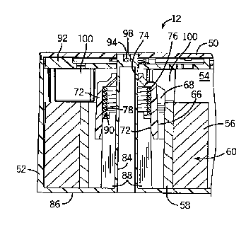
spring increases thereby restricting a rotation of the core
in the first direction. When the core is rotated in a
second direction opposite the first direction, the coiled
outer surface provides a controlled amount of drag to resist
a rotation of the core in the second direction.
[0010] In some forms, a length of media may be wrapped
around the core thereby forming a roll of media. An outer
diameter of the length of media on the roll of media may be
substantially prevented from expanding by rotation of the
core in the first direction. By preventing the expansion of
the roll of media, a back-feeding of a portion of a free end
of the roll of media back into the cavity may be allowed
without causing jamming along a media path of the cartridge
assembly.
[0011] In other forms, the shaft may be integrally formed
with a base wall of the cartridge housing. The shaft may
include at least one rib formed therein that engages the end
of the torsion spring. The end of the torsion spring may be
bent radially inward to engage the shaft or its at least one
rib.
- 2 -
CA 02806703 2013-01-25
WO 2012/015537 PCT/US2011/039795
[0012] In still other forms, the cartridge assembly may
include a core holder located intermediate the core and the
torsion spring. The core and the core holder may have an
interference fit therebetween, such that the core rotates
with the core holder. The core holder may include a
plurality of radially-outward extending prongs that engage
an inner diameter of the core to form the interference fit.
In this form, the core holder may receive the torsion spring
in an axially-extending through hole of the core holder.
The torsion spring may form an interference fit with the
core holder.
[0013] In this form, the core holder may include an upper
portion and a lower portion. The upper portion may have an
inner diameter of the through hole that is sized to
correspond to an outer diameter of the shaft (for bearing on
one another or the like). The lower portion may have a
inner diameter of the through hole that is sized to provide
an interference fit with the torsion spring. The through
hole of the core holder may include an axially-facing stop
in the through hole between the upper portion and the lower
portion of the core holder. A top end of the torsion spring
may abut this axially-facing stop in the core holder,
thereby positioning the torsion spring within the through
hole of the core holder. Further, the shaft may include
ribs with an upward-facing step formed in the ribs. The
upward-facing step on the ribs may prevent the torsion
spring from falling out of a bottom of the core holder when
the core holder and torsion spring are received over the
shaft.
[0014] In one form, the torsion spring may be inserted
directly into the core so as to form an interference fit
between the torsion spring and the core.
[0015] In another form yet, the cartridge assembly may
further include a media pinch arm that restricts a free end
of the media from moving, when the media pinch arm is
- 3 -
CA 02806703 2013-01-25
WO 2012/015537
PCT/US2011/039795
engaged.
[0016] Accordingly, the disclosed media cartridge
provides a friction core brake. The friction core brake
prevents the core/core holder from rotating in a direction
that would accommodate the unraveling of the media from the
roll and result in the packing of the media around the outer
edge of the internal cavity of the cartridge. While
providing this anti-unwinding functionality, the friction
core brake also permits a core/core holder to rotate in one
direction under controlled drag during the feeding of the
media.
[0017] As the friction core brake prevents the
substantial expansion of the roll diameter within the
cartridge, the likelihood of media jamming during the back
feeding of the media into an internal cavity of the
cartridge is minimized.
[0018] These and still other advantages of the invention
will be apparent from the detailed description and drawings.
What follows is merely a description of a preferred
embodiment of the present invention. To assess the full
scope of the invention, the claims should be looked to as
the preferred embodiment is not intended to be the only
embodiment within the scope of the claims.
BRIEF DESCRIPTION OF THE DRAWINGS
[0019] FIG. 1 is a perspective view of a printer;
[0020] FIG. 2 is a perspective view of the printer with a
media cartridge exploded therefrom;
[0021] FIG. 3 is a perspective view of a printer with the
media cartridge inserted or loaded therein;
[0022] FIG. 4 is a top front side perspective view of the
media cartridge of FIGS. 2 and 3 apart from the printer;
[0023] FIG. 5 is a bottom rear side perspective view of
the media cartridge;
[0024] FIG. 6 is a top plan view of the media cartridge
with the top portion of the housing removed;
- 4 -
CA 02806703 2013-01-25
WO 2012/015537 PCT/US2011/039795
[0025] FIG. 7 is a bottom plan view of the media
cartridge;
[0026] FIG. 8 is a cross-sectional view taken through
line 8-8 of FIG. 4 showing a length of media, and an ink
ribbon, and a corresponding edge protector of the media
cartridge;
[0027] FIG. 9 is an exploded view of the media cartridge;
[0028] FIG. 10 is a cross-sectional side view taken
through line 10-10 of FIG. 4 showing a core holder assembly;
[0029] FIG. 11 is a cross-sectional top view taken
through the core holder assembly;
[0030] FIG. 12 is a top view of the media cartridge at an
initial point of insertion into the cartridge receptacle;
[0031] FIG. 13 is a top view of the media cartridge fully
inserted into the cartridge receptacle;
[0032] FIG. 14 is a cross-sectional side view taken
through line 14-14 of FIG. 12, illustrating a first point of
insertion of the media cartridge into the cartridge
receptacle, at which point the length of media and the ink
ribbon are centered between the print head and the platen
roller;
[0033] FIG. 15 is a cross-sectional side view showing
further insertion to a point at which the tab on the media
cartridge has reached the top of a slot in the cartridge
receptacle, but prior to the engagement of the angled ribs
on the other side of the media cartridge with the opposing
wall of the cartridge receptacle to bias the media and the
ink ribbon toward the print head;
[0034] FIG. 16 is a cross-sectional side view at still a
further point of insertion in which the angled ribs have
biased the media and the ink ribbon toward the print head;
[0035] FIG. 17 is a cross-sectional side view taken
through line 17-17 of FIG. 13 of a point of full insertion
of the media cartridge into the cartridge receptacle;
[0036] FIG. 18 is a detailed perspective view of the
- 5 -
CA 02806703 2013-01-25
WO 2012/015537
PCT/US2011/039795
ribbon lock member of the cartridge housing with the ink
ribbon spools removed;
[0037] FIG. 19 is a view similar to FIG. 18, but also
including the ink ribbon spools;
[0038] FIG. 20 is a bottom view showing the un-flexed
ribbon lock member engaging the teeth of the ink ribbon
spools;
[00393 FIG. 21 is a detailed perspective view of a
portion of the cartridge receptacle illustrating the
unlocking post and the ribbon drive spindles;
[00403 FIG. 22 is a cross-sectional side view taken
during the insertion of the media cartridge into the
cartridge receptacle just prior to the unlocking post
engaging the ribbon lock member;
(0041] FIG. 23 is a cross-sectional side view similar to
FIG. 22, but at a point of initial engagement between the
angled surface of the ribbon lock member and the angled
surface of the unlocking post; and
[0042] FIG. 24 is a cross-sectional side view after the
full insertion of the media cartridge into the cartridge
receptacle in which the unlocking post has flexed the ribbon
lock element outward to unlock the ink ribbon spools.
DETAILED DESCRIPTION OF THE PREFERRED EMBODIMENT
0043] Referring first to FIG. 1, a printer 10 is shown.
The printer 10 is of a type that is a portable handheld
printer for use at any of a number of locations and can also
be placed on a table top for stationary use. In FIGS. 2 and
3, the printer 10 is shown receiving a media cartridge 12 in
a cartridge receptacle 14 of the printer 10. Those having
ordinary skill in the art will appreciate that although the
printer 10 is shown as being a particular kind of printer,
that the features described herein with respect to the media
cartridge 12 and the printer 10 are applicable to any number
of kinds of cartridge-receiving printers.
- 6 -
CA 02806703 2013-01-25
WO 2012/015537 PCT/US2011/039795
[0044] The printer 10 of FIG. 1 includes a body 16 with a
head 18 located at one end thereof. The body 16 supports a
number of items including a keypad 20 for the entry of data,
a display 22 positioned between the keypad 20 and the head
18 of the printer 10, a row of buttons 24 on one lateral
side of the display 22, and a navigational keypad 26 on the
other lateral side of display 22. The display 22 is used to
display information related to the operation of the printer
such as a user interface or a text string as it is
entered by the user. The keypad 20, the row of buttons 24,
and the navigational keypad 26 are all used for user entry
of data into and/or control of the printer 10. Some of
these controls may be dedicated to performing certain
functions. For example, the row of buttons 24 may be used
to select an item on a corresponding list of items displayed
on the display 22 or may toggle the printer 10 between
various operational modes.
[00453 The head 18 of the printer 10 includes a cover 28
which may be lifted or removed to provide access to the
cartridge receptacle 14. As mentioned above, the cartridge
receptacle 14 is configured to receive the media cartridge
12 and, accordingly, the cartridge receptacle 14 includes a
number of printing and feeding components. Looking at FIG.
2 in which the media cartridge 12 is shown removed from the
printer 10, the components in and around the cartridge
receptacle 14 are clearly visible.
[0046] The cartridge receptacle 14 has a base wall 30
with generally perpendicular vertical walls 32 extending
upwardly from the base wall 30. The vertical walls 32 have
a shape which generally corresponds to the shape of the
media cartridge 12. Of course, as the media cartridge 12
fits within the cartridge receptacle 14, the vertical walls
32 have a form slightly larger than the form of the media
cartridge 12. This allows for the insertion of the media
- 7 -
CA 006703 2013-01-25 2012/015537
PCT/US2011/039795
cartridge 12 in the cartridge receptacle 14 with some
additional room for clearance.
[0047] A number of printer components are located in or
about the cartridge receptacle 14 that will, in some way,
interact with the media cartridge 12 upon the insertion of
the media cartridge 12 into the cartridge receptacle 14.
Extending upwardly from the base wall 30 there are various
components including a thermal print head 34, ribbon drive
spindles 36, and a deflection or unlocking post 38.
Although not present in the form shown, in some printers,
additional spindles may be present in the cartridge
receptacle 14 that engage a roll of media to assist in the
feeding of the media from the media cartridge.
[0048] On the vertical wall 32 of the cartridge
receptacle 14 on the end proximate the body 16, an opening
40 is formed through which a platen roller 42 may be
actuated. When no media cartridge 12 is in the cartridge
receptacle 14, the platen roller 42 is retracted and spaced
from the thermal print head 34 (as shown in FIG. 2). This
spacing allows for easier insertion of the media and ink
ribbon of the media cartridge 12 between platen roller 42
and the thermal print head 34 during the loading of the
media cartridge 12 into the cartridge receptacle 14. Then,
either during or after loading, the platen roller 42 is
actuated towards the thermal print head 34 to establish a
print line. In some printer constructions, the actuation of
the platen roller 42 toward or away from the thermal print
head 34 may be linked, mechanically or otherwise, to the
insertion of the media cartridge 12 into the cartridge
receptacle 14. During printing, the platen roller 42 will
provide pressure along the print line such that, when the
thermal print head 34 is heated, ink on the ink ribbon will
be transferred to the print media.
[0049] A media exit 44 is found on the lateral side of
printer 10, just past the thermal print head 34 and the
- 8 -
CA 02806703 2013-01-25
WO 2012/015537
PCT/US2011/039795
platen roller 42. After the media is printed on, the media
will be directed through this media exit 44 and to the
exterior of the printer 10.
[0050] A depressible lever 46 is positioned proximate the
media exit 44 on the exterior of the printer 10. This
depressible lever 46 is linked to a cutting mechanism (not
shown in detail) at the media exit 44. After a printer 10
has printed on a length of media, the printed media is
directed through the media exit 44. At this point, the
depressible lever 46 may be used to actuate the cutting
mechanism so that the printed portion of the media is
severed.
[0051] Now with additional reference to FIGS. 4 through
11, the media cartridge 12 is shown separate from the
printer 10. The media cartridge 12 includes a housing 48
including a top housing portion 50 and a bottom housing
portion 52 which are joined to form an internal cavity 54.
As best illustrated in FIG. 9, in which the media cartridge
12 is shown in an exploded form, the internal cavity 54 of
media cartridge 12 houses various components.
[0052] The various components housed in the internal
cavity 54 of the housing 48 include a length of media 56
wrapped around a tubular central core 58 that forms a roll
of media 60 with a free end 62 extending therefrom. The
length of media 56 may be any of various kinds of media
including, for example, paper, adhesive labels, and so
forth. In some forms, the length of media 56 may be a
continuous unbroken length that can be cut using a
guillotine cutter or the like at the media exit 44 of the
printer 10. In other forms, there may be perforations
formed along the length of media 56 so that, after printing,
the printed portion of the media may be separated from the
length of media 56. It will be appreciated that while the
length of media 56 is shown in the form of a roll, that the
- 9 -
CA 02806703 2013-01-25
WO 2012/015537
PCT/US2011/039795
length of media 56 might be otherwise arranged within the
media cartridge 12 for dispensing.
[0053] This roll of media 60 is axially received on a
core holder 64. The core holder 64 has a radially-outward
facing surface 66 with three radially-extending prongs 68.
The three radially extending prongs 68 are sized such that
when the core 58 of the roll of media 60 is axially inserted
onto the core holder 64, the prongs 68 have an interference
fit with the core 58 (as best illustrated in FIG. 11).
Accordingly, the core holder 64 rotates with the core 58 of
the roll of media 60. The core holder 64 has also an
axially-extending through hole 70 with a lower portion 72
which is of a first diameter and an upper portion 74 which
is of a second diameter that is less than the first
diameter. At the transition between the lower portion 72
and the upper portion 74, the core holder 64 necks down
thereby providing an axially-facing stop 76.
[0054] A helically wound torsion spring 78 is received
from the bottom side of the lower portion 72 of the core
holder 64 and is inserted until a top end of the torsion
spring 78 abuts the axially-facing stop 76. The torsion
spring 78 has a diameter which is slightly larger than the
diameter of the lower portion 72 of the core holder 64, such
that upon insertion of the torsion spring 78 into the core
holder 64, a slight interference fit occurs between the
torsion spring 78 in an unstressed state and the core holder
64. Two ends 80 and 82 of the torsion spring 78 are bent
radially inward towards the rotational axis of the roll of
media 60.
[0055] The subassembly of the roll of media 60, the core
holder 64, and the torsion spring 78 are received on a shaft
84 that extends upwardly from a floor 86 of the bottom
housing portion 52. As best seen in FIGS. 10 and 11, this
shaft 84 has four radially-outward extending ribs 88 or fins
that run longitudinally along the shaft 84. A upward-facing
- 10 -
CA 02806703 2013-01-25
WO 2012/015537 PCT/US2011/039795
step 90 is formed in each of the ribs 88 such that the
portion of the rib 88 closer to the floor 86 extends
radially further from the shaft 84 than the portion of the
rib 88 further from the floor 86.
[0056] As best illustrated in FIG. 10, when the core
holder 64 is axially received on the shaft 84, the radii of
the upper and lower portions of the ribs 88 and the upward-
facing step 90 between the portions of the ribs 88 are
located such that the upward-facing step 90 assists in
retaining the lower end of the torsion spring 78 within the
through hole 70 of the core holder 64. The upper portion 74
of the core holder 64 has an inner circumference that is
sized to slide over and bear on the outer circumference of
the shaft 84 during the rotation of the core holder 64
around to the shaft 84. Furthermore, as best illustrated in
FIG. 11, the upper portions of the ribs 88 and the lower
bent-in end 80 of the torsion spring 78 are arranged such
that, if the torsion spring 78 is rotated about its axis,
the lower bent-in end 80 will contact a side of the upper
portion of one of the ribs 88.
[0057] With reference to the top-view of the media
cartridge 12 in FIG. 11, during the feeding of the length of
media 56 from the roll of media 60, the roll of media 60
will rotate counter-clockwise. However, because the length
of media 56 is wrapped around the core 58 when at rest,
there is a tendency for the roll of media 60 to want to spin
in the opposite direction, thereby unraveling the length of
media 56 from the core 58. If this unraveling occurs, the
length of media 56 will remain wound but, to reach a lower
energy state, will loosen itself in the area around the core
58 while simultaneously causing the outer diameter of the
roll to expand such that the length of media 56 packs itself
against the inner walls of the housing 48.
[0058] This expansion of the roll diameter and packing
against the walls is problematic. As the outermost portion
- 11 -
CA 006703 2013-01-25 2012/015537
PCT/US2011/039795
of an internally unwound expanded roll of media would engage
the inner walls of the housing 48, any attempt to back feed
the length of media 56 would result in the frictional
engagement of the roll of media 60 and the inner walls of
the housing 48 and provide no room in the chamber for
retraction. As this back feeding is essentially trying to
add additional media length to the roll of media 60, but the
internally unwound expanded roll of media has already
occupied expanded to contact the inner walls of the housing
48, there would be nowhere for the back fed portion of the
length of media to go. Thus, back feeding in such a
condition is likely to result in jamming and bunching of the
length of media 56 along the media path.
[0059] The torsion spring 78 serves as a clutch or a
friction brake that prevents this kind of unraveling of the
length of media 56 from the roll of media 60. The torsion
spring 78 is wound to have a coiled outer surface which has
a diameter that is slightly greater than the diameter of the
lower portion 72 of the through hole 70 of the core holder
64. Upon initial rotation of the core holder 64, the
torsion spring 78 rotates with the core holder 64 due to
this interference fit between the torsion spring 78 and the
core holder 64. At some point along the path of rotation,
the lower bent-in end 80 contacts one of the upper portions
of the ribs 88. What happens after engagement of the lower
bent-in end 80 with the rib 88 will depend on the direction
of rotation and the direction of winding of the torsion
spring 78.
[0060] If the roll of media 60 is rotating counter-
clockwise (from the top perspective of FIG. 11) when the
lower bent-in end 80 of the torsion spring 78 engages the
rib 88, then this engagement should induce a stress in the
torsion spring 78 that will cause the diameter of the
torsion spring 78 to decrease slightly (while still
maintaining an interference fit with the core holder 64)
- 12 -
CA 006703 2013-01-25 2012/015537 PCT/US2011/039795
such that the roll of media 60 can continue to rotate
counter-clockwise, albeit under a controlled drag. The
amount of drag should be sufficiently small, such that the
length of media 56 does not tear during forward feeding and
such that the feed mechanism will be able to provide
sufficient power to continue with the forward feeding of the
length of media 56.
[0061] If the core 58 of roll of media 60 is rotating
clockwise (from the top perspective of FIG. 11), then this
would likely be due to an unraveling force as described
above. In this direction, the lower bent-in end 80 of the
torsion spring 78 engages the rib 88, but the induced stress
in the torsion spring 78 will cause the diameter of the
torsion spring 78 to expand. As the diameter expands, the
interference fit between the torsion spring 78 and the core
holder 64 becomes tighter and the increased friction between
the two prevents further rotation of the core holder 64 in
the clockwise direction.
[0062] Thus, in the media cartridge 12, the torsion
spring 78 is configured to allow the core holder 64 (and the
core 58 which is connected thereto) to rotate in one
direction under a controlled drag while inhibiting the
substantial rotation of the core holder 64 in the opposite
direction.
[0063] The materials of the core holder 64 and the
torsion spring 78 should be selected with this function in
mind. In one preferred form, the core holder 64 is made of
an acetal or nylon material and the torsion spring 78 is
made of a music wire for excellent wear control and drag
consistency.
[0064] It should be appreciated that in some forms of the
media cartridge 12, the core holder 64 might be eliminated
as an intermediate element. In this form, the torsion
spring 78 may be directly inserted into the core 58 with the
components sized to achieve an interference fit similar to
- 13 -
CA 02806703 2013-01-25
WO 2012/015537 PCT/US2011/039795
that described above with respect to the torsion spring 78
and the core holder 64. In this case, the frictional brake
or rotational clutch will largely work the same as is
described above, but it will be the interface between the
core 58 and the torsion spring 78 (as opposed to between the
core holder 64 and the torsion spring 78) that provides
either the controlled drag or the frictional locking upon
rotation.
[0065] Returning now to the general structure of the
media cartridge 12, the media cartridge 12 also includes a
media clutch plate 92. The media clutch plate 92 is located
adjacent to the roll of media 60, is received on the top end
of the shaft 84 of the bottom housing portion 52, and is
rotatable about the shaft 84. On the top side of the media
clutch plate 92, a biasing spring wire 94 is run between two
engagement elements 96 formed in the top side of the media
clutch plate 92. The biasing spring wire 94 snakes in a
mirrored S-shape near the top of the shaft 84 and has a
portion which runs through a slit 98 on the top of the shaft
84. Because of the manner in which the media clutch plate
92 is arranged in the media cartridge 12, the biasing spring
wire 94 will tend to bias the media clutch plate 92 in a
clockwise direction (as viewed from the top). On a bottom
side of the media clutch plate 92, a number of spacers 100
are formed which axially space the media clutch plate 92
from the roll of media 60. On the outer periphery of the
media clutch plate 92, there is an outwardly-extending tab
102 which engages a wall of the printer 10 during insertion
as well as a media pinch arm 104. The media pinch arm 104
is spaced from, but extends parallel to, the axis of
rotation of the media clutch plate 92 and the roll of media
60. A cylindrical sheath 106 is located on the media pinch
arm 104.
[0066] When the media cartridge 12 is removed from the
printer 10 for transportation or the like, the biasing
- 14 -
CA028067032013-01-25
WO 2012/015537
PCT/US2011/039795
spring wire 94 biases this media clutch plate 92 clockwise
(as viewed from the top of the media cartridge 12) toward a
pinch position (not shown) in which the cylindrical sheath
106 on the media pinch arm 104 pinches the free end 62 of
the length of media 56 between the sheath 106 and an inner
wall 108 of the housing 48. This prevents the free end 62
of the length of media 56 from retracting back into the
internal cavity 54 of the housing 48.
[0067] When the media cartridge 12 is inserted into the
printer 10, the tab 102 engages a wall of the printer 10 and
is rotated counter-clockwise (again, as viewed from the
top). This movement of the tab 102 causes the rotation of
the media clutch plate 92 against the biasing force of the
biasing spring wire 94 to an un-pinched position, as shown
in FIG. 11, in which the media pinch arm 104 disengages the
free end 62 of the length of media 56 such that the free end
62 can be fed through the printer 10. It should be noted
that the movement to the un-pinched position will likely
occur just after a nip point is formed along the media path
during the loading process of the media cartridge 12 into
the printer 10 so that the free end 62 of the length of
media 56 is prevented at all times from retracting
irretrievably into the internal cavity 54.
[0068] In view of that which has already been described,
and with particular reference to FIG. 6, the internal cavity
54 is roughly divided into two sections. The first section
of the internal cavity 54 has been described above. This
first section is primarily devoted to housing the roll of
media 60 and related components (i.e., the media clutch
plate 92, the frictional core brake 64, etc.) for
controlling the manner in which the length of media 56 is
fed. The other section of the internal cavity 54 is devoted
to housing two ink ribbon spools 110 and 112 that carry an
ink ribbon 114, which will be described in more detail
below. These two sections are arranged such that they
- 15 -
CA 006703 2013-01-25 2012/015537 PCT/US2011/039795
generally bifurcate the media cartridge 12 into two sides,
with the roll of media 60 on one side (the right side in
FIG. 6) and the two spools 110 and 112 that carry the ink
ribbon 114 on the other side (the left side in FIG. 6).
[0069] On the side of the media cartridge 12 with the two
spools 110 and 112 that support the ink ribbon 114, an open
space 116 extends through the cartridge housing 48 which
receives the thermal print head 34 during the loading of the
printer 10. On the side of the open space 116 opposite
which the two spools 110 and 112 are housed, there is a
media path which is generally denoted by arrow 118 in FIGS.
4 and 6. This media path 118 extends from an exit opening
120 of the internal cavity 54 to a frontal media guide 122.
When loaded into the printer 10, the media path 118 is
positioned such that the media path 118 runs between the
thermal print head 34 and the platen roller 42.
[0070] Both the free end 62 of the length of media 56 and
the ink ribbon 114 extend along the media path 118. In the
case of the free end 62 of the length of media 56, the free
end 62 extends from the roll of media 60 past the pinch
point at the media pinch arm 104, and through the exit
opening 120 of the housing 48. From there, the free end 62
passes over an edge protector 124 that is located on the
bottom side of the media cartridge 12 and toward the frontal
media guide 122.
[0071] With respect to the ink ribbon 114, the ink ribbon
114 loops around the outside of the of the open space 116
(albeit mostly within the internal cavity 54 of the housing
48) traversing the media path 118 along the way. The
specific path of the ink ribbon 114 includes going from the
supply spool 110 (which is closer to the roll of media 60
than the take-up spool 112) to the exit opening 120 of the
internal cavity 54. At that point, the ink ribbon 114 meets
with the length of media 56 and passes out of the exit
opening 120. Along the media path 118 and over the edge
- 16 -
CA 02806703 2013-01-25
W02012/015537
PCT/US2011/039795
protector 124, the ink ribbon 114 runs along side the length
of media 56. The ink ribbon 114 is positioned closer than
the length of media 56 to the open space 116 as it is this
open space 116 which receives the thermal print head 34.
With this positioning, the ink on the ink ribbon 114 may be
directly heated for transfer to the length of media 56
during printing. At the end of the media path 118 and near
the frontal media guide 122, the ink ribbon 114 splits from
the path of the length of media 56 and goes into a return
opening 126 of the housing 48 of the media cartridge 12.
After passing through the return opening 126, the ink ribbon
114 extends through the internal cavity 54 to the take-up
spool 112 that receives the ink ribbon 114 after
consumption.
[0072] Notably, along the media path 118, the edge
protector 124 links the housing 48 between the exit opening
120 and section of the media cartridge 12 having the frontal
media guide 122 and the return opening 126, thereby bridging
the two parts of the housing 48. To put it another way, the
edge protector 124 extends from upstream of the print line
(i.e., the point at which the thermal print head 34 and the
platen roller 42 lie) to downstream at a point where the
length of media 56 is separated from the ink ribbon 114.
The edge protector 124 lies along a plane that is generally
perpendicular to the plane of the length of media 56 and the
ink ribbon 114 and is wider than the distance between the
length of media 56 and the ink ribbon 114. This means that
the edge protector 124 may fully span the distance between
the length of media 56 and the ink ribbon 114 have a
sufficient width to protect both.
[00733 It should be appreciated that in conventional
media cartridges, the portions of the length of media and
the ink ribbon along the media path are exposed along their
bottom edges (i.e., they lack the edge protector 124
described herein). When these conventional cartridges are
- 17 -
CA 02806703 2013-01-25
WO 2012/015537 PCT/US2011/039795
loaded into the printer, the media and ink ribbon are
blindly threaded between the thermal print head and the
platen roller. However, with the bottom edges of the ink
ribbon and the media exposed, they may hit a thermal print
head, a heat sink, and/or the platen roller, thereby
snagging and/or damaging the media or ink ribbon.
[0074] The edge protector 124 described herein provides a
shield that prevents the lower edges of the length of media
56 and the ink ribbon 114 from contacting the thermal print
head 34, a heat sink, or the platen roller 42 during loading
of the media cartridge 12 into the printer 10. As the
platen roller 42 is retractable, even if the edge protector
124 is relatively wide, sufficient clearance can be made for
the passage of the edge protector 124 during the loading
operation. As will be described in more detail below with
respect to the shifting ribs, the length of media 56 and the
ink ribbon 114 may be urged towards the thermal print head
34 at the end of the insertion motion. Thus, to accommodate
for the extra width of the edge protector 124, at the start
point of insertion an increase in the spacing between the
thermal print head 34 and the ink ribbon 114 may be made
without significantly changing the final loaded placement of
the length of media 56 and the ink ribbon 114 within the
printer 10.
[0075] It should be appreciated that some or all of the
edge protector 124 may be a U-shaped channel. The advantage
of a U-shaped channel is that this shape protects the lower
edges of the length of media 56 and the ink ribbon 114 from
multiple angles including, at least to some degree, from the
sides. Further, a U-shaped channel protects the length of
media 56 and the ink ribbon 114 from lateral movement caused
by either slack in the length of media 56 or the ink ribbon
114 or from twisting during the insertion of the media
cartridge 12.
- 18 -
CA 02806703 2013-01-25
WO 2012/015537 PCT/US2011/039795
[00761 It should further be appreciated that after
loading, the edge protector 124 will be lowered far enough
into the cartridge receptacle 14 that, when the platen
roller 42 is actuated into place, the edge protector 124
will not interfere with the printing mechanisms (i.e.,
either the thermal print head 34 or the platen roller 42).
In some instances, this may mean that a portion of the lower
margin of the length of media 56 may be inaccessible for
printing, particularly if that edge is protected by a U-
shaped channel near the print line. In some configurations,
such as that shown, a U-shaped channel may be present at
portions of the edge protector 124 upstream and downstream
of the print line, but the edge protector 124 may have a
flat planar shape at or around the print line (such as shown
in the cross sectional view of FIG. 8). This configuration
does not appreciably limit the access of the printing
components to the lower portions of the length of media 56
or the ink ribbon 114.
[0077] With the overall structure of the media cartridge
12 itself having now been described, we turn to the
specifics of the insertion of the media cartridge 12 into
the cartridge receptacle 14. Although the general nature of
the insertion of the media cartridge 12 into the cartridge
receptacle 14 was depicted in FIGS. 2 and 3, we more closely
examine some of the details of how the media cartridge 12
interacts with the cartridge receptacle 14 and components of
the printer 10 during insertion or loading.
[0078] Referring now to FIGS. 13 though 17, the media
cartridge 12 is shown at various points during the insertion
process. These figures illustrate how shifting ribs cause
the rotation and/or translation of the media cartridge 12
within the cartridge receptacle 14 during insertion in
directions which are generally perpendicular to the
direction of insertion.
- 19 -
CA 02806703 2013-01-25
WO 2012/015537 PCT/US2011/039795
[0079] The media cartridge 12 includes shifting ribs on
opposing sides of the exterior of the housing 48 proximate
the end of the media cartridge 12 with the ribbon spools 110
and 112 and the open space 116. As best seen in FIG. 4, on
the front side of the media cartridge 12 (i.e., the side
that faces the body 16 upon insertion) there are a pair of
angled ribs 128 that are formed near the bottom of the side
wall of the media cartridge 12. Notably, these angled ribs
128 are beveled such that a leading lower edge of each
angled rib 128 bevels outward as the ribs 128 extend
upwardly on the media cartridge 12 and then forms to a flat
portion that is generally parallel with the side wall of the
media cartridge 12. As best seen in FIG. 5, on the back
side of the media cartridge 12 (i.e., the side that faces
away from the body 16 upon insertion) there is another
shifting rib in the form a tab 130 that extends outwardly
from the side wall and is also flush with the bottom face of
the media cartridge 12.
[0080] The interaction of the angled ribs 128 and the tab
130 with the walls of the cartridge receptacle 14 will now
be described with reference to FIGS. 12 through 17.
[0081] At the point of initial insertion, which is
depicted in FIGS. 12 and 14, the tab 130 on the back side of
the media cartridge 12 interacts with a rear wall 132 of the
cartridge receptacle 14. The tab 130 is positioned to align
with a slot 134 formed in the lower end of the rear wall
132, although at this point the tab 130 is still too far up
the rear wall 132 to engage the slot 134. As the dotted
arrow in FIG. 12 indicates, this interference between the
tab 130 and the rear wall 132 forces the right end of the
media cartridge 12 to be shifted downward as viewed from the
top side perspective shown in FIG. 12 or leftward from the
side depiction of FIG. 14. As best seen in FIG. 14, this
has the practical effect of centering the edge protector
124, the length of media 56, and the ink ribbon 114 between
- 20 -
CA 02806703 2013-01-25
WO 2012/015537 PCT/US2011/039795
the thermal print head 34 and the platen roller 42.
Accordingly, the edge protector 124, the length of media 56,
and the ink ribbon 114 are initially forced to a location in
which they are unlikely to contact the components of the
printer 10 including the thermal print head 34 and the
platen roller 42. At this point in the insertion, the
angled ribs 128 have not yet engaged a front wall 136 of the
cartridge receptacle 14.
[0082] As depicted in FIG. 15, the media cartridge 12
continues to be inserted downward in the cartridge
receptacle 14 until the tab 130 reaches the top of the slot
134 in the rear wall 132 of the cartridge receptacle 14.
After the media cartridge 12 is inserted to the point at
which tab 130 is at or below the top of the slot 134, the
media cartridge 12 has the ability to shift rightward
relative to the view of FIG. 15 (or upward if viewed from a
top view such as in FIG. 13). Notably, at this point during
the insertion, the angled ribs 128 are at location just
above a top edge 138 of the front wall 136 of the cartridge
receptacle 14, but the angled ribs 128 have not yet
interacted with the top edge 138 of the front wall 136. At
least in the form shown, until the tab 130 can engage or be
displaced into the slot 134, the angled ribs 128 should not
engage the top edge 138 which would force the media
cartridge 12 to shift over.
[0083] Upon further insertion to the location depicted in
FIG. 16, the interaction of the angled ribs 128 with the top
edge 138 of the front wall 136 causes the media cartridge 12
to shift rightward (from the side perspective of FIG. 16).
At this point, the angled ribs 128 have interacted with the
top edge 138 of the front wall 136, causing the tab 130 to
move into the slot 134 formed in the rear wall 132 and,
further, causing the urging or biasing the length of media
56 and the ink ribbon 114 towards the thermal print head 34.
It should be noted that this shifting may be a rotation of
- 21 -
CA 006703 2013-01-25 2012/015537 PCT/US2011/039795
the media cartridge 12 relative to a fixed axis (such as if
the shaft 84 mates with a spindle on the other end of the
media cartridge 12 during insertion), a translation of the
media cartridge 12 within the cartridge receptacle 14, or a
combination of both rotation and translation.
[0084] Finally, as depicted in FIGS. 13 and 17, the media
cartridge 12 is fully inserted into the cartridge receptacle
14. At this point, the media cartridge 12 may be
temporarily locked into the cartridge receptacle 14 to
prevent the media cartridge 12 from falling out. The
locking mechanism (not shown) may be part of the printer 10
and, in any event, should allow the media cartridge 12 to be
removed when the media cartridge 12 is fully consumed. Now
that the cartridge is fully inserted, a portion of the media
cartridge 12 may interact with the printer 10 to cause the
actuation of the platen roller 42 towards the thermal print
head 34 to create a nip point and a print line along the
media path 118. The creation of a nip point at this stage
in the insertion or just before this stage of the insertion
is valuable because the tab 102 of the media clutch plate 92
will unpinch or release the length of media 56 as that tab
102 also interacts with the printer 10 during loading.
[0085] It should be appreciated that, while the insertion
has been described with the length of media 56 and the ink
ribbon 114 being biased or urged towards a stationary
thermal print head 34 with the platen roller 42 being moved
toward the thermal print head 34, that this configuration
could be reversed. For example, the platen roller could be
a stationary object and, during insertion, the length of
media and the ink ribbon could be urged or biased toward the
platen roller. In that configuration, the thermal print
head would be movable toward the fixed platen roller to form
the nip point and the print line.
[0086] Among other things, these shifting ribs allow the
media cartridge 12 to be directed within the cartridge
- 22 -
CA 006703 2013-01-25 2012/015537 PCT/US2011/039795
receptacle 14 in such a way as to (1) initially center the
length of media 56 and the ink ribbon 114 with respect to
the thermal print head 34 and the platen roller 42, thereby
avoiding contact with them and potential damage to the
length of media 56 and the ink ribbon 114, and (2) during
further insertion, urge or bias the length of media 56 and
the ink ribbon 114 into place against the thermal print head
34 or the platen roller 42. Moreover, the shifting ribs
cause only a gradual shifting of the media cartridge 12 over
the distance of insertion. Thus, the shifting is not
greatly apparent to the user performing the insertion and no
thought need be given to the task of threading the length of
media 56 and the ink ribbon 114 between the printer
components by the user.
[0087] Now with reference to FIGS. 18 through 24, a
mechanism is described for locking and unlocking the ink
ribbon spools 110 and 112 of the media cartridge 12. This
mechanism is constructed such that, like the shifting ribs
described above, the locking and unlocking occurs during the
insertion and/or the removal of the media cartridge 12 into
the cartridge receptacle 14.
[0088] Looking first at the media cartridge 12, a ribbon
lock member 140 is integrally formed with the cartridge
housing 48. As best seen in FIG. 18, the ribbon lock member
140 is formed in the bottom housing portion 52 in a side
wall 142 that defines a portion of the open space 116 and a
bottom wall 144. This ribbon lock member 140 has a U-shaped
cutout 146 defining its periphery with the two straight
portions of the U being formed in the side wall 142 and the
rounded portion of the U being formed in the bottom wall
144. This means that the ribbon lock member 140 is
generally L-shaped having a generally vertical portion 148
that is formed in the side wall 142 and a generally
horizontal portion 150 that is formed in the bottom wall 144
with the portions joined at a bend. The generally
- 23 -
CA 006703 2013-01-25 2012/015537 PCT/US2011/039795
horizontal portion 150 of the ribbon lock member 140 extends
toward a central location between the two ink ribbon spools
110 and 112 as best depicted in FIG. 19. Further, the
generally horizontal portion 150 of the ribbon lock member
140 has a beveled or angled surface 162 formed on the end
and bottom side of the ribbon lock member 140.
[0089] A pair of prongs 152 or legs are formed on the top
side of the generally horizontal portion 150 of the ribbon
lock member 140 on the inside of the cartridge housing 48.
The pair of prongs 152 extend in a direction that is
generally parallel to the bottom wall 144 of bottom housing
portion 52 and fork from a Y-shape. As depicted in FIG. 20,
each of the pair of prongs 152 extend towards one of the ink
ribbon spools 110 and 112 and have tips 154 that are
positioned to engage teeth 156 formed on a circumference of
the base of the ink ribbon spools 110 and 112. When the tips
154 of the prongs 152 engage the teeth 156 on the ink ribbon
spools 110 and 112, the ink ribbon spools 110 and 112 are
prevented from rotating, thereby preventing the shifting or
unraveling of the ink ribbon 114.
[0090] The ribbon lock member 140 is made of an
elastically flexible material such that the ribbon lock
member 140 may be deflected away from the ink ribbon spools
110 and 112. A deflection of this type, as will be
described in more detail below, will disengage the tips 154
of the prongs 152 from the teeth 156 of the ink ribbon
spools 110 and 112 thereby unlocking the ink ribbon spools
110 and 112 and allowing their free rotation as well as the
feeding of the ink ribbon 114 between them. Although in the
form shown and described, unlocking the spools 110 and 112
allows their free rotation either clockwise or counter-
clockwise, it is contemplated that in some forms, the spools
may include a clutch that only allows a single direction of
rotation or feeding under a controlled drag such as was
- 24 -
CA 006703 2013-01-25 2012/015537 PCT/US2011/039795
described above with respect to the friction brake on the
core holder 64.
[0091] Notably, if the ribbon lock member 140 engages the
teeth 156 of the spools 110 and 112, in the event that the
ink ribbon 114 is pulled from one or both of the spools 110
and 112, then the prongs 152 will only dig deeper into the
teeth 156 of the spools 110 and 112. This means that when
the media cartridge 12 is outside of a printer 10 for
transport or the like, and the ribbon lock member 140 is
unflexed and engages the teeth 156, the ink ribbon 114 is
prevented from unraveling from one or both of the spools 110
and 112.
[0092] With specific reference to FIG. 21, the portion of
the cartridge receptacle 14 that receives the ribbon lock
member 140 and the ink ribbon spools 110 and 112 is
illustrated. Various elements extend upwardly from the base
wall 30 including the thermal print head 34, a pair of
ribbon drive spindles 36 onto which the ink ribbon spools
110 and 112 are loaded, and an unlocking post 38 between the
ribbon drive spindles 158. The unlocking post 38 is
positioned between the two rotational centers of the ribbon
drive spindles 36, but is offset in a direction toward the
thermal print head 34. At the top of the unlocking post 38
there is a beveled or angled surface 164 which generally
faces away from the ribbon drive spindles 36 and towards the
thermal print head 34.
[0093] Now with reference to FIGS. 22 through 24, the
media cartridge 12 is shown at various points during loading
into the cartridge receptacle 14. During this loading, the
unlocking post 38 flexes the ribbon lock member 140 away
from the ink ribbon spools 110 and 112 to unlock the spools
110 and 112 and thereby allowing the ink ribbon 114 to be
fed by the ribbon drive spindles 36.
[0094] In FIG. 22, the media cartridge 12 is shown
partially inserted into the cartridge receptacle 14. At
- 25 -
CA 006703 2013-01-25 2012/015537 PCT/US2011/039795
this point, the unlocking post 38 has not yet engaged the
ribbon lock member 140. Accordingly, the tips 154 of the
prongs 152 of the ribbon lock member 140 continue to engage
the teeth 156 of the ink ribbon spools 110 and 112.
[0095] As depicted in FIG. 23, as the media cartridge 12
continues to be loaded into the cartridge receptacle 14, the
angled surface 164 of the unlocking post 38 contacts the
angled surface 162 of the ribbon lock member 140. At this
point of the insertion, the unlocking post 38 wedges itself
between the end of the generally horizontal portion 150 of
the ribbon lock member 140 and the bottom wall 144 of the
media cartridge 12.
[00961 Upon further insertion, as shown in FIG. 24, the
unlocking post 38 wedges the ribbon lock member 140 outward
relative to the internal cavity 54 thereby unlocking the ink
ribbon spools 110 and 112. The outward deflection of the
ribbon lock member 140 is caused by the sliding of the
angled surface 162 of the ribbon lock member 140 past the
angled surface 164 of the unlocking post 38. After the
point at which the angled surfaces 162 and 164 have fully
slid past one another, the end of the ribbon lock member 140
slides down a generally vertical planar outer surface 166 of
the unlocking post 38. During this outward deflection of
the ribbon lock member 140, the tips 154 of the prongs 152
of the ribbon lock member 140 are swung down and away from
the teeth 156 of the ink ribbon spools 110 and 112, thereby
disengaging the teeth 156. This unlocks the ink ribbon
spools 110 and 112, meaning that they may now be freely
rotated using the ribbon drive spindles 36.
[0097] As best seen in FIGS. 23 and 24, there is
sufficient clearance below and behind the ribbon lock member
140 such that this outward flexure does not interfere with
any other components, including the thermal print head 34.
The ribbon lock member 140 may also have a tapered surface
168 on the back side of the generally vertical portion 148
- 26 -
CA 006703 2013-01-25 2012/015537 PCT/US2011/039795
so as to reduce the clearance space needed to allow for the
deflection.
[0098] Notably, the material forming the ribbon lock
member 140 is elastically deformable (at least within the
depicted flexure range). Thus, when the media cartridge 12
is removed from the cartridge receptacle 14, the ribbon lock
member 140 is able to flex back toward the ink ribbon spools
110 and 112 and the tips 154 of the prongs 152 may re-engage
the teeth 156 of the spools 110 and 112 to lock their
rotation. The ribbon lock member 140 must be rigid enough
to maintain engagement with the teeth 156 during vibration,
transportation, and dropping of the media cartridge 12,
while also being flexible enough to disengage relatively
easy during the insertion of the media cartridge 12.
Accordingly, selecting the right material requires a
balancing of these considerations. The mechanical
properties also depend on a number of factors such as, for
example, the wall thickness of the ribbon lock member 140,
which could also be altered in view of the material
fabricating the housing 48.
[0099] It will be appreciated that while the ribbon lock
member 140 has been described with reference to ink ribbon
spools, that a similar deflectable locking member could be
used in other applications, such as the locking of a media
spool.
[00100] Of course, there are a number of benefits which
are achieved by the structure described above, including the
simultaneous unlocking of two spools by a single member.
Further, the locking and unlocking of the spools 110 and 112
occurs automatically during insertion or removal of the
media cartridge 12 into the cartridge receptacle 14 with no
additional action by the user.
[00101] Further, as the ribbon lock member 140 flexes
outwardly and downwardly, the ribbon lock member 140 is
displaced without generating an upward force on the media
- 27 -
CA 006703 2013-01-25 2012/015537
PCT/US2011/039795
cartridge 12 that could dislodge the media cartridge 12 from
the cartridge receptacle 14. Although a ribbon lock member
that flexes upwardly could be used to provide a
locking/unlocking mechanism, the design of the printer
assembly might need to be changed in order to retain the
cartridge within the cartridge receptacle.
[00102] This
design not only prevents the ink ribbon 114
from unwinding by use of the ribbon lock member 140, but
provides a ratchet system that allows a user to take up the
slack in the ink ribbon 114. By positioning the prongs 152
of the ribbon lock member 140 and teeth 156 of the spools
110 and 112 appropriately, the media cartridge 12 is
configured such that, when the ribbon lock member 140 is in
the engaged position, the spools 110 and 112 cannot be
rotated in a direction that causes unraveling of the ink
ribbon 114 as described above(from the top perspective of
FIG. 19, the unraveling direction of rotation is a counter-
clockwise direction for the spool 110 and a clockwise
direction for the spool 112). However, the positioning of
the spools 110 and 112 and the ribbon lock member 140 still
permits the rotation of the spools 110 and 112 in a
ratcheting direction opposite the direction that the spools
110 and 112 rotate during unraveling, thereby allowing the
spools 110 and 112 to be rotated in such a manner as to take
up slack in the ink ribbon 114. As the ribbon lock member
140 is centrally located between the two spools 110 and 112
and the prongs 152 of the ribbon lock member 140 extend
outwardly at an angle from one another, the angle of
separation can be selected and the tips 154 positioned for
engagement with the teeth 156 such that, even when the
ribbon lock member 140 is engaged position, the teeth 156 of
the spools 110 and 112 can slide past the tips 154 when the
spools 110 and 112 rotate in a ratcheting direction to take
up slack in the ink ribbon 114. However, in the other
direction of rotation (i.e., the unraveling direction), the
- 28 -
CA 02806703 2014-06-06
tips 154 dig into the teeth 156 to prevent rotation when the
spools 110 and 112 rotate. Accordingly, to remove slack,
the user may manually rotate the spools 110 and 112 in the
ratcheting direction or a device may be configured to twist
the spools 110 and 112 in the ratcheting direction to
achieve the same effect.
[00103] Many modifications and variations to this
preferred embodiment will be apparent to those skilled in
the art. The scope of the claims should not be limited by
the preferred embodiments set forth in the examples but
should be given the broadest interpretation consistent
with the description as a whole. To ascertain the full
scope of the invention, the following claims should be
referenced.
- 29 -