Note: Descriptions are shown in the official language in which they were submitted.
CA 02807146 2016-08-19
CONTROL LINE INSTALLATION UNIT
Field of the Disclosure:
This disclosure relates in general to clamping control lines to a string of
tubing being
lowered into a well, and in particular to a unit that feeds the control lines
below a lower set of
slips while an upper set of slips lowers the string of tubing.
Back2round of the Disclosure:
Oil and gas wells often produce well fluids through a string of tubing
suspended in
the well. The string of tubing may have hydraulically operated devices, such
as valves and
sliding sleeves, mounted in the tubing string below the wellhead. One or more
hydraulic
controls lines are strapped alongside the tubing and extend from the device to
the wellhead
for controlling the device.
US 6,131,664 discloses an assembly that facilitates aligning the control lines
with the
tubing as the tubing is being installed. The assembly provides a space below
the slips that
hold the tubing string for inserting the control lines. The assembly locates
on a rig floor of an
- 1 -
CA 02807146 2013-01-30
WO 2012/018937
PCT/US2011/046460
existing drilling rig. While the assembly works well, it may be too large to
be placed on the
rig floor of smaller rigs such workover rigs used for land operations.
Summary
An apparatus for running a string of tubing into a well has a base having a
tubular
connector extending downward for connection to an upper end of a blowout
preventer
assembly. The tubular connector has a passage extending through along a
longitudinal axis of
the tubular connector. A plurality of legs are mounted to and extending upward
from the
base, the legs being spaced circumferentially around the axis. A support floor
is mounted to
the legs above the base, the support floor having a support floor opening
containing a set of
support slips for supporting the string of tubing. A pipe handling assembly
extends upward
above the support floor for securing an additional joint of tubing to the
string of tubing. A
control line supply source supplies control line to the string of tubing at a
point between the
base and the support floor.
In one embodiment, an external flange on the tubular connector is employed for
bolting the tubular connector to the blowout preventer assembly such that the
weight of the
base, the support floor and the pipe handling assembly passes through the
flange to the
blowout preventer assembly.
Preferably, a traveling slip base is located above the support floor. A set of
traveling
slips is mounted to the traveling slip base for supporting the string of
tubing while the support
slips are released. A hydraulic mechanism moves the traveling slip base
axially relative to
the support floor to lower the string of tubing into the well.
In the embodiment shown, each of the legs comprises a cylinder of a hydraulic
cylinder assembly also having a piston rod that may be extended upward from
the cylinder.
-2-
CA 02807146 2013-01-30
WO 2012/018937
PCT/US2011/046460
The traveling slip base is mounted to upper ends of the piston rods for axial
movement
therewith.
In one embodiment, a make-up carriage is mounted to support floor. A power
tong
assembly having a back-up tong and a make-up tong is mounted to the make-up
carriage.
The make-up carriage is laterally movable relative to support floor to
position the power tong
assembly for engagement with the string of tubing.
In one embodiment, the pipe handling assembly comprises a mast mounted to and
extending upward from the support floor. A lifting mechanism is mounted to the
mast and
has a tubing engaging member for engaging and lifting the additional joint of
tubing to be
added to the string of tubing. The mast may be telescoping and have a sheave
at its upper
end. A winch mounted to the mast is wrapped with a lifting line extending over
the sheave.
A tubing engaging member on an end of the lifting line engages and lifts the
additional joint
of tubing to be added to the string of tubing.
Brief Description of the Drawings:
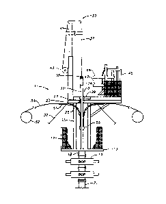
Figure 1 is a partially schematic side elevational view of a unit for running
a string of
tubing and clamping control lines to the tubing.
Figure 2 is a view of the unit of Figure 1, showing an additional joint of
tubing being
secured to the string of tubing.
Figure 3 is a view similar Figure 2, but showing upper slips extended to an
upper
position to engage the string of tubing.
Figure 4 is a view similar to Figure 3, but showing the upper slips and the
string of
tubing being lowered.
-3-
CA 02807146 2013-01-30
WO 2012/018937
PCT/US2011/046460
Detailed Description of the Disclosure:
Referring to Figure 1, unit 11 has a base or rig floor 13. Rig floor 13
supports the
lower ends of a plurality of vertically oriented hydraulic cylinders 15. In
the preferred
embodiment, there are four hydraulic cylinders 15 spaced in a rectangular
array. Rig floor 13
may have a safety fence 17 surrounding it, a portion of which is shown broken
out in the
figures to illustrate hydraulic cylinders 15. Rig floor 13 has an adapter 18
that extends
downward from it to mount unit 11 on a wellhead assembly. In this example,
adapter 18
comprises a tubular member with an external flange on a lower end that bolts
to the upper
end of a blowout preventer assembly (BOP) 19. Adapter 18 secures the unit 11
to the upper
end of BOP 19 and has a passage through it for passing pipes and tools into
the well bore. In
this example, BOP 19 comprises two blowout preventers, one on top the other,
but a single
blowout preventer or more than two would be satisfactory. The lower blowout
preventer of
BOP 19 is connected to the top of a tubing head 21. Tubing head 21 comprises
part of a
wellhead assembly, typically for a land based well.
Unit 11 also has a pipe make-up or support floor 23 positioned above rig floor
13.
Pipe make-up floor 23 is supported on the upper ends of the cylinders of
hydraulic cylinders
15, which serve as legs. Pipe make-up floor 23 has a set of lower slips or a
spider 25 mounted
within it. Lower slips 25 are preferably power actuated and will move between
a pipe
gripping position and a pipe releasing position. Lower slips 25 comprises
segments that slide
downward on conical surfaces of a bowl to engage and are lifted upward
relative to the bowl
by hydraulic cylinders to disengage. In a pipe gripping position, lower slips
25 will support
the weight of a string of pipe. Pipe make-up floor 23 and lower slips 25 are
at a fixed
distance above rig floor 13.
Hydraulic cylinders 15 have pistons 27 that stroke between upper and lower
positions.
In this example, pistons 27 are double acting; that is, they are powered to
extend and retract.
-4-
CA 02807146 2013-01-30
WO 2012/018937
PCT/US2011/046460
A traveling slip base 29 mounts to the upper ends of pistons 27 for movement
therewith.
Traveling slip base 29 is a plate that supports a set of upper slips or a
spider 31. Upper slips
31 may be identical to lower slips 25 except they are moved vertically
relative to lower slips
25 when pistons 27 are stroked between the upper and lower positions. Upper
slips 31 are
also preferably power actuated between a released position and a pipe gripping
position.
Upper slips 31 will also support the weight of a string of pipe. Figure 1
shows upper slips 31
in a lower position, and Figure 3 shows upper slips 31 in an upper position.
In this example,
upper slips 31 only support a downward force due to weight of pipe, and are
not capable of
exerting a downward force on a string of pipe to force pipe into a well under
pressure.
In this embodiment, a string of pipe comprising production tubing 33 is being
lowered
into the well with unit 11. Production tubing 33 comprises sections of pipe,
typically about
30 - 40 feet long, that have external threads at each end. An internally
threaded sleeve or
coupling 34 secures each joint of tubing 33 to another. During running, tubing
string 33
extends through adapter 18, BOP 19, and tubing head 21. After tubing string 33
is completely
installed, BOP 19 is removed and the well is completed. Hydrocarbons being
produced from
the well will flow through tubing string 33 and out flow lines connected to
tubing head 21.
In this embodiment, a lift cap 35 is secured by threads to the coupling 34 on
the
uppermost joint of tubing 33. A lift line 37 extends up over a sheave assembly
39 at the
upper end of a mast 41. Preferably mast 41 is a telescoping type and is
hydraulically actuated
between retracted and extended positions. A winch 43 is mounted to a lower
portion of mast
41, and lift line 37 extends around winch 43. Winch 43 may be actuated to
lower and raise
lift cap 35. Winch 43, lift line 37 and mast 41 have the capability of lifting
a single joint of
tubing string 33, but need not have the capability of supporting an entire
tubing string 33.
A make-up carriage 45 is mounted to pipe make-up floor 23. Make-up carriage 45
moves laterally between an outer storage position inward to an inner
operational position.
-5-
CA 02807146 2013-01-30
WO 2012/018937
PCT/US2011/046460
Figure 1 shows make-up carriage 45 in the storage position and Figure 2 in the
operational
position. Make-up carriage 45 has a drive system (not shown) that will cause
it to move
selectively between the storage and operational positions. Conventional
powered pipe make-
up equipment mounts to make-up carriage 45 for making up couplings 34 of
tubing string 33.
The make-up equipment includes a backup tong 47 and a make-up tong 49 mounted
above
backup tong 47.
A plurality of control lines 51 (two shown) are shown being attached to the
string of
tubing 33 in Figure 1. Control lines 51 may be hydraulic control lines that
supply hydraulic
fluid pressure to various downhole components in the string of tubing 33.
These components
could be valves, sliding sleeves or other devices. The control lines may also
include
electrical lines that supply electrical power and receive signals from sensors
downhole.
Control lines 51 are deployed from spools or reels 52 that would be mounted at
the ground
level. Each control line 51 passes over a guide 53 that bends the control line
in a gradual arc
into vertical alignment alongside tubing string 33. Control lines 51 and
guides 53 are located
below make-up floor 23 and above rig floor 13. Control lines 51 do not pass
through either
of the slips 25, 31; rather they are brought alongside tubing string 33 below
lower slips 25.
Personnel standing on rig floor 13 will connect control lines 51 to tubing
string 33 by using
conventional brackets or clamps 55.
Personnel may also be present on make-up carriage 45 for controlling the make-
up of
tubing string 33 with tongs 47 and 49. Ladders or stairs may be mounted
between rig floor
13 and ground and between make-up floor 23 and ground. A number of guy wires
57 are
preferably connected between make-up floor 23 and ground to provide vertical
stabilization.
In operation, Figure 1 shows tubing string 33 being supported by lower slips
25. The
uppermost joint of tubing string 33 is positioned at a desired elevation above
make-up floor
23 for engagement by backup tongs 47. Pistons 27 are in the fully retracted
position with
-6-
CA 02807146 2013-01-30
WO 2012/018937
PCT/US2011/046460
traveling slip base 29 in it lower position. At that point, the operator will
remove lift cap 35
from tubing string 33 and secure it to a new joint 59 of tubing, also referred
to herein as an
add-on joint. The add-on joint 59, which is shown in Figure 2, will be picked
up from a pipe
rack and lifted so that it is in vertical alignment with tubing string 33 as
shown in Figure 2.
The operator lifts the add-on joint 59 by using winch 43 and lift line 37. The
operator then
moves make-up carriage 45 into the operational position shown in Figure 2.
Backup tong 47
will engage tubing string 33 below coupling 34, and make-up tong 49 will
engage add-on
joint 59, respectively. With make-up tong 49, the operator rotates add-on
joint 59 while
holding tubing string 33 against rotation with backup tong 47. The operator
then disengages
tongs 47, 49 and moves make-up carriage 45 back to the storage position shown
in Figure 3.
While upper slips 31 are in a disengaged position, the operator then will move
traveling slip base 29 to an upper position by causing pistons 27 to move
upward. Once near
the upper position, which is shown in Figure 3, the operator actuates upper
slips 31 to engage
add-on joint 59. The operator then supplies pressure to move pistons 27
farther upward,
causing upper slips 31 to lift the entire tubing string 33, which now includes
add-on joint 59,
a short distance. The operator then will move lower slips 25 to the released
position, with
upper slips 31 supporting the weight of tubing string 33. If the weight of
tubing string 33 is
sufficient, the operator then will allow hydraulic fluid pressure to bleed
from hydraulic
cylinders 15 at a desired rate so as to lower tubing string 33 by gravity
until pistons 27 reach
a fully retracted position. If tubing string 33 comprises only a few joints of
tubing, the
weight may not be sufficient to cause pistons 27 to retract quickly enough. In
that instance,
the operator will apply pressure to pistons 27 to cause them to retract.
Figure 4 shows add-on
joint 59 being lowered from the position in Figure 3. While tubing string 33
descends, the
operator feeds control lines 51 from spools through guides 53 and alongside
tubing string 33.
-7-
CA 02807146 2013-01-30
WO 2012/018937
PCT/US2011/046460
The operator also plays out lift line 37 from winch 43 while tubing string 33
descends so that
no tension will be within lift line 37.
When traveling slip base 29 reaches its lower position, the upper end of add-
on joint
59 will not yet be located in the make-up position above make-up floor 23.
Rather the upper
end of add-on joint 59 will be spaced a greater distance from make-up floor 23
than make-up
tong 49. Depending upon the lengths of pistons 27 and the longer length of add-
on joint 59,
the operator may need to stroke pistons 27 between the extended and retracted
positions a
few times in order to position coupling 34 on add-on joint 59 at a lower
elevation than make-
up tong 49. Consequently, if traveling slip base 29 is still not at the
desired elevation above
make-up floor 23, the operator will repeat the cycle. He will engage lower
slips 25 with
tubing string 33, disengage upper slips 31, and stroke pistons 27 back to near
an uppermost
position to again grip add-on joint 59. Eventually, coupling 34 of add-on
joint 59 will be
located in approximate horizontal alignment with tongs 47, 49, which is
slightly lower than
make-up tong 49. The tubing string 33, now including add-on joint 59, will be
in the position
of Figure 1, ready for receiving an another add-on joint 59 of tubing.
If the operator is securing one clamp 55 for every joint of tubing 33, the
operator will
be in a position to secure a new control line clamp 55 when a new joint 59 of
tubing is to be
added. Personnel located on rig floor 13 will connect clamp 55 around tubing
33, securing
control lines 51.
After running tubing string 33 to the desired depth, a tubing hanger (not
shown) will
be secured to the upper end of tubing string 33 and landed in tubing head 21.
The operator
removes BOP 19 and unit 11 and completes the well for production.
The unit described avoids the need for a workover or drilling rig for running
tubing.
The unit not only runs the tubing, it also facilitates strapping control lines
to the tubing as the
tubing is being lowered into the well.
-8-
CA 02807146 2013-01-30
WO 2012/018937
PCT/US2011/046460
While the disclosure has been shown in only one of its forms, it should be
apparent to
those skilled in the art that it is not so limited but is susceptible to
various changes without
departing from the scope of the disclosure.
-9-