Note: Descriptions are shown in the official language in which they were submitted.
CA 02807200 2013-02-21
253131
AIRFOILS FOR USE IN ROTARY MACHINES
CROSS REFERENCE TO RELATED APPLICATIONS
[0001] This application claims priority to provisional application no.
61/605,041, filed February 29, 2012, the disclosure of which is hereby
incorporated by
reference in its entirety.
BACKGROUND
[0002] The field of the present disclosure relates generally to rotary
machines, and more particularly to airfoils used with rotary machines.
[0003] At least some known rotary machines such as, gas turbine
engines used for aircraft propulsion, include a plurality of rotating blades
that channel air
downstream. Each blade has a cross-sectional shape that defines an airfoil
section.
Conventional single rotation turboprop engines provide high efficiency at low
cruise
speeds (flight Mach number up to about 0.7), although some single rotation
turboprop
engines have been considered for higher cruise speeds. Higher cruise speeds
(Mach 0.7
to 0.9) are typically achieved using a ducted turbofan engine to produce the
relatively
high thrust required.
[0004] Unducted, counter-rotating propeller engines, frequently referred
to as the unducted fan (UDF ), or open-rotor, have been developed to deliver
the high
thrust required for high cruise speeds with higher efficiency than ducted
turbofans.
Counter-rotating propellers for high cruise speed efficiency have strong
acoustic
interactions (i.e., noise generation) at low flight speed, such as takeoff,
typically at flight
Mach number of 0.3 or less. Counter-rotating propellers designed for quiet
operation at
low flight speed tend to be inefficient at high cruise speeds. Thus, a need
exists for both
single rotation and counter-rotating propellers that have both good efficiency
at high
flight speed and low noise at low flight speed.
-1-
CA 02807200 2013-02-21
253131
[0005] To operate at a wide range of operating conditions, propeller
blades are typically attached to rotating hubs such that each blade setting
angle, or pitch,
can be adjusted during flight. Although this adjustment of blade pitch angle
affects
performance, because the blades are essentially rigid, the airfoil sections
that comprise a
blade are shaped in a specific way to improve both efficiency at high speed
flight and
reduce noise at low speed flight. Thus, a need exists for propellers that have
both high
efficiency and low noise at high speed.
BRIEF DESCRIPTION
[0006] In one aspect, an airfoil section of a propeller for a propulsion
device includes a pressure surface and a suction surface, the pressure surface
and suction
surface intersecting at a leading edge and a trailing edge. The airfoil
section has a
meanline defined midway between the pressure surface and the suction surface
and a
meanline angle is defined as an angle between a tangent to the meanline and a
centerline
of the propeller. The blade has a meanline curvature defined as the slope of a
meanline
angle with respect to chord fraction along the meanline, and at least a
portion of the
meanline has meanline curvature that increases from between approximately 0.1
chord
fraction progressing toward the leading edge and at least another portion of
the meanline
has meanline curvature decreases from between approximately 0.1 chord fraction
progressing toward the leading edge.
[0007] In another aspect, an airfoil section for a propeller for a
propulsion device includes a pressure surface and a suction surface, the
pressure surface
and suction surface intersecting at a leading edge and a trailing edge. The
airfoil section
has a meanline defined midway between the pressure surface and the suction
surface and
a meanline angle is defined as an angle between a tangent to the meanline and
a
centerline of the propeller. The airfoil section has a meanline curvature
defined as a slope
of the meanline angle with respect to chord fraction along the meanline, and a
thickness
of the airfoil section is defined as a distance measured normal to the
meanline between
-2-
CA 02807200 2013-02-21
253131
=
the pressure surface and the suction surface, and wherein the airfoil has a
maximum
thickness located between about 0.15 and about 0.25 chord fraction.
[0008] In yet another aspect, an open rotor propulsion device includes a
plurality of propeller blades, each of the propeller blades having at least
one airfoil
section comprising a pressure surface and a suction surface. The pressure
surface and
suction surface intersect at a leading edge and a trailing edge. The at least
one airfoil
section has a meanline defined midway between the pressure surface and the
suction
surface. A meanline angle is defined as an angle between a tangent to the
meanline and a
centerline of the propeller blade, and the meanline has a meanline curvature
defined as
the slope of a meanline angle with respect to chord fraction along the
meanline. The at
least one airfoil section meets at least one of conditions (A) and (B),
wherein: (A) is at
least a portion of the meanline has meanline curvature that increases from
between
approximately 0.1 chord fraction progressing toward the leading edge and at
least another
portion of the meanline has meanline curvature that decreases from between
approximately 0.1 chord fraction progressing toward the leading edge; and (B)
is a
thickness of the airfoil is defined as a distance measured normal to the
meanline between
the pressure surface and the suction surface, and wherein the airfoil has a
maximum
thickness ratio located between about 0.15 to about 0.25 chord fraction, and
the thickness
ratio is 0.8 or greater at approximately 0.1 chord fraction.
BRIEF DESCRIPTION OF THE DRAWINGS
[0009] Fig. 1 is an illustration of an aircraft including an exemplary
propulsion device.
[0010] Fig. 2 is a side view of the exemplary propulsion device shown in
Fig. 1.
[0011] Fig. 3 shows a profile of an exemplary airfoil section of a rotor
blade of the propulsion device shown in Fig. 2.
-3-
CA 02807200 2013-02-21
253131
[0012] Fig. 4 is a plot of meanline angle as a function of a fraction of
chord length of a conventional rotor blade airfoil section and the rotor blade
airfoil
section of Fig. 3.
[0013] Fig. 5 is a plot of a thickness distribution comparison of a
conventional rotor blade compared to the exemplary rotor blade of Fig. 3.
[0014] Fig. 6 is a plot of a meanline curvature comparison for a
conventional rotor blade and the exemplary rotor blade of Fig. 3.
DETAILED DESCRIPTION
[0015] Fig. 1 illustrates an exemplary aircraft 100 including a pair of
wings 102 and 104. Each wing 102 and 104 supports a rotary propulsion device
106 via
a support 108. In other embodiments, one or more rotary propulsion devices 106
may be
mounted to any suitable location on aircraft 100. In another embodiment,
propulsion
device 106 is a counter-rotating propeller engine 110.
[0016] Fig. 2 illustrates a side view of counter-rotating propeller engine
110. Counter-rotating propeller engine 110 has a longitudinal centerline 112.
In the
exemplary embodiment, an engine cowling 114 is disposed co-axially with
centerline
112. Counter-rotating propeller engine 110 includes a core including a
compressor, a
combustor and a turbine, which may be a multi-stage turbine.
[0017] In the exemplary embodiment, counter-rotating propeller engine
110 includes an engine cowling 114 which houses a power generating rotary
machine
(not shown). The rotary machine is coupled to a first set of rotor blades 116
and a second
set of rotor blades 118. In operation, first set of rotor blades 116 and
second set of rotor
blades 118 are in counter-rotation. First set of rotor blades 116 rotates
about hub 120
and second set of rotor blades rotates about a second hub 122, which are
arranged co-
axially with centerline 112. Each of first set of rotor blades 116 and second
set of rotor
blades 118 include a plurality of circumferentially spaced rotor blades 124,
126.
-4-
CA 02807200 2013-02-21
253131
[0018] For a rotating propeller blade, a surface of the blade on an
advancing side thereof, due to rotation, is referred to as the pressure
surface. A surface
on the retreating side of the blade, due to rotation, is called a suction
surface. The leading
edge of a propeller blade is used herein to refer to a three-dimensional curve
at which the
suction surface and pressure surface meet on an upstream edge of the blade,
based on the
flight direction. A trailing edge refers to an intersection of the same
suction surface and
pressure surface on the downstream edge of the blade. The mean surface is used
herein
to refer to the imaginary surface connecting the leading edge to trailing
edge, which lies
midway between the pressure surface and suction surface.
[0019] Fig. 3 shows an airfoil cross section of rotor blade 124 (rotor
blade 126 may be similarly shaped) between a blade attachment point to hub 116
(shown
in Fig. 1) and a tip of rotor blade 124 viewed radially downward toward
centerline 112.
Rotation direction of blade 124 is indicated as a directional arrow in Fig. 3.
In Fig. 3, the
blade surfaces appear as curves and the edges appear as points. In the
exemplary
embodiment, blade 124 includes a pressure surface 134, a suction surface 132,
a leading
edge 131, and a trailing edge 133 (although Fig. 3 is a 2-dimensional
illustration of blade
124, similar conventions are used for the three-dimensional blade). Meanline
130, which
may also be referred to as the camber line, is a two-dimensional view of the
mean surface
of blade 124.
[0020] In the exemplary embodiment, an airfoil section of blade 124 has
a meanline angle 139, which refers to the angle between the tangent to
meanline 130 and
centerline 112. Meanline angle 139 can be measured at any location along
meanline 130,
and is illustrated in Fig. 3 at approximately midway between leading edge 131
and
trailing edge 133. Thickness 136 is a distance measured normal to the meanline
between
the pressure surface 134 and suction surface 132, which can be measured at any
location
along meanline. Thickness 136 is illustrated in Fig. 3 as the distance between
two
opposing arrows at a location approximately midway between leading edge 131
and
trailing edge 133. Chord is defined as a straight line distance between
leading edge 131
and trailing edge 133. A location along meanline 130 of either meanline angle
139 or
-5-
CA 02807200 2013-02-21
253131
thickness 136 may be approximated by a chord fraction. As used herein, chord
fraction
refers to a distance of the location from leading edge 131 to a point of
interest divided by
chord. A maximum thickness 137 of the airfoil section of blade 124 is
represented by
the diameter of an inscribed circle between pressure surface 134 and suction
surface 132.
In one embodiment, maximum thickness location 137 is located at approximately
0.2
chord fraction (i.e., 20 percent of the total distance from leading edge 131
to trailing edge
133.
[0021] As
used herein, camber is defined as a change in meanline angle
139 between any two points along meanline 130. Curvature of meanline 130 is
calculated as the derivative, or slope, of meanline angle 139 with respect to
chord fraction
along meanline 130. Typically, and as used herein, for a propeller airfoil
section in
which the meanline angle generally decreases from leading edge to trailing
edge, camber
is expressed as the meanline angle change from one specified point along the
meanline to
another specified point closer to the leading edge (i.e., positive camber is
where the
meanline angle increases progressing toward the leading edge). Similarly,
curvature is
considered positive for an increasing meanline angle in a direction toward the
leading
edge, although the slope of the meanline angle distribution is mathematically
negative for
positive curvature.
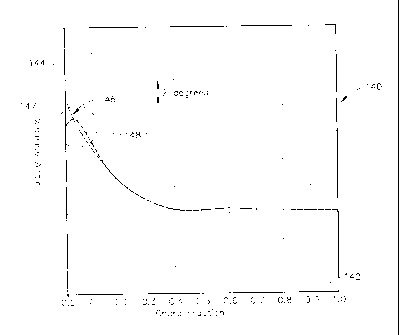
[0022] Fig. 4 is a graph 140 illustrating meanline angle of two airfoil
sections across their respective chord fractions. Graph 140 includes a
horizontal axis 142
graduated in units of chord fraction and a vertical axis 144 graduated in
degrees. A trace
of meanline angle distribution for a conventional low noise airfoil section is
indicated as
line 146, and a trace of meanline angle distribution for a low noise and high
speed
efficiency airfoil section (e.g., such as within blade 124 or 126) is
indicated as line 148.
The conventional low noise airfoil section's meanline angle distribution 146
has an angle
increase (i.e. camber) from 0.5 chord fraction to the leading edge that is
several degrees
more than for a conventional design for high speed efficiency (not shown). The
higher
camber of conventional low noise airfoil 146, relative to a conventional
design for high
speed efficiency, tailors the suction surface of the airfoil to reduce flow
separation near
-6-
CA 02807200 2013-02-21
253131
the leading edge, which would otherwise produce acoustic interactions (i.e.,
noise
generation) with downstream counter-rotating blades or other structures. As
shown in
Fig. 4, the conventional low noise airfoil's meanline angle distribution 146
is substantially
smooth and monotonically increases from about 0.1 chord fraction progressing
toward
the leading edge. It is noted that the leading edge is represented as 0.0
chord fraction. At
high flight speed, conventional low noise airfoil's meanline angle
distribution 146 results
in flow losses (i.e., an efficiency penalty) near the leading edge thereof due
to separated
airflow on the pressure surface thereof In the exemplary embodiment, in region
147
progressing from approximately 0.1 chord fraction toward the leading edge
(i.e., chord
fraction 0.0), the meanline angle of the low noise and high speed efficiency
airfoil 148
initially increases compared to the conventional low noise airfoil's meanline
angle
distribution 146. However, continuing toward leading edge and over a short
distance of
approximately 0.05 chord fraction, the increase in meanline angle 148 is less
than the
increase in meanline angle 146.
[0023] In one embodiment, the above described region 147, having an
increase followed by a decrease in slope of meanline angle distribution 148 as
compared
to meanline angle distribution 146, is accompanied by a modification to the
thickness
distribution along meanline 130 of an airfoil section within blade 124 that
shifts
maximum thickness location 137 forward (toward leading edge 131) from
approximately
0.4 chord fraction to approximately 0.2 chord fraction. In the exemplary
embodiment,
additional thickness is also added to an airfoil section within blade 124 from
approximately 0.0 to approximately 0.15 chord fraction, so that suction
surface 132
coincides closely to a suction surface of a conventional low noise airfoil
section and the
thickness ratio greater than 0.8 at 0.1 chord fraction. The resulting pressure
surface 134 is
thus farther from suction surface 132 than for a conventional low noise
airfoil section,
thereby increasing a radius of curvature for the airflow around pressure
surface 134 near
leading edge 131, as compared to a conventional airfoil section, to reduce
airflow
separation and loss of efficiency in high speed flight.
-7-
CA 02807200 2013-02-21
253131
[0024] Fig. 5 is a graph 150 illustrating thickness ratios of two airfoil
sections across their respective chord fractions. Graph 150 includes a
horizontal axis 152
graduated in units of chord fraction and a vertical axis 154 expressed as
thickness ratio
(i.e., airfoil section thickness at a point of interest divided by its maximum
thickness).
The conventional low noise airfoil section thickness ratio 156 (as well as for
an airfoil
section designed solely for high speed efficiency) peaks (i.e., is maximum) at
approximately 0.4 chord fraction. In contrast, for the airfoil section of the
exemplary
embodiment designed for low noise and high efficiency (i.e., within blade 124
or blade
126) thickness ratio 158 is substantially increased in between the 0.0 to 0.20
chord
fraction range, as compared to the conventional airfoil section. In one
embodiment, a
peak thickness 159 of the airfoil section of blade 124 is at approximately
0.20 chord
fraction.
[0025] Fig. 6 is a graph illustrating meanline curvature of two airfoil
sections across their respective chord fractions. Graph 160 includes a
horizontal axis 162
graduated in units of chord fraction and a vertical axis 164 expressed as
camber per unit
chord. A trace of curvature distribution 166 for a conventional low noise
airfoil section is
plotted alongside a trace of curvature distribution 168 of an exemplary low
noise and
high speed efficiency airfoil section (i.e., within blade 124 or blade 126) on
graph 160.
For conventional low noise curvature distribution 166, the curvature increases
or remains
substantially constant from about 0.1 chord fraction to the leading edge. For
the
exemplary low noise and high speed efficiency airfoil section, the curvature
distribution
168 increases then sharply decreases from about 0.1 chord fraction to the
leading edge.
[0026] In one embodiment, the oscillation in curvature (i.e., the
curvature distribution 168 increases then sharply decreases from about 0.1
chord fraction
to the leading edge) occurs at least once between 0.1 and about 0.0 chord
fraction of
blade 124 and is accompanied by thickness distribution that maintains suction
surface
132 to be suitable for a low noise airfoil. In one embodiment, the curvature
increase and
decrease are each about 10 degrees per unit chord in magnitude or greater, and
each
occurs over less than approximately 0.05 chord fraction. However, other
curvature and
-8-
CA 02807200 2013-02-21
253131
thickness distributions along the meanline may be used within the scope of the
present
disclosure.
[0027] This written description uses examples to disclose the invention,
including the best mode, and also to enable any person skilled in the art to
practice the
invention, including making and using any devices or systems and performing
any
incorporated methods. The patentable scope of the invention is defined by the
claims,
and may include other examples that occur to those skilled in the art. Such
other
examples are intended to be within the scope of the claims if they have
structural
elements that do not differ from the literal language of the claims, or if
they include
equivalent structural elements with insubstantial differences from the literal
languages of
the claims.
-9-