Note: Descriptions are shown in the official language in which they were submitted.
CA 02807204 2013-02-25
1
Device for error correction for CNC machines
The present invention relates to a method and a device for determining a
positioning error
of a computerized numerical control (CNC) machine, in particular, to a method
and a
device for determining a positioning error of a CNC machine tool head and/or
CNC
machine table.
EP 1 549 459 teaches a method and device for determining a positioning error
of a CNC
machine tool head or machine table, wherein a support base is equipped with a
plurality of
distance sensors to determine the Cartesian coordinates of a gauge tool
equipped with a
ball. In order to determine the positioning error of the tool head, the
plurality of distance
sensors measure the respective distances to the ball. Then the tool head or
table
performs an angular motion whereas at the same time the machine performs a
circular or
helical counter motion such that the ball of the gauge tool remains in its
position. Then the
plurality of distance sensors measure the respective distances to the ball
again. Due to a
positioning error of the tool head these distances may differ. Then the
machine is caused
to perform a linear motion with respect to the Cartesian coordinate axes so
that the
plurality of distance sensors measure the original distances again, whereas at
the same
time the angular position of the head or table remains fixed. From this
compensation
movement, the positioning error of the head or table can be determined as the
linear
motions which were necessary to compensate the positioning error of the head
or table.
The device of EP 1 549 459 has the disadvantage that the control of the CNC
machine
has to be able to read and process the data from the plurality of sensors.
This may be
disadvantageous when there is no common interface between the plurality of
sensors and
the CNC machine available, e.g. because both devices were fabricated by
different
manufacturers.
In view of the prior art, there is a need for a method and device for
determining a
positioning error of a CNC machine, in particular, of a CNC machine tool head
and/or a
CNC machine table, which works independently of the control of the CNC machine
and, in
particular, requires no common interface with the control of the CNC machine.
It is, therefore, and object of the present invention to overcome the
aforementioned
shortcomings of the prior art.
CA 02807204 2013-02-25
2
The present invention provides a method for determining a positioning error of
a a CNC
machine, wherein the CNC machine is equipped with a calibration element, the
calibration
element being in a first position, the method comprising the steps of
reading first sensor data from at least one sensor while the calibration
element is at the
first position,
wherein the sensor data correspond to a distance between a point on the
surface of the
calibration element and the at least one sensor, or
wherein a contact element of the at least one sensor is deflected by the
calibration
element and the sensor data correspond to a distance by which the contact
element is
deflected,
operating the CNC machine to perform a calibration movement that ideally
leaves the
calibration element at the first position,
reading second sensor data from the at least one sensor the calibration
element is at a
second position, wherein the second position denotes the actual position of
the calibration
element after the calibration movement has been performed,
causing the at least one sensor to move so that the difference between the
first and
second sensor data decreases until the difference becomes less or equal to a
pre-
determined threshold value, and
determining a positioning error of the CNC machine based on the movement of
the at
least one sensor.
The computerized numerical control (CNC) machine can be any CNC machine known
in
the art, in particular, a machine tool and/or a robot. The CNC machine may be
operated in
the Rotations along Tool Center Point (RTCP) mode. The CNC machine may
comprise a
tool head, in particular, a rotary head, like a bi-rotary milling head. The
CNC machine may
comprise a machine table, in particular, a movable machine table, like a
rotary table
and/or a rotary tilting table. A tool head and/or a machine table may be
equipped with the
calibration element.
CA 02807204 2013-02-25
3
A tool head may denote an interface between the CNC machine and a tool, in
particular, a
tool for shaping, such like milling, drilling, or cutting. Other tools, like
measuring or testing
tools, are also possible. For performing above-described method, it is
preferable to
replace a removable tool with the calibration element. However, it is also
possible to use
the tool itself as the calibration element, which is advantageous if the tool
is not removable
or difficult to remove.
A machine table may hold and/or move, in particular, rotate, a work piece. For
performing
above-described method, it is preferable to replace the work piece with the
calibration
element. The calibration element may be placed on and/or fixed to the machine
table.
The calibration element may comprise a solid or hollow ball, in particular, a
ball made from
a hard material like metal. The ball may have the shape of a sphere, wherein
the shape
may be of a high geometrical accuracy but need not be geometrically perfect.
The ball
may be connected to the tool head by a cylinder. Other shapes of the
calibration element
are possible. In particular, the calibration element may comprise an ellipsoid
and/or a
cylinder.
The at least one sensor can be one sensor, two sensors, three sensors, or more
than
three sensors, which can be mounted on a common support base.
One or more of the sensors can be a distance sensor which outputs sensor data
corresponding to the distance between a point on the surface of the
calibration element
and the sensor. The distance sensor may, in particular, be a sensor that is
not in physical
contact with the calibration element. For example, one or more of the sensors
can be an
optical sensor, in particular, a laser sensor, an acoustic sensor, in
particular, an ultrasonic
sensor, a capacitive sensor, and/or an inductive sensor.
One or more of the sensors can be a contact point sensor and/or a dial
indicator which
comprises a deflectable portion and a non-deflectable portion. The deflectable
portion
may comprise a contact element which is in contact with the calibration
element, more
specifically, with a point on the surface thereof. The one or more contact
point sensors
output sensor data which corresponds to a distance by which the deflectable
portion, in
particular, the contact element thereof, is deflected by the calibration
element, in
particular, by a point on the surface thereof. A contact point sensor may, in
particular,
comprise a geometrical sensor axis along which the contact element may be
deflected.
CA 02807204 2013-02-25
4
Then the contact element is deflected by the point on the surface of the
calibration
element which is on the geometrical sensor axis.
In one step of the method the at least one sensor outputs first sensor data
while the
calibration element is at the first position. That is, the first sensor data
represents the first
position of the calibration element, in particular, the center of a ball
thereof. This first
position may be known to the CNC control, but unknown to the at least one
sensor. It is
however not necessary to compute the first position of the calibration element
from the
first sensor data. In particular, it is not important which point on the
surface of the
calibration element is taken to represent the first position. This has the
advantage of a
greater freedom in positioning of the at least one sensor. In particular, the
sensors need
not be orthogonally positioned. In fact, they need not be positioned very
precisely.
In another step of the method the CNC machine is operated to perform a single
movement or a sequence of movements which, according to the CNC control, would
not
move the calibration element, in particular, the center of a ball thereof,
from its first
position. The CNC machine may be operated to cause a tool head and/or a
machine table
thereof to perform a single movement or a sequence of movements which,
according to
the CNC control, would not move the calibration element, in particular, the
center of a ball
thereof, from its first position. The CNC machine may be operated in the RTCP
mode
while performing said movement or sequence of movements. Such movements may
comprise rotations about various axes. In particular, when the calibration
element
comprises a ball, the first position may be represented by the center of the
ball by the
CNC control. Then, a movement that does not move the calibration element from
its first
position means that the center of the ball does not move. The ball may,
however, be
rotated about any axis through its center. If the ball is connected to the CNC
machine, in
particular to a tool head or a machine table thereof, by an element, like a
cylinder, said
element itself may be moved during the movement.
Although ideally, that is, according to the CNC control, the calibration
element, in
particular, the center of a ball thereof, has not moved during the movement,
in reality it
can have moved due to a positioning error caused by a geometrical mechanical
error of
the CNC machine, in particular, of a tool head or machine table thereof. That
is, the actual
position of the calibration element, in particular, the center of a ball
thereof, at this point is
CA 02807204 2013-02-25
known neither to the CNC control, nor to the at least one sensor. In fact, the
CNC control
assumes that the first and second positions of the calibration element are the
same.
In another step of the method the at least one sensor outputs second sensor
data while
the calibration element, in particular, the center of a ball thereof, is at a
position after the
5 movement. The point on the surface of the calibration element may be a
different point or
the same point as the point corresponding to the first sensor data. The second
sensor
data represents the second position of the calibration element, in particular,
the center of
a ball thereof.
In another step of the method the at least one sensor is caused to move so
that the
difference, in particular, the absolute difference, between the first and
second sensor data
decreases, thereby partially or fully compensating the positioning error by
sensor
movement. This movement may be monitored in a takt time or in real time, and
adjusted
upon feedback. Alternatively, this movement may be partially or completely
calculated in
advance from the first and second sensor data data indicating the sensor
movement may
be stored for further processing.
The at least one sensor may comprise a movement element for moving the at
least one
sensor, or be mounted to the movement element. The at least one sensor may
also be
mounted to a support base which comprises a movement element for moving the
support
base, or be mounted to the movement element. In particular, at least two
sensors,
preferably at least three sensors, may be mounted to a common support base
which is
equipped with a movement element for moving the support base and, therefore,
moving
the sensors concurrently.
When the difference, in particular, the absolute difference, between the first
and second
sensor data becomes less or equal to a threshold value, the current sensor
data equals
the first sensor data within an acceptable range. The threshold value may be
the
graduation and/or accuracy of the at least one sensor and/or the CNC machine
control.
The threshold value may be a percentage of the first sensor data, in
particular 1% or 0.1%
thereof, or correspond a fixed value, in particular, 10 pm, preferably 5 pm,
or more
preferably 3 pm. The smaller the value, the more precise is the result.
In another step of the method, the positioning error of the tool head, in
particular, the
center of a ball thereof, with respect to the movement of the tool head, in
particular, the
CA 02807204 2013-02-25
6
center of a ball thereof, is determined based on the movement of the at least
one sensor.
The movement of the at least one sensor may be a superposition of all
movements which
were performed so that the current sensor data equals the first sensor data
within the
above-described range. More specifically, the error may be determined from
data
indicating the movement of the at least one sensor. This has the advantage
that no
common interface between the at least one sensor and the control of the CNC
machine is
necessary for determining the position error.
The method may further comprise the steps of determining, from the first and
second
sensor data, in particular, from the difference thereof, a first compensation
direction, in
such a way that a movement of the at least one sensor in the first
compensation direction
will decrease the difference between the first and second sensor values, and
causing the
at least one sensor to move in the first compensation direction.
By comparing the first and second sensor data, in particular from the
difference of the first
and second sensor data, a direction in which the first and second positions of
the
calibration element differ can be determined. In other words, from the
difference of the first
and second sensor data, a direction in which the calibration element has moved
during
the movement can be determined. This direction need not be the exact direction
of the
actual displacement vector of the calibration element with respect to the
movement. This
has the advantage that the measurement does not have to be precise. The first
compensation direction may then be the direction opposite to said direction,
so that a
movement of the at least one sensor in the first compensation direction will
fully or
partially compensate the displacement vector and, therefore, decrease the
difference, in
particular, the absolute difference, between the first and second sensor data.
The step of determining a first compensation direction may comprise
determining a
velocity vector so that a corresponding movement will move the at least one
sensor in the
first compensation direction.
The step of determining a first compensation direction may further comprise
determining a
first compensation value which may indicate a distance in the first
compensation direction,
wherein the distance may correspond to a necessary distance to fully or
partially
compensate the displacement vector by moving the at least one sensor in the
first
compensation direction.
CA 02807204 2013-02-25
7
The at least one sensor may be caused to move in the first compensation
direction to fully
or partially compensate the difference between the first and second sensor
data, wherein
the at least one sensor may be caused to move into said direction for a pre-
set time. This
pre-set time may be a takt time. That is, the movement in the first
compensation direction
will be initiated and maintained until a different compensation direction is
determined
based on subsequently read sensor data.
Alternatively, the at least one sensor may be caused to move into said
direction for a pre-
set or calculated distance. A pre-set distance may be a constant increment
which may be
the same for all sensor movements and, in particular, may be independent from
the first
compensation direction. A calculated distance may be the first compensation
value or be
calculated based on the first compensation value.
The method, in particular, the causing step, may further comprise performing a
closed-
loop comprising the steps of reading the current sensor data from at least one
sensor,
determining, from the first and current sensor data, in particular, from a
difference thereof,
a current compensation direction, in such a way that a movement of the at
least one
sensor in the current compensation direction will decrease the difference,
between the
first and current sensor data, and causing the at least one sensor to move in
the current
compensation direction.
The step of reading current sensor data may be implemented as a first step in
the loop, or
as a later step in the loop. In particular, in a first execution of the loop,
the current sensor
data may be the second sensor data.
The sensor data of the at least one sensor may be continuously monitored so
that current
sensor data is continuously read. Current sensor data may also be read in
certain time
intervals. This time interval may a takt time, or a fraction thereof, or a
multiple thereof.
From the difference between the first and current sensor data a current
compensation
direction may be determined. The current compensation direction can be an
opposite
direction of a direction defined by the difference between the first and
current sensor data.
That is, the current compensation direction is a direction that, when moving
the at least
one sensor in said direction, will result in a decrease in the difference, in
particular, the
absolute difference, between the current and first sensor data.
CA 02807204 2013-02-25
8
The step of determining a current compensation direction may further comprise
determining a current compensation value which may indicate a distance
necessary to
fully or partially compensate the displacement vector by moving the at least
one sensor in
the current compensation direction.
The at least one sensor may be caused to move into the current compensation
direction
for a pre-set time. This pre-set time may be a takt time. That is, the
movement in the
current compensation direction will be initiated and maintained until a
different
compensation direction is determined in a subsequent loop.
Alternatively, the at least one sensor may be moved by a pre-set or calculated
distance. A
pre-set distance may be a constant increment which may be the same for all
sensor
movements and, in particular, may be independent from the current compensation
direction. A calculated distance may be the current compensation value or be
calculated
based on the current compensation value.
During and/or after the movement the current sensor data may be read again,
and the
loop may restart with the new current sensor data. At the end of the loop, it
may be
determined if the difference, in particular, the absolute difference, between
the current and
first sensor data falls below a threshold value. If so, the loop may end.
The method, in particular, the step of determining the first and/or current
compensation
direction may comprise transforming the sensor data into components with
respect to a
pre-determined coordinate system, in particular, an orthogonal coordinate
system.
The at least one sensor may comprise a geometrical sensor axis and the sensor
data may
correspond to a distance on the geometrical sensor axis. In particular, the
sensor axis
may be fixed. A displacement vector corresponding to the distance on the
geometrical
sensor axis can then be expressed in terms of a pre-determined coordinate
system. This
coordinate system may be an orthogonal, preferably an orthonormal coordinate
system,
such as a Cartesian coordinate system. The displacement vector can further be
decomposed into components with respect to the coordinate system.
In particular, when using a Cartesian coordinate system with coordinates x, y
and z, the
sensor data can be expressed by three components Sx, Sy, Sz, so that the
distance S on
the geometrical sensor axis satisfies S2 = sx2 + sy2 + ,-,z2.
Analogously, when at least two
CA 02807204 2013-02-25
9
sensors are used, the respective distances Si, S2, etc. on the respective
geometrical
sensor axes may be expressed in respective coordinates S1, Sty, S1,, S2,x,
S2,y, S2,z, etc.
Reading the first, second and/or current sensor data may comprise reading the
first,
second and/or current sensor data from at least two sensors and wherein
determining the
first and/or current compensation direction may comprise determining
components of a
velocity vector with respect to the pre-determined coordinate system, in
particular, an
orthogonal coordinate system, so that a corresponding movement of the at least
one
sensor will decrease the absolute difference between the first and current
sensor data.
In particular, determining the velocity vector may comprise weighting the
components of
the velocity vector over the relative difference between the components of the
first and
current sensor data.
Alternatively, determining the first and/or current compensation direction may
comprise
averaging the respective components of the at least two sensors, or adopting
the
respective component having the greatest absolute value, or adopting the
respective
component having the lowest absolute value.
In particular, reading the first, second and/or current sensor data may
comprise reading
the first, second and/or current sensor data from at least three sensors, and
wherein
determining the first and/or current compensation direction may comprise
determining
components of a velocity vector with respect to the pre-determined coordinate
system, in
particular, an orthogonal coordinate system, so that a corresponding movement
of the at
least one sensor will decrease the absolute difference between the first and
current
sensor data, wherein determining the velocity vector may comprise weighting
the
components of the velocity vector over the relative difference between the
components of
the first and current sensor data of the sensors.
The threshold value may be expressed in terms of the coordinate system, in
particular, the
threshold value may be expressed in terms of components with respect to the
coordinate
system, or be expressed in terms of the sensor data. In other words, the
threshold value
may be expressed directly in terms of the sensor data, or in terms of the pre-
determined
coordinate system.
CA 02807204 2013-02-25
In particular, when using a Cartesian coordinate system, the threshold value T
may be
expressed in components Tx, Ty, T, with respect to the Cartesian coordinates
x, y and z.
Then the threshold condition may be expressed as Sy Ty
and Sz T. The
threshold value T may be the same or different for each sensor. That is, for
example for
5 two sensors, we can have the conditions
S1 and S2 wherein T1 and T2 may be
the same or different.
The at least one sensor may be caused to move by translation along at least
one
coordinate axis of the coordinate system. In particular, when using a
Cartesian coordinate
system, the at least one sensor may be caused to translate along the x, y and
z-axis. The
10 at least one senor may comprise a movement element, or be fixed to a
movement
element, wherein the movement element comprises at least one motors, e.g. an
electro-
motor, wherein the at least one motor is configured to translate the at least
one sensor
along the x-axis, y-axis or z-axis. The movement element may comprise at least
three
motors, e.g. electro-motors, wherein at least one of the at least three motors
is configured
to translate the at least one sensor along the x-axis, y-axis and z-axis,
respectively.
The at least one sensor may be caused to move along each of the coordinate
axes of the
coordinate system separately. In other words, the at least three motors can be
controlled
separately.
At least two sensors may be caused to move together, in particular, wherein
the at least
two sensors may be fixed to a common support base. The at least two sensors
may be
mounted on the support base, wherein the at least two sensors can be fixed to
the support
base directly or via one or more elements, e.g. pedestals or sockets. The
pedestals and/or
sockets may comprise one or more cylinders. The support base may comprise a
movement element for moving the support base and thereby also the at least two
sensors.
The at least two sensors may be arranged so that some sensor axes are non-
parallel. In
particular, the at least two sensors, in particular, at least three sensors,
may be arranged
so that at least two sensors thereof, in particular, at least three sensors,
have mutually
non-parallel sensor axes. The at least two sensors may further be arranged so
that all
sensor axes are mutually non-parallel.
Three sensors may be fixed at the edges of an imaginary triangle formed
parallel to a
surface of the support base, wherein each of the sensors is directed to the
center of the
CA 02807204 2013-02-25
11
triangle and inclined against the surface of the support base. Here imaginary
means that
there need not be an actual triangle indicated on or over the surface. In
particular, the
three sensors may be fixed at the edges of an imaginary equilateral triangle,
wherein the
calibration element in its first position may be located over the center of
the triangle. The
three sensors may be inclined against the surface by an inclination angle,
wherein the
angle may be in a range of 40 to 80 , preferably 50 to 70 or 55 to 65 , or
essentially
600, where essentially means that the inclination angle may differ from 60 by
a value
acceptable in the field. The inclination angles of the three sensors can be
the same or
different. In particular, at least one of the three sensors, preferably at
least two of the three
sensors or all three sensors, may point at the center of a ball of the
calibration element.
The three sensors may be pointed so that at least two of the three sensor axes
form an
angle of at least 90 . The three sensors may be pointed so that the sensor
axes of the
three sensor axes form a mutual angle of at least 90 . When a Cartesian
coordinate
system is used, two coordinate axes may be parallel to the surface of the
support base
and one coordinate axis may be perpendicular to the surface of the support
base. In
particular, the coordinate axis perpendicular to the surface, e.g. the z-axis,
may represent
a height, whereas the coordinate axes parallel to the surface, e.g. x-axis and
y-axis, may
represent lateral dimensions.
The method may further comprise outputting data indicating the positioning
error of the
tool head, in particular, wherein outputting comprises any one of displaying,
printing,
transmitting, and/or saving the data. In particular, the determined
positioning error may be
transformed into data readable by a computer system, in particular, the
operation system
of the CNC control.
The invention further provides a method for improving the accuracy of a CNC
machine,
the method comprising determining a positioning error of the CNC machine, in
particular
of a tool head and/or a machine table thereof, by performing any one of the
methods as
described hereinbefore, and compensating the positioning error of the CNC
machine, in
particular of a tool head and/or machine table thereof. Compensating the
positioning error
of the CNC machine, in particular of a tool head and/or machine table thereof,
may
comprise adjusting the programming of the CNC machine based on the positioning
error,
and/or may further comprise inputting data indicating the positioning error of
the tool head
into the CNC machine control.
CA 02807204 2013-02-25
12
The invention further provides a device for determining a positioning error of
a CNC
machine, wherein the CNC machine is equipped with a calibration element, the
device
comprising
at least one sensor, wherein at least one sensor is configured to output
sensor data,
wherein the sensor data corresponds to a distance between a point on the
surface of the
calibration element and the at least one sensor, or wherein a contact element
of the at
least one sensor is deflected by the calibration element and the sensor data
corresponds
to a distance by which the contact element is deflected,
a movement element for moving the at least one sensor, and
a control unit for processing the sensor data received from the at least one
sensor, and for
controlling the movement element, wherein the control unit is configured to
receive first
and second sensor data, output drive data to the movement element which causes
the
movement element to move the at least one sensor so that the difference
between the
first and second sensor data decreases until the difference becomes less or
equal than a
threshold value, and determine a positioning error of the tool head based on
the
movement of the at least one sensor.
The CNC machine can be any CNC machine as known and used in the field, in
particular,
a machine tool and/or a robot. The CNC machine may be operated in the
Rotations along
Tool Center Point (RTCP) mode. The CNC machine may comprise a tool head, in
particular, a rotary head like a bi-rotary milling head. The CNC machine may
comprise a
machine table, in particular, a movable machine table, like a rotary table
and/or a rotary
tilting table. A tool head and/or a machine table may be equipped with a
calibration
element.
A tool head may denote an interface between the CNC machine and a tool, in
particular, a
tool for shaping, such like milling, drilling, or cutting. Other tools, like
measuring and/or
testing tools, are also possible. A machine table may hold and/or translate
and/or rotate a
work piece.
The CNC machine, in particular, a tool head and/or machine table thereof, is
equipped
with a calibration element, wherein the calibration element can be an element
used only
for the purpose of calibrating the CNC machine and/or determining a
positioning error of
CA 02807204 2013-02-25
13
the CNC machine, in particular, of a tool head and/or a machine table thereof.
The
calibration element can also be a tool itself.
The at least one sensor can be one sensor, two sensors, three sensors, or more
than
three sensors, which can be mounted on a common support base.
One or more of the sensors can be a distance sensor which outputs sensor data
corresponding to the distance between a point on the surface of the
calibration element
and the sensor, wherein the distance sensor may, in particular, be a sensor
that is not in
physical contact with the calibration element. For example, one or more of the
sensors
can be an optical sensor, an acoustic sensor, a capacitive sensor, and/or an
inductive
sensor.
One or more of the sensors can be a contact point sensor and/or a dial
indicator which
comprises a deflectable portion and a non-deflectable portion. The deflectable
portion
may comprise a contact element which is in contact with the calibration
element, more
specifically a point on the surface thereof. The one or more contact point
sensors output
sensor data which corresponds to a distance by which the deflectable portion,
in
particular, the contact element thereof, is deflected by the calibration
element, in
particular, by a point on the surface thereof. A contact point sensor may, in
particular,
comprise a geometrical sensor axis along which the contact element may be
deflected.
Then the contact element is deflected by the point on the surface of the
calibration
element which is on the geometrical sensor axis.
The movement element may be fixed to the at least one sensor, or fixed to a
support
base, wherein the at least one sensor can be mounted on said support base.
The control unit may comprise processing means for processing the sensor data
and/or
other data. The control unit may further comprise storage means for caching
data and/or
storing data permanently. The control unit may further comprise an input
interface for
receiving sensor data from the at least one sensor, wherein the at least one
sensor may
communicate with the control unit via a wired connection and/or a wireless
connection,
and/or receiving other data and/or instructions. The control unit may further
comprise an
output interface for outputting data to the movement element, wherein the
movement
element may communicate with the control unit via wired connection and/or
wireless
connection, and/or the output unit and/or other units.
CA 02807204 2013-02-25
14
The control unit may receive first and second sensor data while the
calibration element is
in a first and second position of the calibration element, respectively,
wherein the first
position may refer to an initial position, that is, a position before a
movement of the
calibration element. The second position of the calibration element may refer
to a
subsequent position after a movement of the calibration element, in
particular, a
movement which ideally, that is according to the CNC control, leaves the
calibration
element in a fixed position. The first and second sensor data may be received
via the
input interface.
The control unit may compute, from the first and second sensor data, in
particular, from a
difference thereof, a direction in which the at least one sensor may be moved
so that the
difference, in particular, the absolute difference, between the first and
second sensor data
decreases, and output according movement data to the movement element. This
outputting of movement data may be performed via the output interface.
The control unit may be configured to perform any one of the methods as
described
hereinbefore.
In particular, the control unit may be configured to perform a step of
determining, from the
first and second sensor data, in particular, from the difference thereof, a
first
compensation direction, wherein movement of the at least one sensor in the
first
compensation direction will decrease the difference, in particular, the
absolute difference,
between the first and second sensor values, and causing the at least one
sensor to move
in the first compensation direction.
The control unit may further be configured to perform a closed-loop comprising
the steps
of determining, from the first and current sensor data, in particular, from
the difference
thereof, a current compensation direction, wherein movement of the at least
one sensor in
the current compensation direction will decrease the difference, in
particular, the absolute
difference, between the first and current sensor values, causing the at least
one sensor to
move in the current compensation direction, and reading the current sensor
data from at
least one sensor.
The control unit may be configured to transform the sensor data into
components with
respect to a pre-determined coordinate system, in particular, an orthogonal
coordinate
system.
CA 02807204 2013-02-25
The control unit may be configured to read the first, second and/or current
sensor data
from at least two sensors, in particular, from at least three sensors, and
wherein
determining the first and/or current compensation direction may comprise
determining
components of a velocity vector with respect to the pre-determined coordinate
system, in
5 particular, an orthogonal coordinate system, so that a corresponding
movement of the at
least one sensor will decrease the absolute difference between the first and
current
sensor data.
The control unit may be further configured to express the threshold value in
terms of the
coordinate system, in particular, the threshold value may be expressed in
terms of
10 components with respect to the coordinate system, or to express the
threshold value in
terms of the sensor data.
Moreover, the control unit may be configured to output movement data causing
the
movement element to move the at least one sensor by translation along at least
one
coordinate axis of the coordinate system.
15 The device may further comprise an output unit configured to output
error data
corresponding to the positioning error of the tool head, wherein outputting
comprises any
one of displaying, printing, transmitting and/or saving the error data.
The output unit may be a display device, a printing device, a transmission
device and/or a
storage device, and/or may be connected to a display device, a printing
device, a
transmission device and/or a storage device. The output device may also be
connected to
the CNC machine.
At least one sensor may be a contact point sensor, a dial indicator, a light
sensor, a laser
sensor, an ultrasonic sensor, a capacitive sensor, and/or an inductive sensor.
The movement element may comprise at least one motor, in particular, at least
one
electro-motor. The movement element, in particular, a motor of the movement
element,
may move the at least one sensor by translation along at least one coordinate
axis of a
coordinate system, in particular, an orthogonal coordinate system. In
particular, the at
least one sensor may be mounted to a support base and the at least one motor
may move
the support base and thereby the at least one sensor by translation along at
least one
coordinate axis of a coordinate system, in particular, an orthogonal
coordinate system.
CA 02807204 2013-02-25
16
The movement element may comprises at least two motors, wherein the at least
two
motors can be controlled separately, in particular, wherein the movement
element may
move the at least one sensor and/or the support base by translation along at
least two
coordinate axes separately. The motors may be configured to move the at least
one
sensor and/or the support base directly or via gears. The motors may be
located in a
distance to the at least one sensor and/or support base and comprise gear
shafts that are
connected to the at least one sensor and/or support base.
The movement element may be configured to move at least two sensors together,
in
particular, wherein the at least two sensors are fixed to a common support
base. The
movement element may also be configured to move the support base and thereby
the at
least two sensors.
The at least two sensors may be arranged so that some sensor axes are non-
parallel. In
particular, the least two sensors, in particular, at least three sensors, may
be arranged so
that at least two sensors thereof, in particular, at least three sensors, have
mutually non-
parallel sensor axes. The at least two sensors may further be arranged so that
all sensor
axes are mutually non-parallel.
Three sensors may be fixed at the edges of an imaginary triangle formed
parallel to a
surface of the support base, wherein each of the sensors is directed to the
center of the
triangle and inclined against the surface of the support base. Here imaginary
means that
there need not be an actual triangle indicated on or over the surface. In
particular, the
three sensors may be fixed at the edges of an imaginary equilateral triangle,
wherein the
calibration element in its first position may be located over the center of
the triangle. The
three sensors may be inclined against the surface by an inclination angle,
wherein the
angle may be in a range of 40 to 80 , preferably 50 to 70 or 55 to 65 , or
essentially
60 , where essentially means that the inclination angle may differ from 600 by
a value
acceptable in the field. The inclination angles of the three sensors can be
the same or
different. In particular, at least one of the three sensors, preferably at
least two of the three
sensors or all three sensors, may point at the center of a ball of the
calibration element.
The three sensors may be pointed so that at least two of the three sensor axes
form an
angle of at least 90 . The three sensors may be pointed so that the sensor
axes of the
three sensor axes form a mutual angle of at least 90 . When a Cartesian
coordinate
system is used, two coordinate axes may be parallel to the surface of the
support base
CA 02807204 2015-02-19
17
and one coordinate axis may be perpendicular to the surface of the support
base. In
particular, the coordinate axis perpendicular to the surface, e.g. the z-axis,
may represent a
height, whereas the coordinate axes parallel to the surface, e.g. x-axis and y-
axis, may
represent lateral dimensions.
The calibration element may comprise a ball. The ball may be connected to the
tool head
via an element, in particular, a cylinder. The ball may be formed of a hard
material, e.g. a
metal.
Accordingly, in one aspect the present invention resides in a method for
determining a
positioning error of a CNC machine, wherein the CNC machine is equipped with a
calibration element, the calibration element being in a first position, the
method comprising
the steps of: reading first sensor data from at least one sensor while the
calibration element
is at the first position, wherein the sensor data correspond to a distance
between a point on
the surface of the calibration element and the at least one sensor, or wherein
a contact
element of the at least one sensor is deflected by the calibration element and
the sensor data
correspond to a distance by which the contact element is deflected; operating
the CNC
machine to perform a calibration movement that, but for a positioning error of
the CNC
machine, leaves the calibration element at the first position; reading second
sensor data from
the at least one sensor while the calibration element is at a second position,
wherein the
second position denotes the actual position of the calibration element after
the calibration
movement has been performed; causing the at least one sensor to move so that
the difference
between the first and second sensor data decreases until the difference
becomes less or equal
CA 02807204 2015-02-19
17a
to a pre-determined threshold value; and determining the positioning error of
the CNC
machine based on the movement of the at least one sensor.
The present invention will be described by some preferred embodiments,
provided as non-
limiting examples, with reference to the enclosed drawings, in which:
= Figure 1 shows a schematic view of a device for determining a positioning
error of a tool head of a CNC machine;
= Figure 2A shows a flow diagram of a method for determining a positioning
error of a tool head of a CNC machine;
= Figure 2B shows the positioning error of the calibration element and the
according sensor deflections in a two-dimensional Cartesian example;
= Figure 2C shows the components of the differences between the first and
current sensor data in a two-dimensional Cartesian example; and
= Figure 2D shows a example for an algorithm in a two-dimensional Cartesian
example.
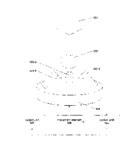
With reference to Figure 1, a device for determining a positioning error of a
CNC machine,
more specifically of a tool head 101 thereof, equipped with a calibration
element 102
CA 02807204 2015-02-19
17b
comprises at least one sensor 103, a control unit 105, and a movement element
106. The
device may further comprise a support base 104 and/or an output unit 107.
Alternatively,
the CNC machine may comprise a machine table equipped with a calibration
element 102.
The machine tool head 101 represents an interface between the CNC machine and
a tool,
wherein the tool may be replaceable. The tool can be a tool for shaping, e.g.
cutting,
milling, drilling, or for measuring and/or testing.
CA 02807204 2013-02-25
18
The calibration element 102 may be a an element explicitly used for
determining a
positioning error and/or otherwise calibrating the CNC tool head, or the
calibration
element 102 may be the tool itself. The former is preferable because the shape
of a tool
may make it difficult to determine a reliable positioning error of the tool
head 101. The
latter may be advantageous if the tool is not removable or difficult to remove
from the tool
head 101. In the present example the calibration element 102 has a shape of a
ball which
is connected to the tool head via a cylindrical element. This ball 102 is
preferably formed
of a hard material, like metal. The ball 102 may be solid or hollow.
The number of sensors 103 may be one, two, three, or more than three. In the
present
example, three sensors 103-1, 103-2 and 103-3 are used. The sensors 103 can be
mounted on a support base 104, wherein they may be fixed at the corners of an
imaginary
triangle, in particular, an equilateral triangle on the surface of the support
base 104, or
parallel to the surface. The sensors 103 may also be located on sockets,
pedestals or the
like, which may be fixed to the surface of the support base 104. The sensors
103 may
have a cylindrical portion along a geometric sensor axis. In particular, they
may comprise
a stationary, in particular, non deflectable, portion whose position along the
geometrical
sensor axis is fixed. The sensors may further comprise a portion that is
movable, in
particular, deflectable, along the sensor axis, such as a sensor head. The
sensors 103
may, in particular, be contact point sensors, where the sensor head comprises
a contact
element which is in contact with a point on the surface of the ball 102. More
specifically,
the contact element is in contact with the point on the surface of the ball
102 and on the
sensor axis which is closest to the stationary portion of the sensor 103. The
sensors 103
may be inclined against the surface of the support base 104 by an inclination
angle. The
angle may be the same for each sensor 103, or different. The angle may be in
the range
of 40 to 80 , preferably 50 to 70 , more preferably 55 to 65 . Under a
higher inclination
angle the ball 102 may be better accessible by the sensors 103. In particular,
this permits
and easy positioning of the ball 102 and a collision free movement of the tool
head 101.
The inclination angles of the sensors 103 may be chosen so that the mutual
angles
between the axes of the sensors 103 are at least 90 . The sensors 103 may be
arranged
to mutually point at the center of a ball 102. The three sensor axes of the
sensors 103
may form a mutual angle of at least 90 . The support base 104 may comprise a
cylindrical
portion. Moreover, the support base 104 may comprise socket, pedestals or the
like, for
mounting the sensors 103. The support base 104 can also comprise adjustment
means
CA 02807204 2013-02-25
19
for adjusting the height and/or lateral position of the sensors 103, and/or
fixing means for
fixing the height and/or lateral position of the sensors.
The control unit 105 may comprise processing means for processing data
received from
the sensors 103 and/or data received otherwise. The control unit 105 may
further
comprise storage means for caching or storing data. The storage means may
include
volatile memory and/or persistent memory. Information representing the
geometrical
layout of the sensors 103, for example, the spatial orientation of their
sensor axes, may be
saved in the memory. The control unit 105 may comprise an input interface for
receiving
data, in particular, sensor data form the sensors 103. The input interface may
include a
plurality of entries. In particular, the sensors 103 may be connected to the
input interface
separately. The sensors 103 may be connected to the input interface by wired
connection
and/or wireless connection. The input interface may also serve for inputting
instructions
into the control unit 105 and/or updating the control unit 105. The control
unit 105 may
further comprise an output interface for outputting data. The output interface
may be
connected to the movement element 106. This connection may be a wired
connection
and/or a wireless connection. The output interface may be further connected to
an output
unit 107. This connection may also be a wired connection and/or a wireless
connection.
The movement element 106 may comprise one, two, three, or more than three
motors,
preferably electro-motors. In particular, the movement element 106 may
comprise three
motors which are configured to translate the support base 104 along each of
the three
coordinate axes x, y, and z of a Cartesian coordinate system. The three
different
translations can be controlled by addressing the three motors separately. The
three
motors may be connected to the control unit 105, in particular, to an output
interface
thereof, separately or collectively. The movement element 106 may be fixed to
the
sensors 103 directly and/or to the support base 104.
The output unit 107 may comprise a display, a printer, a transmitter, and/or a
storage
device, and/or be connected to a display, a printer, a transmitter, and/or a
storage device.
The output unit 107 may also be connectable to the control of the CNC machine.
The
output device 107 may be connected to the control unit 105, in particular, the
output
interface thereof.
CA 02807204 2013-02-25
In operation of the device at least one of the sensors 103, preferable each of
the sensors
103, outputs sensor data while the ball 102 is in a given position. That is,
the sensor data
represents the current position of the ball 102, without necessarily
determining the actual
position of the ball 102. The sensor data is then transferred to the control
unit 105, in
5 particular, to an input interface thereof.
The control unit 105 receives the sensor data from the sensors 103, in
particular, via an
input interface. The control unit 105, in particular, processing means
thereof, determine if
the sensor data satisfies certain conditions. In particular, the control unit
105 may examine
if the difference, in particular, the absolute difference, between sensor data
taken at two
10 different times falls below a threshold value. The control unit 105, in
particular, processing
means thereof, may determine movement data from the sensor data. The movement
data
and/or the sensor data may be cached and/or saved within the control unit 105,
in
particular, within storage means thereof. The movement data may comprise three
separate commands for the three motors of the movement element 106. The
control unit
15 105 may transmit the movement data to the movement element 106, in
particular, via an
output interface.
The movement element 106 receives the movement data from the control unit 105,
in
particular, via an output interface thereof. The movement data may comprise
commands
for at least one of the motors. In particular, the movement data may comprise
commands
20 for three motors which are configured to translate the sensors 103
and/or the support
base 104 along the Cartesian axes. The commands for a motor may comprise
instructions
to translate the sensors 103 and/or the support base 104 along the respective
axis in a
forward direction, in a backward direction, to reverse the translation, and/or
to stop the
translation. The commands for a motor may further comprise instructions to
translate the
sensor 103 and/or the support base 104 with a certain velocity and/or for a
certain
distance.
After the movement element 106 has moved the sensors 103 and/or the support
base 104
according to the movement data output by the control unit 105, the sensors 103
output
new sensor data. The control unit 105, in particular, the input interface
thereof, receives
the new sensor data from the sensors 103 and compares the difference, in
particular, the
absolute difference, between the new sensor data and previous sensor data, in
particular,
sensor data representing an initial position of the ball 102, with a threshold
value. If the
CA 02807204 2013-02-25
21
threshold value is not met, new movement data is determined and output to the
movement element 106. If the threshold value is met, the control unit 105, in
particular,
the processing means thereof, determines a positioning error of the tool head
from the
cached and/or stored movement data. In a Cartesian coordinate system, the
positioning
error (Dx, Dy, Dz) may be the sum of the movement data corresponding to the
movements that were necessary to move the sensors 103 and/or the support base
104 in
order to meet the threshold value.
The control unit 105 may output the positioning error to the output unit 107.
The output
unit 107 may display, print, transmit, and/or save the positioning error. The
output unit 107
may also input the positioning error into the control of the CNC machine.
The sensors 103, the support base 104, the control unit 105, the movement
element 106,
and/or the output unit 107 may be separate units and/or elements, or may be
part of the
same unit and/or element of the device.
With reference to Figure 2A, a method for determining a positioning error of a
tool head of
a CNC machine comprises the steps of reading first sensor data 210, moving the
tool
head 220, reading current sensor data 230, determining the difference between
the first
and current sensor data 240, checking if a threshold value is met 250, and in
response to
the checking 250, determining a compensation direction 260 and moving the
sensor in the
compensation direction 270, or determining a positioning error 280.
In step 210, first sensor data S(to), that is, sensor data at a time to, is
read. The first sensor
data represents the first position of the calibration element 102 which is
connected to the
tool head 101. The first position corresponds to an initial position of the
calibration
element 102, that is, before the tool head 101 is moved in order to determine
a positioning
error thereof. The first position is known to the control of the CNC machine
but unknown
to the control unit 105. The CNC control may operate in Cartesian coordinates
and set the
first position to (0, 0, 0), wherein the first position may correspond to a
pre-deterrnined
reference point on or in the calibration element 102, in particular, the
center of a ball. It is,
however, not necessary for the control unit 105 to determine the first
position. In the case
of three sensors 103-1 to 103-3, the first sensor data S(to) comprises first
sensor data
SI(to), S2(t0), and S3(t0) of the sensors 103-1, 103-2, and 103-2,
respectively. Each of the
sensor data Si(to), S2(t0), and S3(t0) may have components with respect to a
pre-
CA 02807204 2013-02-25
22
determined coordinate system. If Cartesian coordinates are used, the first
sensor data
S/(to) of the sensor 103-1 may have components S,,x(to), SI,y(to), and
SI,z(t0) with respect
to the Cartesian coordinate axes x, y, and z. Similarly, S2(t0) and S3(t0) may
have
components S2,x(t0), S2,y(t0), Szz(to), S3(t0), S3,y(t0), and S3,2(t0). The
Cartesian components
of the first sensor data may be determined from the known direction of the
sensors, that
is, the direction of the geometrical sensor axis, by trigonometric
computations, as known
in the art. However, in embodiments of the present invention it may be
unnecessary to
determine the Cartesian components of the first sensor data.
In step 220, the CNC is operated to move the tool head 101 so that the
calibration
element 102 remains in a theoretically fixed position. That is, according to
the CNC control
this calibration movement does not change the position of the reference point
of the
calibration element 102. The calibration element 102 itself may however move.
In
particular, if the calibration element 102 comprises a ball whose center is
the reference
point, the calibration movement leaves the center of the ball at the fixed
position, while the
ball may still rotate about any axis through its center. In other words, the
CNC assumes
that after the calibration movement the reference point is still at the first
position, e.g. (0, 0,
0). Due to a positioning error of the CNC machine, in particular, of the tool
head, the
calibration element may however be at a second position which differs from the
first
position. If Cartesian coordinates x, y and z are used, said second position
may be
expressed as (Dx, Dy, Dz). This second position is known neither to the
control of the
CNC machine, which still assumes the position (0, 0, 0) instead of (Dx, Dy,
Dz), nor by the
control unit 105. It is an object of the present method to determine Dx, Dy,
and Dz.
In step 230, current sensor data S(t,), that is, sensor data at a time t, >
to, is read. If the
time t, corresponds to a time t, > to before the sensors have been moved, the
current
sensor data S(t1) is the second sensor data representing the second position
of the
calibration element 102, that is, the position of the calibration element 102
after the
calibration movement. The second position of the calibration element 102
corresponds to
the positioning error (Dx, Dy, Dz) of the tool head and is unknown. In the
case of three
sensors 103-1 to 103-3, the current sensor data S(t1) comprises current sensor
data S1(4),
S2(4), and S3(4) of the sensors 103-1, 103-2, and 103-2, respectively. Each of
the sensor
data SAO, S2(t1), and S3(t,) may have components with respect to a pre-
determined
coordinate system. If Cartesian coordinates are used, the first sensor data S-
1(4) of the
CA 02807204 2013-02-25
23
sensor 103-1 may have components S,(ti), Sty(t,), and S1(t1) with respect to
the
Cartesian coordinate axes x, y, and z. Similarly, S2(4) and S3(t1) may have
components
S2,y(t1), Szz(ti), S3,(t1), S3,y(t1), and S3,z(t). The Cartesian components of
the current
sensor data may be determined from the known direction of the sensors, that
is, the
direction of the geometrical sensor axis, by trigonometric computations, as
known in the
art. However, in embodiments of the present invention it may be unnecessary to
determine the Cartesian components of the current sensor data.
In step 240, the current difference D(t) = S(to) ¨ S(t) between the first and
current sensor
data is determined. In the case of three sensors 103-1 to 103-3, the current
difference
D(t) may comprise the three differences D S (to) ¨ S (ti), D2(t) = S2(t0) ¨
S2(0, and
D3(t1) = S3(t0) ¨ S3(4). In particular, the difference D(ti) may have
Cartesian components
D AO, D y(ti), D D
2,x(0 Dzy(ti), D 2,z(ti) D3,x(t), D3,y(t1), and D3,z(t1), wherein D1(t1) =
S,,,(to) ¨ S,,x(ti) and so forth. The Cartesian components of D(ti) may be
determined
directly from the Cartesian components of S(4), or alternatively, by
transforming the
differences NO, D2(ti), and D3(t1) into displacement vectors along the
geometrical axes of
the sensors 103-1, 103-2, and 103-3, respectively, and then determining the
Cartesian
components of the respective displacement vectors from the known direction of
the
sensors, that is, the direction of the geometrical sensor axis, by
trigonometric
computations, as known in the art. However, in embodiments of the present
invention it
may be unnecessary to determine the Cartesian components of the current
difference.
The signs of D
D2(t,), and D3(ti) determine if, at the time ti, the respective sensor is
further deflected or less deflected than at the time to.
In step 250, the current sensor data is read and the difference D(ti), in
particular, the
absolute difference ID(4)1, between the current sensor data and the first
sensor data is
compared to a threshold value T. If the threshold is met, that is, if the
difference D(ti), in
particular, the absolute difference ID(4)1, is less or equal to the threshold
value T, the
positioning error is determined in step 280. If the threshold T is not met,
that is, if the
difference D(ti) , in particular, the absolute difference ID(t1)I, is greater
than the threshold
value T, the method proceeds to step 260. In particular, the threshold value T
may have
Cartesian components Tx, Ty, and T. The threshold condition may then comprise
the
conditions like ID1,x(0 and
similarly for the other components. It also possible to
require different threshold values T1, T2, and T3 for the three sensors 103-1,
103-2, and
CA 02807204 2013-02-25
24
103-3. In this case the threshold condition may comprise conditions like
IDI,x(0 I
and similarly for the other components. Alternatively, the threshold condition
may be
checked for the sum of certain components of the difference D(ti). For
example, the
threshold condition may be evaluated as the sum of the difference Di(t),
D2(4), D3(4) of the
sensors 103-1, 103-2, 103-3 with respect to each Cartesian component
separately. In this
case, the threshold condition may comprise conditions like ID,,x(ti) I +
ID2,x(0 I + ID3,x(0 I
Tõ, and similarly for the other components. In another example, the threshold
condition
may be evaluated as the sum of the Cartesian components Dx(t), Dy(ti), NO of
the
difference with respect to each sensor 103-1, 103-2, 103-3 separately. In this
case, the
threshold condition may comprise the conditions like ID,,x(t) 11:),,y(t) I
+ ID,,z(t)
and similarly for the other sensors. Combinations of the above-described
examples are
also possible. In particular, the threshold condition may comprise the
condition ID,,,(4) I +
IDi,y(t)I + + ID2dc(t1) I + IDzy(t) I + ID2,z(t) I + ID3,x(t1) I +
ID3,0 I + ID3,z(t1)
In step 260, a compensation direction is determined. This determination can be
based on
the differences Di(ti), D2(0, D3(t1), or on their Cartesian components
Di,x(ti), Di,z(t),
D2,(0, D2,y(t1), D2,z(t1), D3,x(t), D3,Y(t), and D3,z(t). The compensation
direction may be
represented by a velocity vector V(4) =
Vy(ti), V2(0), wherein the components Vx(ti),
Vy(t), and V(t1) represent the velocities along the x-axis, y-axis, and z-
axis, respectively,
with which the sensors will be moved in step 270. Here, the signs of Vx(ti),
Vy(t), and V(t1)
determine the direction of the movement along the respective axis, that is, a
forward or
backward translation, whereas their absolute value determines the speed of the
translation along the respective axis. The velocity components Võ(t), Vy(ti),
WO may be
determined from the differences D/(ti), D2(t), D3(0 as follows:
V(t1) = K1 Di(ti) + = D2(t1) + K3,, = D3(0,
V(t1) = Kty= Di(ti) + K2,3, = D2(t1) + K3,3, = D3(0,
V(ti) = K1,, = NO + Kzz = D2(0 + K3,z = D3(4),
wherein the kinematic factors K are the relation between the compensation
direction and
the sensor movement. The factors K may be constant. In particular, the factor
K of a
sensor is constant when the spatial orientation of its sensor axis is fixed.
Moreover, the
factors K may be known, or can be determined as follows:
CA 02807204 2013-02-25
Kt x= A = D1,x(0/ NO; Kt y= A = D1,y(4) / Di(ti); Kt z= A D1,2(0 I
NO;
Kzx= B D2,x(0/ DA); Kzy= B = Dzy(t,)/ D2(ti); Kzz = B = D2( t1) I
D2(ti);
K3,x = C = D3,x(t1) I D3(t1); K3,y = C = D3,y(t1) I D3(ti); K3,z = C =
D3,z (t) I D3(t1);
wherein A, B and C are scale factors related to the constructive solution of
the kinematic
5 system that moves the sensors 103. In particular, A, B and C may
represent scale factors
which the control unit 105 applies when computing the movement data. This may
be
advantageous if the sensors 103-1, 103-2, 103-3 have different gains. The
scale factors
A, B and C may be the same or different. The kinematic factors, for example
Kl, may
comprise weight factors Di,x(ti)/ NO, Di,y(t)/ D1(0, and D1(t1) / Di(t),
representing the
10 relative contribution of a difference component Dtx(t,), Di,y(ti), and
D1(ti) to the overall
difference Di(ti) of the sensor 103-1, and likewise for the other sensors.
This ensures that
the compensation direction V(ti), as determined above, points in a direction
corresponding
to the relative highest overall sensor difference and thereby is closest to
the actual
displacement of the ball 102 due to a positioning error of the tool head 101.
If the K factors
15 are known, a determination of the Cartesian components of the sensor
data S(to), S(ti)
and/or D(ti) can be omitted. Alternatively, the K factors may be obtained by
employing a
reference measurement, for example, the K factors can be obtained from the
first sensor
data, i.e. K1,),= A = S-00)1 SA) etc. A determination of the Cartesian
components of S(ti)
and/or D(t) can then be omitted.
20 In step 270, the sensors 103-1, 103-2, 103-3 and/or the sensor base 104
are moved
according to the velocity vector V(ti) = (V,(4), Vy(t), V,(4)). That is, the
sensors 103-1, 103-
2, 103-3 and/or the sensor base (104) are translated along the x-axis with a
velocity Vx(ti),
along the y-axis with a velocity Vy(ti), and along the z-axis with a velocity
V(f). This results
in a movement into the compensation direction which was determined in step 260
and,
25 thereby, partially or fully compensates the difference D(ti). In the
case when the movement
element 106 comprises three motors which are configured to translate the
sensors 103-1,
103-2, 103-3 and/or the sensor base 104 along the three Cartesian axes,
respectively, the
velocity components Vx(ti), Vy(ti), and V(t1) may be transformed into
respective control
data indicating a forward/backward translation with a respective speed, and
directly input
into the respective motors.
CA 02807204 2013-02-25
26
The method then jumps back to step 230 where new current sensor data S(t1+1)
is read at
a time t,+1 > tõ and a new difference D(t1+1) = S(to) ¨ S(t1.1) is determined
in step 240. Due
to the fact that the kinematic factors K in the compensation direction V(t1)
comprise weight
factors, as described in step 260, the new difference D(t,+1) will be smaller
than the
preceding difference D(t,), that is, ID(t,+.1)1 < ID(4)1. Therefore, the
process converges in
every loop. In step 250, it is checked if the difference D(t,.+1) meets the
threshold value T. If
the threshold value is met, the method proceeds to step 280. If the threshold
value is not
met, a compensation direction V(t,+,) is determined from the difference
D(t1+.1) in step 260,
and the sensors 103 and/or base 104 are moved accordingly. The difference At =
t,+1¨ t, is
called takt time and can, for example, be 1 ms. The takt time At is preferably
a constant, in
particular, a pre-settable constant. However, it is also possible that the
takt time At is
variable.
In step 280, the positioning error is determined based on the movements of the
sensors
103 that were necessary to meet the threshold in step 250. The positioning
error may be
determined by superposing all movement data, starting with the sensor movement
after
reading the second sensor data. The Cartesian components (Dx, Dy, Dz) of the
positioning error may be obtained by adding all components of the movement
data. As an
example, if n steps were necessary to meet the threshold value, that is, ID(t)
T is
satisfied, the positioning error may be determined as follows:
Dx = (101) + + Vx(tn-4) = At,
Dy = (Vy(ti) + + Vy(t1)) = At,
Dz = (Vz(ti) + + Vz(tn_1)) = Lt.
Alternatively, a value C(ti) = (Cõ(ti), Cy(ti), C,(4)) = (Vx(ti) = At, V(t1) =
At, WO = At) indicating
the compensation movement may be computed and stored in every loop, for
example in
step 260. Then, for the above-mentioned example, the positioning error may be
determined as follows:
Dx = C(t1) + + Cx(tr,_1), Dy = Cy(t1) + + Cy(t,4),
Dz = C(t1) + + Cz(t,,_1).
CA 02807204 2013-02-25
27
Alternatively, the value C(t) indicating the compensation movement may be
determined
recursively, that is, C(t) = C(to) + V(t1) = Lt, in every loop, for example in
step 260. Then,
for the above-mentioned example, the positioning error may be determined as
Dx = Cx(tn-i), Dy = Cy(tn_1), Dz= Cz(tn_1).
Since the positioning error is determined from data corresponding to all
movements of the
sensors 103-1, 103-2, 103-3 which were necessary to meet the threshold
condition, the
sensor values Si, S2, and S3 need not be very precise. In fact, the method
will work as
long as, at least at some point t, the differences converge, that is ID(t,,I)I
< !DWI holds for
all t,> t until the threshold condition is met. This way, even detrimental
influences, like jolts
or vibrations which may break the convergence temporarily, will not affect the
result of the
method.
Figure 2B illustrates the position of the calibration element 102 and the
deflection of the
sensors 103 in the case of two sensors 103-1 and 103-2 in two dimensions. A
generalization to the case of three or more sensors is obvious. A
generalization to the
case of two sensors in three dimensions is also obvious.
In step 210, the calibration element 102 is in its first position, say (0, 0),
and the sensors
103-1 and 103-2 provide first sensor data corresponding to the first position
of the
calibration element 102.
In step 220, the calibration element 102 is moved as discussed hereinbefore.
In particular,
according to the CNC control, the calibration element 102 is in the same
position as in
step 210, that is, at (0, 0). Due to a positioning error of the CNC machine,
however, the
calibration element is now at a point (Dx, Dy).
In step 230, second sensor data is read from the sensors 103-1 and 103-2 and,
in step
240, the differences D1 and D2 between the first and second sensor data of the
sensors
103-1, and 103-2, respectively, is determined. The differences DI and D2
represent the
displacement vectors of the contact elements of the sensors 103-1, 103-2,
respectively.
The Cartesian components D1,D1,y, Dzx and Dzy of D1 and 02 are depicted in
Fig. 2C.
However, a determination of D,,,,D1,y, Dzx and Day can be omitted if the
spatial
orientations of the sensor axes are fixed, that is, if the directions which
the sensors point
to are not changed during the procedure.
CA 02807204 2013-02-25
28
Fig. 2D illustrates an example of an algorithm for the example with two
sensors 103-1 and
103-2. From the stored first sensor values S/(to), S2(t0) and the current
sensor values
SA), S2(t1) the differences D1(t1) and D2(4) are computed for the sensors 103-
1 and 103-2,
respectively, as described hereinbefore. Then, from the difference Di(t,),
D2(t1) and the
known factors K1,,, Kzx the x-component V(t1) of the velocity vector V(t,) is
determined as
V(t1) = Kl,x = DA + Kzx = D2(t,), and, analogously, from the difference
Di(t,), D2(4) and the
factors Kly, Kzy the y-component V(t1) of the velocity vector V(t1) is
determined as V y(t =
Kly = Di(t) + K2y = D2(t1). Then, in this loop, that is, for the duration of
the takt time At, a first
motor configured to translate the base 104 along the x-axis will be operated
to translate
the base 104 along the x-axis with the velocity Vx(t,), and a second motor
configured to
translate the base 104 along the y-axis will be operated to translate the base
104 along
the y-axis with the velocity Vy(ti), wherein the signs of V(t1) and Vy(t,)
determine a forward
or backward translation along the respective axis, and the absolute values of
V(t1) and
V(t1) determine the speed of the respective forward/backward translation.