Note: Descriptions are shown in the official language in which they were submitted.
CA 02807455 2013-02-04
WO 2012/025898 PCT/1B2011/053730
1
METHOD FOR FORMING A PACKAGE, A PACKAGE AND A PACKAGE
BLANK
Field of the invention
The invention relates to a method for forming a package, wherein the
package is moulded from a cardboard blank in such a manner that a margin
area of the blank surrounding a middle portion of the blank is bent upwards to
form side walls of the package while the middle portion forms the bottom of
the package. The invention further relates to a package and a package blank
that can be used for forming said package.
Background of the invention
A commonly used package for keeping food is a so-called tray
package. The tray package is often closed hermetically with a lid. In order to
attach the lid to the package, the edge of the package must be equipped with
a horizontal rim or edge flange extending from the upper end of the side walls
and encircling the package. The upper surface of this flange normally
comprises a suitable coating, by means of which the lid can be attached to
the package tightly. Examples of food packages of this type, package
materials used therein, and methods for forming packages are disclosed,
inter atia, in documents WO 03/033258, EP 1 289 856, WO 00/21854, US
5 425 972, WO 03/078012 (corresponding US application 2004/0262322),
W02007/036598 and W02009/074721.
The above-described tray package is normally formed of a flat blank
by pressing it to shape in a mould. The starting material is in a flat shape,
that is, extending in one single plane before it is processed by mechanical
deforming in the moulding operation to a tray package. Cardboard materials,
which are commonly used for such trays, have a sort of memory effect which
tend to restore the package tray just formed back to the original flat shape
by
bending the side walls outwards. Even though the horizontal edge flange or
rim stiffens the structure to some extent, there may be slight deformation,
called "warping", in the final package. This shows as a slightly convex shape
of the upper surface of the rim.
81594153
2
Apart from being a visual defect, the curved shape of the rim may give
technical problems during sealing of the lid to the tray package.
W02009/074721 describes a tray package which has a plastic flange
joined to the upper edge of the side walls of a cardboard tray by Injection
moulding. The rim made in this way makes the tray rigid and enables easier
sealing of the lid. However some plastic materials may shrink a little when
solidifying in comparison to the cardboard material, which creates internal
forces and consequently curving of the rim.
There is thus a need for a moulded package which overcomes the
above mentioned problem with curving of the rim, i.e. warping.
Summary of the invention
It is an object of the invention to provide a method for forming a
package by moulding of a flat blank, which package will have an improved
shape, i.e. a minimally distorted shape. It is also an object of the present
invention to provide a package with improved shape. Another object with the
present invention Is to provide a package blank that can be used in the
manufacture of a package with improved shape as a result.
The present invention relates to a method for forming a
package from a cardboard'blank said blank comprises a margin area
surrounding a middle portion, the package is moulded from the cardboard
blank, so that the margin area is bent upwards forming side walls of the
package while the middle portion forms the bottom of the package, wherein
the blank prior to moulding is provided with at least one area of reduced
bending stiffness being located around the middle portion of the blank, and
the at least one area of reduced bending stiffness is being located in a
transition zone, between the side walls and the bottom, where the blank is
deformed due to moulding.
The at least one area of reduced bending stiffness is preferably
located at a distance from an outer edge of the blank. The transition zone
where the at least one area is being located, is the bended area between the
CA 2807455 2017-11-06
CA 02807455 2013-02-04
WO 2012/025898
PCT/1B2011/053730
3
side walls and the bottom. The at least one area of reduced bending stiffness
is thus preferably located in the bended area between the side walls and the
bottom and the area preferably extend parallelly to the running direction of
the bend.
Thus, the at least one area of reduced bending stiffness will be
situated in the moulded package in the area where the blank material is
deformed due to moulding and is subjected to internal stresses which are
caused by the tendency of the margin area of the moulded package to return
to its original state. Providing the blank with at least one area of reduced
bending stiffness will release the internal stress of the formed package.
It is preferred to provide the package with more than one area of
reduced bending stiffness, preferably two, three, four or even more areas.
The number of areas depends on the shape of the formed package and on
how high the internal stress of the package is. The areas are preferably
separated from each other.
By creating areas of reduced bending stiffness in those places of the
blank which in the finished tray-shaped package will be in the transition zone
between the bottom and side walls (i.e. areas where the blank material is
bent in the forming process), it is possible to release the internal stresses
which build up because of the above-mentioned memory effect of cardboard
material and shrinkage of the rim. The deformation of the package can in this
way be decreased or totally eliminated. These areas can be elongated areas
of predetermined width that run parallelly to the straight sides of the blank.
In
a blank with general rectangular shape there is preferably four such areas:
two in parallel with the shorter sides and two in parallel with the longer
sides.
In practice the said areas can be made weaker by making the areas
thinner compared with the rest of the blank material on their both sides. This
can be performed by creasing, which reduces the thickness of the blank
material. Creasing is an operation where the cardboard material is locally
pressed to be flattened so that the board layers are separated and bending
resistance decreased.
CA 02807455 2013-02-04
WO 2012/025898 PCT/1B2011/053730
4
The areas of reduced bending stiffness do not by themselves cause
bending or folding of the blank material during the moulding operation, but
they, together with the rest of the blank material, conform to the bent shapes
determined by the forming tool, and remain in these shapes as the areas will
relieve the internal stresses. The width of these areas perpendicularly to the
bending direction can be over 1 mm, preferably over 2 mm, and especially in
the range of 2.5 ¨ 4.0 mm. For example, by using multiple parallel creasing
blades, a desired width of the area can be achieved. Narrow areas of
reduced bending stiffness, which have the width of a conventional crease
(around 0.7 mm) normally used for forming folds in cardboard material along
predetermined lines, are not usually able to release internal stresses of the
package in a satisfied way. However, the size of the area with reduced
bending stiffness also depends on the size of the package. It might be
sufficient to provide small packages with areas of reduced bending stiffness
of below 1 mm, for example around 0.7 mm.
The package may also be provided with a horizontal edge flange or
rim, being formed on the upper edge of the sidewalls of the package wherein
the flange is made from a different material than the cardboard blank,
preferably from plastic material.
The invention further relates to a package wherein the package is
formed of a blank comprising at least one area of reduced bending stiffness
in the transition zone between the bottom of the package and the side walls
of the package where the blank material is deformed due to moulding.
The package may also comprises a horizontal edge flange or rim
which is directed from the upper edge of the sidewalls outwards,
approximately in a plane parallel with the original plane of the blank. This
edge flange or rim can be made of the same cardboard blank material as the
rest of the package in the moulding operation. According to an advantageous
embodiment, this flange or rim can be made of different material, such as
plastics, and joined to the upper edge of the side walls of the package. The
process of forming a separate plastic flange in a final stage of the moulding
operation by injecting plastic material is described in international
publication
W02009/074721.
81594153
The present invention further relates to a package blank of planar shape
wherein the
blank comprises at least one area of reduced bending stiffness.
The invention further relates to a method for forming a package, wherein the
package is
5 moulded from a cardboard blank, the blank having straight sides and
rounded corners, the
blank comprising a margin area surrounding a middle portion, wherein the
margin area is bent
upwards to form side walls of the package while the middle portion forms the
bottom of the
package, comprising prior to moulding, providing the blank with at least two
discontinuous
areas of reduced bending stiffness compared to a bending stiffness of the
middle portion, the at
least two discontinuous areas of reduced bending stiffness being located
around the middle
portion of the blank, wherein the at least two discontinuous areas of reduced
bending stiffness
are formed as elongated areas that run parallel to the straight sides of the
blank and are
separated by at least one corner section and wherein the at least one corner
section does not
have an area of reduced bending stiffness, and molding the package from the
blank so that the
at least two discontinuous areas of reduced bending stiffness are located in a
transition zone
between the side walls and the bottom, where the blank is deformed due to
moulding.
The invention further relates to a package comprising a cardboard blank having
a
bottom and side walls extending upward from the bottom, the blank having
straight sides and
rounded corners, and at least two discontinuous areas of reduced bending
stiffness compared
to a bending stiffness of the bottom, the at least two discontinuous areas of
reduced bending
stiffness being located in a transition zone between the bottom and side walls
of the package,
wherein the at least two discontinuous areas of reduced bending stiffness are
formed as
elongated areas that run parallel to the straight sides of the blank and are
separated by at least
one corner section and wherein the at least one corner section does not have
an area of
reduced bending stiffness, and wherein the blank is deformed due to moulding.
The invention further relates to a package blank of planar shape made of
cardboard,
the blank having straight sides and rounded corners, the blank comprising a
middle portion
and a margin area surrounding the middle portion, wherein the blank comprises
at least two
discontinuous areas of reduced bending stiffness compared to a bending
stiffness of the
middle portion, the at least two discontinuous areas of reduced bending
stiffness being
located around the middle portion of the blank in a transition zone between
the middle
CA 2807455 2017-11-06
81594153
5a
portion and the margin area, wherein the at least two discontinuous areas of
reduced
bending stiffness are formed as elongated areas that run parallel to the
straight sides of the
blank and are separated by at least one corner section and wherein the at
least one corner
section does not have an area of reduced bending stiffness.
Brief description of the drawings
In the following, the invention will be described with reference to the
appended
drawings, in which
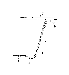
Fig. 1 shows a blank before moulding in top plan view, and
Fig. 2 is a vertical partial cross-section of a package after moulding, along
a plane which is
shown by line II - II in the blank of Fig. 1.
Detailed description of the invention
The term "package" shall in this context mean either a closed package or an
open
package capable of taking a product to be packed and the package should be
closable by a
lid or similar closure.
The blank shown in Fig. 1 is a cardboard blank where the cardboard may be
coated
on one side, both sides or it may be uncoated. If the package made of the
blank is for
packaging food products, the coating on the blank may be a barrier material
giving the blank
barrier properties, for example a barrier against liquid, vapor, grease etc.
The coating may
consist of one layer or it can have two or several layers. Coatings used in
cardboard
packaging materials are widely known and they are not discussed in further
detail in this
context.
The blank is of general rectangular shape with successive straight sides and
rounded
corners at its outer edge, which is a widely used shape for tray-type
containers. The blank
has a middle portion 1 which is surrounded by a margin area 2 which is
outwardly limited by
the outer edge of the blank. The corners of the margin area 2 comprise
radially extending
score lines 5, or the like known as such, which will help to form the corners
of the package
during the molding operation.
CA 2807455 2017-11-06
CA 02807455 2013-02-04
WO 2012/025898 PCT/1B2011/053730
6
The moulding operation where the package is formed from the blank is
preferably a compression molding using a press tool which deforms the blank
and urges it to the final shape. The package obtains its final shape when the
cardboard blank is pressed between two mould halves. During this operation
the margin area 2 will be bent upwards from the middle portion 1 which
retains its original orientation and forms the bottom of the package. The
margin area 2 will form the side walls of the package around the bottom,
limiting the inner volume of the package laterally in all directions. Due to
the
moulding operation the transition zone 3 between the middle portion 1 and
the margin area 2 will undergo bending deformation in a direction
perpendicular to the plane of the blank. This zone 3, where the side walls
connect to the bottom, will have a curved shape seen in vertical cross-section
of the package. To reduce or eliminate internal stresses caused by this
deformation, the transition zone 3 contains elongated areas 4 of reduced
bending stiffness. In the blank shown in Fig. 1 there are four such areas 4
around the middle portion 1, two in parallel with the shorter sides of the
blank
and two in parallel with the longer sides of the blank. The areas 4 are of
limited length and separate from each other in the circumferential direction.
They extend in parallel with the straight sections of the short sides and long
sides of the blank, but they do not continue till the curved corner sections,
i.e.
they are discontinuous. By separating the areas of reduced bending stiffness
it is possible to optimize the size, such as length, thickness and width, of
the
areas in a more effective way since the size of each area can be made
different. In this way a more flexible and efficient way of reducing or even
eliminating the deformation of the package can be achieved.
Fig. 2 illustrates the location of the area 4 of reduced bending stiffness
in the moulded package, which is a so called tray-type container. The figure
shows the side wall, the bend between the side wall and the bottom, and part
of the bottom. The area 4 of reduced bending stiffness extends along the
running direction of the bend. The running direction of the bend is the
direction where the cross-section of the bend remains constant and it
corresponds to the direction of the transition zone 3 in the blank. The area 4
is in the bend preferably in an angular position of about 40-50', preferable
about 45 , down from the horizontal, that is, where the radius connecting the
centre of curvature of the bend and the area 4 forms an angle of about 40-
CA 02807455 2013-02-04
WO 2012/025898 PCT/1B2011/053730
7
500 with the horizontal plane on the side of the side wall. However, the said
area 4 has stress relieving effect in cardboard material in all spots where
deformation due to bending of the margin area away from the original plane
of the blank has occurred.
The areas 4 of reduced bending stiffness, which can be designated
"weaker areas", are most conveniently formed by making the blank thinner,
which automatically reduces the bending stiffness compared with the blank
which has original thickness. The area 4 is of predetermined width, preferably
over 1 mm and more preferably over 2 mm. Suitable width of the area is
between 1 ¨ 5 mm, preferably between 2.5 ¨ 4.0 mm, but the area may be
even wider. The width of the area 4 can be fixed for example by choice of the
number of creasing blades that make the blank thinner. By using multiple
parallel creasing blades any desired width of the area 4 can be obtained.
Figure 2 shows also a horizontal edge flange or rim 6 extending
outwardly from the upper edge of the side walls and surrounding the
package. The flange 6 is formed separately from plastic material, for example
thermoplastic polymer. Even though the flange 6 is not the same material as
the cardboard blank, it can be fixed to the tray-type container during the
same moulding operation where the container is formed. The flange can be
made by injecting the material to a moulding cavity that is opened in a
suitable moment in the press tool, as explained in the international
publication WO 2009/074721, A lid 7 that is sealed to the upper surface of
the flange 6 to close the package is designated by broken lines. The lid 7 is
preferably made of cardboard whose lower surface has been coated with a
material that is compatible with the material of the flange 6, for example for
sealing the lid tightly and/or for allowing reclosability. The lid 7 may also
be a
plastic film comprising one or more layers and sealed to the upper surface of
the flange 6. Such a film may be transparent so that the content of the
package can be viewed without opening the package. It is also possible that
the lid 7, irrespective of its material, is attached to the flange 6
mechanically
only.
Even if the above-described package is particularly well suited for
packaging of food in a tight manner which prevents diffusion of substances
CA 02807455 2013-02-04
WO 2012/025898 PCT/1B2011/053730
8
into and/or out of the closed package, it is also suitable for products other
than food.
The shape of the blank and the resulting package need not necessary
be rectangular. The shape can also be square where all sides have equal
lengths. The shapes of other polygons are also possible. It is also possible
that the blank and the package formed thereof has an oval shape.
The at least one area of reduced bending stiffness can also go
uninterruptedly around the entire blank, surrounding its middle portion. Since
the compression or forming of the area of reduced bending stiffness is
preferably done at the same time as the forming of the score lines in the
corner, it might not be possible to provide the corners with the areas of
reduced bending stiffness in one process step. However, if the creases are
formed in two steps it is possible to provide also the corners, i.e. the area
with radially extended score lines, with areas of reduced bending stiffness.
The area/areas of reduced bending stiffness can be located either on
the inside or on the outside of the package, because they will have similar
effect on both locations. Thus, creasing can be performed on either side of
the blank. In relation to Fig. 1, this means that the areas could be on the
top
side or on the bottom side of the blank. Furthermore, the invention can be
applied both in packages made entirely of cardboard material and packages
having a plastic rim described above. The invention is especially
advantageous in cases where the shrinking of the plastic material of the rim
in relation to the cardboard material causes the above-mentioned slight
deformation problems in the moulded package.
It is contemplated that there are numerous modifications of the
embodiments described herein, which are still within the scope of the
invention as defined by the appended claims.