Note: Descriptions are shown in the official language in which they were submitted.
WO 2012/018394 CA 02807469 2013-02-04
PCT/US2011/001370
METHOD AND APPARATUS FOR COPRODUCTION OF PIG IRON AND HIGH QUALITY SYNGAS
CROSS REFERENCE TO RELATED APPLICATION
This application claims the benefit of U.S. provisional application no.
61/496,733 filed on
June 14, 2011; no. 61/393,521 filed on October 15, 2010; and no. 61/400,850
filed on August 3,
2010, the content of which is hereby incorporated by reference.
BACKGROUND OF THE INVENTION
This invention relates to a process and apparatus for reducing and smelting
iron ore and
generating syngas of a controlled high quality composition.
Petroleum has been regarded as the center of any future energy crisis. To
assure the
future supply of energy, technologies for converting carbon containing
materials such as biomass
and coal to liquid fuels have long been investigated due to their vast
abundance. Gasification of
biomass and coal to a gas product rich in carbon monoxide and hydrogen is
typically the first
step of the conversion. The conventional gasification process involves the
partial oxidation of the
carbon containing materials with oxygen separated from the air. The reactor is
commonly an
autoclave that can facilitate the high pressure and high temperature
reactions.
Both the air separator for oxygen production and the high pressure-high
temperature
reactor involve high capital and operation costs, and thus make such
gasification a very
expensive process.
The gasification product usually contains 10%-30% carbon dioxide in addition
to the
carbon monoxide and hydrogen. Carbon dioxide needs to be removed to yield a
syngas product
that is almost entirely made up of carbon monoxide and hydrogen. Syngas is the
starting material
for many chemical reactions that lead to the production of many useful
chemical compounds
such as gasoline, diesel, plastics, fertilizers, and other substances.
1
WO 2012/018394 CA 02807469 2013-02-04PCT/US2011/001370
The current syngas generation technologies typically rely on combustion of a
fuel to heat
materials.
US patent 7,381,230 discloses a process for the production of syngas from a
feed stream
comprising a hydrocarbon containing gas and an oxygen containing gas.
US patent 7,452,392 discloses a process for the conversion of organic waste
material
such as municipal trash, sewage, post-consumer refuse, and biomass into
syngas.
US patent 7,717,971 discloses a process for the production of syngas from a
hydrocarbon
feed stock using a steam reforming system.
US patent 7,736,400 discloses a method for producing a gas comprising
substantial
amounts of methane, hydrogen and/or carbon monoxide from a solid carbonaceous
material and
an oxygen carrier using a non-thermal plasma reactor at a temperature in a
range of about 300 C
to 700 C.
US patent 7,658,155 discloses a process for treatment of waste by gasification
in the
presence of oxygen and steam or pyrolysis to produce an offgas and treating
the offgas in a
separated plasma unit in the presence of oxygen and steam.
US patent application 20080277265 discloses a process for reformulating an
initial gas
into a reformulated gas having designed for characteristics by applying a gas
energizing field
sufficient to reformulate the majority of the gaseous molecules into their
constituents and
promoting efficient process acceleration for the reformulation of the
constituents into a
reformulated gas of designed for characteristics.
Published US patent application 20080069765 discloses a method for catalytic
partial
oxidation of hydrocarbons with an oxygen containing gas to produce syngas.
2
WO 2012/018394 CA 02807469 2013-02-04PCT/US2011/001370
Published US patent application 20060228294 discloses a method for producing
syngas
using a molten metal bath by injecting feed materials directly into the molten
metal bath,
injecting oxygen and steam into the vessel enclosing the molten metal bath,
removing produced
syngas continuously, and removing molten metal and vitreous material
periodically.
Published US patent application 20070102279 discloses a method for reducing
organic
compounds into carbon and gases by microwave energy.
Published US patent application 20060124445 discloses an electrical heating
reactor for
hydrocarbon gas reforming by passing the hydrocarbon gas and an oxidant gas
through a porous
but electrically conductive lining material connected between two electrodes.
An electrical
source is used to power the electrodes and resulting in generation of an
electronic flux in the
conductive lining and heating the lining.
Published US patent application 20050191233 discloses a process for catalytic
partial
oxidation of hydrocarbons to produce a syngas.
The above patents or published patent applications teach only syngas
productions from
carbonaceous or organic materials, and do not describe co-production of syngas
and metal.
US patent 7,674,443 discloses an integrated process for gasifying a
carbonaceous source
using steam and oxygen gas and producing nanoscale metallurgical powder
through
carbochlorination using chlorine gas as a reactant and carbon monoxide as an
oxygen sink.
US published patent application 2002177745 discloses a method for processing
waste
materials into more desirable products by the expedient of breaking down these
materials into
their stable molecular constituents and reforming them into more desirable
substances in two
chambers with microwave radiation, lasers, masers, and/or ultrasonic energy.
3
WO 2012/018394 CA 02807469 2013-02-04 PCT/US2011/001370
Currently, steels are produced by two types of operations: integrated mills
and minimills.
In the integrated mill, sintered iron ore pellets, coke and lime are charged
into a blast furnace
(BF). Air is blown at high speed to combust the coke to generate carbon
monoxide and heat.
Sintered iron ore pellets are reduced to hot metal by carbon monoxide and
melted to form liquid
pig iron. The liquid iron is then sent to a basic oxygen furnace (BOF) where
pure oxygen is
blown into the liquid iron to remove excessive carbon and convert the iron
into steel. The
fundamental problems associated with this production route are the needs for
coke and
intensified combustions. Coke making is one of the most polluting of
industrial processes and
intensified combustion generates a great amount dust and waste lot of energy
in the exhaust
gases.
Minimills employ electric arc furnaces (EAF) to melt steel scrap and/or DRI
(direct
reduced iron) and produce generally lower quality steel. Minimills
traditionally enjoyed an
abundant supply of steel scrap. However, recent rapid economic growth of major
developing
countries has caused shortage of steel scrap supply.
Currently, DRI is produced by three types of processes: gas/shaft, gas/fluid
bed, and
coal/RHF (rotary hearth furnace) or RKF (rotary kiln furnace). In a gas/shaft
process such as
Midrex or HYL, iron ore powder is heated and reduced into iron powder in a
shaft with a hot
reducing gas which is derived from reforming natural gas. In a gas/fluid bed
process such as Fior
or FINMET, iron ore powder is heated and reduced into iron powder in a series
of fluidized-bed
reactors with a hot reducing gas which is also derived from reforming natural
gas. In a coal/RHF
or RKF process such as FASTMET or INMETCO, pellets of iron ore and
carbonaceous powders
are heated by combustion of a fuel in a rotary hearth furnace or a rotary
kiln. The carbonaceous
material functions as the reducing agent to reduce the iron ore pellets into
iron sponges. The
4
WO 2012/018394 CA 02807469 2013-02-04 PCT/US2011/001370
gas/shaft process dominates the DRI production at present. The price and
uncertain supply of
natural gas have caused operational difficulties in many DRI plants.
In addition to producing DRI by solid reaction, there are several iron
smelting processes
such as COREX, HIsmelt and Mesabi Nugget which produce molten iron or involve
iron
smelting using coal, natural gas or oil as the combustion fuel or heating
source.
All of the above technologies rely on external heating of the materials
through
conduction, convection and radiation from a heating source.
US patent 4,906,290 discloses a method of drying and heating a mixture of
particulate
ores with an oxygen-containing carbonaceous material using microwave energy to
initiate
reduction reaction of the ores. In this method, solid oxide wastes can be
treated in the same
manner as the particulate ores to recover selected elements.
US patent 6,277,168 discloses a new steelmaking technology based on the use of
microwave energy. This technology can produce DRI, iron or steel from a
mixture, consisting of
iron oxide fines, powdered carbon and fluxing agents. This technology is
projected to eliminate
many current intermediate steelmaking steps, such as coking, sintering, BF
ironmaking, and BOF
steelmaking. In this technology, Zn, Pb, Sn, Cd and Fe bearing by-products
such as BOF sludge
and EAF dust can be treated in a similar manner as iron ore concentrates to
extract valuable
metals.
Published US patent application 2004/70060387 discloses a process for the
reduction of a
metalliferous ore or concentrate using a microwave induced plasma.
PCT/AU88/00437 discloses a method for microwave irradiation of mineral ores
and
concentrates to produce metallic droplets.
5
WO 2012/018394 CA 02807469 2013-02-04 PCT/US2011/001370
All of the above patents and patent applications have no concurrent steel and
gaseous fuel
production.
Steelmaking by-products such as EAF dust and BOF sludge cannot be disposed
directly
because both by-products contain high level of zinc and the highly toxic lead
and cadmium.
Several HTMR (high temperature metal recovery) technologies have been
disclosed to teach the
methods of treating the by-products by heating them with a combustion source
in a reducing
condition in a furnace. The zinc and cadmium exist in the form of oxides which
are be reduced,
volatized, re-oxidized and captured by a bag house connected to the furnace
exhaust. The most
successful of the HTMR technologies is the Waelz kiln process.
US patent application 10/950,260 teaches a method of preheating a mixture of
EAF dust
and a quantity of carbon to between 100 C and 200 C with a conventional
heating method. The
preheated dust is then heated by microwave in a microwave compatible kiln
until zinc in the
preheated dust vaporizes to form a metal vapor and a residue. The zinc vapor
is then condensed
or oxidized and captured by a bag house. The residue is removed from the
microwave kiln and
further heated to form a molten material. The quantity of carbon is determined
by the percentage
of zinc.
There is no syngas produced in the process described in that application.
In published international application no. WO 2008/051356 by the present
inventors,
there is a suggestion of producing syngas after an initial reduction of iron
oxide using microwave
energy and carbon preferably coal as a reducing agent. The syngas is comprised
of CO produced
by a reaction of excess carbon and oxygen released from the iron oxide in
being reduced in a first
microwave heating zone and H2 produced from hydrocarbons and moisture in the
coal in a
6
WO 2012/018394 CA 02807469 2013-02-04PCT/US2011/001370
second zone of heating, both reactions enhanced by the presence of metallic
iron produced by the
reduction of iron oxide.
However, it would be desirable to control the composition of the syngas to
insure a major
H2 component as well as CO to which is easily convertible to liquid fuels such
as gasoline.
It is an object of the present invention to improve the methods and apparatus
described in
PCT WO 2008/051356 by increasing their efficiency and output and to produce a
high quality
syngas able to be easily converted to liquid fuels, and also to include an
ability to control the
composition of such high quality syngas.
SUMMARY OF THE INVENTION
This invention discloses a method using a combined successive microwave
heating and
plasma/electric arc heating in separate zones for several methods which
include co-production of
pig iron and high quality syngas, biomass to liquid production, coal to liquid
production, co-
gasification of biomass and coal, municipal solid waste treatment, waste-to-
energy, EAF (electric
arc furnace) dust and BOF (basic oxygen furnace) sludge process to recover
zinc and iron,
hazardous bottom ash vitrification, and bromine, chlorine and sulfur
removal/recycling.
In the co-production of pig iron and syngas, iron oxide fines are mixed with a
carbon
containing material such as coal or biomass or organic wastes which hold
substantial quantities
volatile hydrocarbons such as methane and also moisture to form a feed
mixture. The feed
mixture is charged into an air tight chamber of reactor in a relatively
shallow thickness with
successive heating in microwave and plasma/electric arc heating zones. The
mixture is initially
quickly heated up to elevated temperatures by microwave irradiation in the
first zone due to its
good microwave absorbing capability. The iron oxide fines are reduced by the
carbon present to
become an electrically conductive mass of partially reduced DRI.
7
WO 2012/018394 CA 02807469 2013-02-04PCT/US2011/001370
The DRI is conveyed to the plasma/electric arc second heating zone in the air
tight
reactor chamber where it is quickly heated to a much higher temperature to
complete the
reduction of the iron oxide in the feed mixture and melt the iron formed
thereby to form pig iron
nuggets. The exhaust gases generated by the microwave heating are constrained
to also pass
through the high temperature plasma/electric arc second heating zone where the
mixture is
heated to a sufficiently high temperature to melt the DRI and to reform,
decompose and/or react
the exhaust gases generated by the first stage of heating, resulting in an off-
gas of a CO and H2
mixture. After cleaning, the off-gas becomes a high quality syngas. The
reactor can be a rotary
hearth, a rotary kiln, a shaft furnace, a conveyer furnace, or a traveling
grate furnace with
combined microwave and plasma/electric arc heating or other microwave assisted
hybrid
heating.
In the conversion of biomass or organic wastes to syngas, the feed material is
shredded to
less than 2", mixed with a microwave absorbing material, and fed into the air
tight reactor
chamber with subsequent successive microwave and plasma/electric arc heating.
The feedstock
is quickly pyrolyzed by microwave heating, resulting in the production of
combustible gases, oil
vapor, steam, and charcoal. The exhaust gases are forced to pass through and
the charcoal travels
to the high temperature plasma/electric arc heating zone to reform, decompose
or react, resulting
in an off-gas of CO and H2 mixture. Additional treatments of the syngas in
small auxiliary
reactors may be carried out. After such treatments and cleaning, the off-gases
are converted to a
high quality syngas suitable for conversion to liquid fuels.
EAF dust and BOF sludge also can be processed using the method of this
invention to
recover Zn and Fe, and produce syngas and a ceramic material. In this
application, EAF dust or
BOF sludge is preferably mixed with a low volatile carbon bearing material to
form a mixture.
8
WO 2012/018394 CA 02807469 2013-02-04PCT/US2011/001370
The mixture is charged into the reactor and heated by microwave irradiation to
elevated
temperatures. Upon heating, zinc oxide in the dust or sludge is reduced,
melted and vaporized
into the exhaust gases. The zinc vapor condenses to form zinc particles in the
reducing
atmosphere. The zinc particles are collected by a bag house. Upon continuous
heating, the
remaining iron oxide in the dust or sludge is reduced to form DRI.
Further heating by a plasma/electric arc heater turns the DRI into pig iron
nuggets. The
exhaust gases after reforming, decomposing and reacting during the heating
plasma/electric arc
and in the presence of the melted iron and carbon at the elevated temperatures
become an off-gas
of CO and H2 mixture. After cleaning, the off-gas becomes a high quality
syngas. Additional
materials can be blended into the dust or sludge to form a feed material for
controlling the slag
composition in order to create a marketable ceramic material.
BRIEF DESCRIPTION OF THE DRAWINGS
The invention is further described with reference to the several views of the
drawings
wherein, without limiting the scope of the claimed invention:
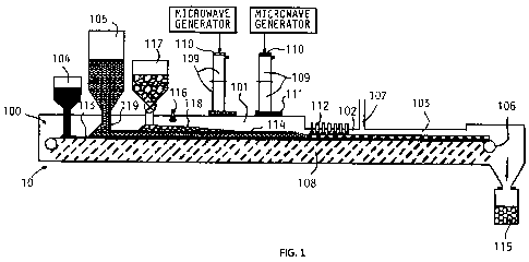
FIG. 1 is a diagrammatical representation of a combination microwave/plasma
arc
furnace suitable for carrying out a process according to the invention.
FIG lA is a diagrammatical view of a variation of the furnace shown in Figure
1.
FIG. 2 is a plan diagrammatical view of a combination microwave plasma arc
rotary
hearth furnace suitable for carrying out the invention.
FIG. 3 is an enlarged cross sectional view of a gas purging waveguide shown in
Figure 1
with a gas blowing, reliable cleaning, and easy replacement window.
FIG. 4 is a diagrammatical representation of an alternative form of a
microwave/plasma
arc furnace.
9
WO 2012/018394 CA 02807469 2013-02-04PCT/US2011/001370
FIG. 5 is a diagrammatic representation of an auxiliary plasma heated gas
reforming/carbon partial oxidation reactor.
FIG. 6 is a diagrammatic representation of an auxiliary induction heated gas
reforming/carbon partial oxidation reactor.
FIG. 7 is a diagrammatic representation of an auxiliary electric directly
heated gas
reforming/carbon partial oxidation reactor.
DETAILED DESCRIPTION
In the practice of this invention, an air tight furnace capable of continuous
operation is
provided, the furnace 10 as depicted in FIG. 1, has a chamber 100 having a
microwave heating
zone 101, a gas constraint plasma/electric arc second heating zone 102, a
cooling zone 103, a
material feeding system comprising of a bottom carbon feeding port 104, a
primary feedstock
feeding port 105, a solid product discharging mechanism 106, a gaseous product
exporting port
107, and a continuous traveling hearth covered with refractory layer 108 of a
thickness
preferably over one half microwave length. Preferably, the furnace has a
rotary hearth 90 having
an OD and an ID to form a microwave/plasma arc rotary hearth furnace 10A as
shown in FIG. 2.
As an alternative, the furnace may be comprised of a microwave heating chamber
and a
separated plasma/electric arc heating chamber which are connected to form an
integrated furnace
as described below.
Microwaves are introduced into the microwave heating zone 101 through
waveguide
segments 109. The segments 109 are connected in an air tight manner to link
each microwave
generator as shown to the heating zone 101 of the chamber 100. Two microwave
transparent
windows 303, 304 (Figure 3) are installed in the integrated piece of the
waveguide, one near the
generator end 110 and one at the entrance 111 to the zone 101. The waveguides
segments 109
10
WO 2012/018394 CA 02807469 2013-02-04PCT/US2011/001370
are purged continuously with an inert gas, CO, H2 or syngas through a port 301
as shown in FIG.
3 to prevent air from getting into the furnace chamber 100 if the window is
broken. Otherwise,
there may be an explosion if air is mixed with the produced syngas at an
elevated temperature.
The surface of the entrance window facing the chamber interior is cleaned
continuously with a
gas, preferably the same waveguide purging gas, introduced through a U turn
mechanism 302.
The entrance window 300 is comprised of two identical halves 303 and 304, and
both are
slidably mounted in a frame, one in the working position and the other 304 in
a cleaning and
replacing position. Each sliding cycle reverses the positions of the two
halves 303, 304 and also
cleans the window halves 303, 304 with a brush 305. The sliding motion can be
driven by an air
cylinder (not shown) and controlled automatically. If damaged, each half
window 303, 304 can
be replaced readily without interrupting the operation. The window cleaning
brush 305 and easy
replacement make the microwave heating suitable to deal with the dusty, humid
and smoky
chamber environment.
To produce pig iron nuggets and high quality syngas, a bottom carbon charging
mechanism 104 is connected to the furnace chamber 100. Multiple, precisely
arrayed plasma
single or twin electrode torches 112 are installed in the plasma/electric arc
heating zone 102,
preferably arranged in multiple rows and multiple columns with arc spaces
between 0.5" and
12.0", preferably 1.0" to 2.0", and of even or gradually descending heights.
The cross sectional
area of the plasma/electric arc heating zone 102 is reduced from the microwave
heating zone 101
to ensure that substantially all of the exhaust gas is rapidly heated by the
ultra high temperature
plasma arcing.
The plasma gas can be H2, CO, syngas, H20 steam, or an inert gas. Optionally
each torch
can use a different plasma gas. The spacing between the ceiling of the
plasma/electric arc heating
11
WO 2012/018394 CA 02807469 2013-02-04PCT/US2011/001370
zone and the top surface of the feedstock layer is between 0.25" and 12",
preferably in the range
between 0.5" to 2.0". The plasma/electric arc heating zone length is
sufficient to form molten pig
iron and complete in-situ reforming, thermal cracking and reaction with
residual carbon with the
exhaust gases to form a high quality syngas.
To isolate the feedstock charging port 105 from the syngas exporting port 107
and
facilitating uni-directional flow of gases to the syngas exporting port 107,
the chamber 101 has at
least one dynamic material curtain 201, 202 and 203 (Figure 2). To facilitate
pig iron nugget
formation, the furnace hearth 90 rotates in a stepped manner. Both stop
durations and rotation
distances are adjustable. Also, the chamber 100 may have a gas injector 204
installed (Figure 2)
with multiple openings immediately after the plasma/electric arcing zone 102
to blow-cut the
molten pig iron and slag into pieces, or installed with a water cooled and
horizontally rotated
shaft with multiple arms to cut molten pig iron and slag into pieces.
In the practice of the invention, iron ore (an iron oxide) is mined, crushed,
ground and
concentrated by a separation process to increase iron content. The
concentrated fine particles of
iron ore, preferably at least finer than 100 mesh, and preferably finer than
325 mesh, are mixed
with fine particles of a carbon containing material preferably at least finer
than 100 mesh,
preferably finer than 200 mesh, such as pulverized coal, and a hydrogen-
containing compounds
either as fine solid particles or as liquid in a certain ratio. Bituminous
coal will typically have
substantial moisture and volatile hydrocarbon content, mostly methane, to
provide a substantial
hydrogen content in the exhaust gases.
The correct ratio of feedstock components is determined by analyzing the iron
oxide
content in the iron ore and the fixed carbon content in the pulverized coal
sufficient to complete
reduction of the iron oxide by the fixed carbon, mixing the above materials in
the ratio being able
12
WO 2012/018394 CA 02807469 2013-02-04PCT/US2011/001370
to remove oxygen completely from the iron oxide and to form iron with carbon
content between
2.06 to 6.67%, preferably around the eutectic 4.3% in order to lower the
melting point of the
iron, and to yield a syngas with the H2/C0 ratio preferably in the range from
0.5 to 3.0,
preferably around 2%. The mixture is used as the feed material in the form of
loose powdered
masses or of agglomerates with a binder.
The carbon particles are charged into the furnace chamber 100, distributed
over the
bottom refractory 108 in a layer 113 of a depth between 0.25" to 2.0",
preferably 0.5" to 1.0"
thick, through the bottom carbon charging mechanism 104. The carbon layer 113
serves as an
insulator between the refractory 108 and the molten pig iron as well as a
microwave receptor.
Next, the feedstock mixture is charged in a 0.5" to 12" layer 114, preferably
around 1.5" thick,
into the air tight chamber over the bottom carbon layer 113. The depth of the
feed mixture layer
114 is established using a sliding gate 119. Three processes happen during the
successive
heatings: iron ore partial reduction in the first zone and, iron smelting, and
in-situ
reforming/thermal cracking/partial oxidation of the exhaust gases and carbon
to form the syngas
composition.
As to the iron ore partial reduction, firstly, microwave energy heats the
layer 114 of the
iron ore and feedstock coal mixture to approximately 800 C in a few minutes.
During microwave
heating, the coal serves as the reducing agent for the iron oxide, and an
auxiliary heating source
via an exothermal oxidation reaction of the carbon and as the hydrogen source
for the syngas
generation. The iron oxide serves as the source of iron for steel production
as well as the source
of oxygen for the carbon partial reaction to form CO which acts as the main
reduction agent. A
distinction over conventional coal gasification, the oxygen comes from iron
oxide (chemical
looping) instead of from pure oxygen produced by an oxygen plant.
13
WO 2012/018394 CA 02807469 2013-02-04PCT/US2011/001370
During the microwave heating, iron ore is quickly partially reduced into
direct reduced
iron (DRI). After DRI is formed, the feed material becomes a poor microwave
absorber due to
the formation of networked metallic iron. The microwave heating is designed to
result in
approximately 50-70% metallization with high heating efficiency..Volatiles in
the coal (primarily
methane, CH4) and steam are also released during the initial heating process.
Next, the iron and carbon content in the feedstock can be controlled to form
the Fe-C
eutectic composition (4.26%C) through the feedstock recipe. At the eutectic
composition, the
melting point of the Fe-C alloy is 1154 C.
Plasma arc heating takes over after the microwave heating to complete the iron
ore
reduction and melt the eutectic or near eutectic Fe-C material (pig iron). The
combination of a
furnace hearth step rotation, or a material advance step travel, with the
arrayed plasma torch
arrangement, the molten pig iron forms nuggets without dead corners. It may
also utilize a gas
injector 204 (Figure 2) to blow-cut or the horizontally rotated shaft with
multiple arms to cut the
molten pig iron and slag into pieces. The ash in the coal and the impurities
in the iron ore form
slag. The slag composition can be adjusted by adding fluxing agents in the
feed to form a slag
suitable for desulphurization and dephosphorization with lower melting point,
lower viscosity,
proper basically, and easy separation from the pig iron nuggets after cooling.
The remaining underlying carbon layer 113 functions as an isolator between the
molten
nuggets and the slag from the refractory base 108 and facilitates discharging
the produced
nuggets and slag from the refractory base through an auger 205 (Figure 2) and
collected in a tank
115 (Figure 1). The produced pig iron nuggets can be used as a feed material
for ferrous
foundries or steelmaking using conventional electric arc furnaces.
14
WO 2012/018394 CA 02807469 2013-02-04PCT/US2011/001370
At 800 C and above, iron functions as a catalyst to promote the transformation
of
methane, other hydrocarbons, water vapor and bio-oil vapor into H2 and CO. The
plasma/electric arc heating zone 102 comprises an in-situ reforming zone 102.
This zone is
constructed by lowering the ceiling of the furnace chamber and reducing the
cross section area of
gas flow to force the gases into better contact with the fresh iron nugget
surfaces.
At elevated temperatures in the carbon enriched microwave reduction zone 101,
which
are required for fast iron ore reduction, most water and CO2 react with carbon
to form H2 and
CO. In the in-situ reforming zone 102 with plasma heating to even higher
temperature, (i.e., the
melting point of the iron) such environment further ensures complete reactions
of residual water
vapor and CO2 with residual carbon, such as layered bottom carbon and for
biomass char, to also
form H2 and CO.
In this technology, the entire heating and reaction process takes place in a
continuous and
enclosed system. Because no air is required for combustion and the process is
controlled by the
Bouduard Equation, only the H2 and CO are generated through in-situ reforming
of exhaust
gases produced by the microwave heating. Thus, a high quality syngas can be
produced. The
biomass composition, moisture level, and the equilibrium phase diagram of iron
oxides, iron,
CO, and CO2 vs. temperature can be used as references to control the off-gas
composition.
Because there is no significant combustion heating, the off-gas is of lower
temperature
and contains less particulate. The off-gas is then passed through a cleaning
system to further cool
down, remove particulates, adjust Hz/CO ratio by water gas shift (WGS),
recover sulfur, and
separate H20 and CO2, becoming a clean syngas. Because there are no steam or
combustion
required, syngas production has fewer problems related to H20 separation and
NO formation.
15
CA 02807469 2013-02-04
WO 2012/018394 PCT/US2011/001370
This syngas can be converted to a gaseous fuel such as gasoline and diesel
using the Fischer-
Tropsch or Mobil process or other chemicals.
Various reactions in the mixture can be written as:
CO2 + C = 2C0 (1)
H20+C=CO+H2 (2)
Fe
H20 CH 4 CO + 3H2
Fe (3)
CO2+ CH 4¨> 2C0 + 2H2 (4)
3Fe203 +H2 = 2Fe304 + H20
(5)
Fe304 +H2 =3Fe0+H20 (6)
Fe0 + H = Fe+ H 20
(7)
3Fe203 CO =2Fe304 CO2 (8)
Fe304 +CO =3Fe0+ CO2
(9)
Fe0+CO=Fe+CO2 (10)
From these equations, we can see that all the oxygen can be supplied by iron
oxide (Eq. 5
to 10) in an air tight microwave reactor. When the temperature is above 1000
C, only CO and H2
can co-exist with carbon (Bouduard Equation) and there will be no CO2 and H20
in existence
(Eq 1 and 2). The volatiles from the biomass will be reformed to CO and H2
during the process
with the presence of the reduced iron (Eq 3 and 4). Therefore, the net
products in the
microwave/plasma reactor would be only iron, CO and H2. This theoretically
achieves a 100%
carbon efficiency versus the 30% in the conventional process. There will be no
need for an
oxygen separator, a steam generator, or high pressure-high temperature reactor
as the
conventional gasification requires, neither the coke nor the environmental
scrubbing system for
the steel production.
In one option, the chamber 100 may have a hydrogen-containing compound
injection port
116 (Figure 1). An additional hydrogen-containing mixture such as H2O and
waste oil is injected
16
WO 2012/018394 CA 02807469 2013-02-04PCT/US2011/001370
into the chamber to increase f12/C0 ratio, to react with the carbon containing
particles and
bottom carbon particles, and increase syngas output.
In a preferred form, the chamber 100 may have a port 117 for charging biomass
or
organic waste. Additional biomass or organic waste pieces are charged into the
chamber in a
layer 118 between 0.25" to 2" thick over the layer 114 of the main feedstock
mixture as a thermal
insulator to reduce heat lost, utilize heat more efficiently, increase syngas
output, and facilitate
carbon reaction with excessive steam and CO2 especially in the plasma/electric
arcing zone 102.
Subjected to heat, the biomass or organic waste release exhaust gases and
leave a porous
charcoal layer. The charcoal will react with residual water vapor and CO2 to
generate more
syngas in the plasma arc heating zone 102.
The chamber 100 may also have an induction heating zone 102A (Figure 1A)
preferably
heated by an RF (radio frequency heater as shown in Figure 1A), after the
plasma/electric arcing
zone 102. The plasma/electric arcing carries out the initial smelting to form
metal beads and the
RF induction heating completes the smelting to form molten pig iron and slag.
Other ways of
further heating the metal beads could be added for various purposes.
The chamber 100 may also have a charcoal discharging mechanism prior to the
plasma/electric arcing zone 102. The biomass/organic waste charcoal could be
discharged before
transported to the plasma/electric arcing zone 102. The charcoal would be
pulverized replacing a
part of the carbon-bearing particles in the feedstock or the bottom carbon
layer 113.
An alternative apparatus is shown in Figure 4, which apparatus is basically
the same at
that described above for the co-production of pig iron nuggets and high
quality syngas, except
that the plasma/electric arc heating zone comprises a further separated shaft
reactor 401 which is
connected to the solid production discharging port 402 of the microwave
heating chamber 101 to
17
WO 2012/018394 CA 02807469 2013-02-04PCT/US2011/001370
receive DRI and all of the exhaust gases, and has at least one plasma arc
torch 403. The separate
plasma arc heating reactor 401 is air tight connected with a DRI receiving
port, a molten pig iron
discharging port 404, a molten slag discharging port 405, and a syngas
exporting port 406, which
is located near the plasma arc and creating a counter flow between the plasma
gas and the
exporting gas. The shapes, sizes, locations, and structures of the plasma arc
heating and syngas
exporting mechanism ensure that the syngas will be subjected to the plasma arc
high temperature
heating before being exported. The combined microwave rotary hearth chamber
and the plasma
shaft reactor form the integrated microwave rotary hearth plasma arch shaft
furnace.
The feedstock mixture is charged in a 0.5" to 12" thick layer, preferably
around 4.0", into
the chamber 100 and then transported into the reactor 401. Three processes
happen during the
successive heating stages, iron ore partial reduction to become DRI, iron
smelting, and in-situ
reforming/thermal cracking/partial oxidation.
The same results as described above occur, i.e., co-production of pig iron
nuggets and
high quality syngas. After the partial reduction by microwave heating, the
resulted DRI and the
exhaust gases are discharged and exported into the connected plasma arc
heating reactor 401
immediately.
The hot DRI is heated by electrical plasma arcing until the reduction of iron
oxides is
completed and molten pig iron and slag are formed. The molten pig iron and
slag are discharged
respectively.
The exhaust gases including volatiles, steam, CO2 and other gases which
decompose or
react to form a mixture of CO and H2 when subjected to high temperature plasma
arcing. The
excessive steam and CO2 react with remaining carbon to form CO and H2 with the
H2/C0 ratio
in the range from 0.5 to 3.0 and hydrocarbons, CO2, H20 and 02 less than 5%,
preferably 1%
18
WO 2012/018394 CA 02807469 2013-02-04PCT/US2011/001370
respectively. The resulting syngas is exported into a cleanup system (not
shown) to remove
impurities and create a high quality syngas.
The feedstock mixture is charged in a 0.5" to 12" thick layer, preferably
around 4.0", into
the microwave heating zone and then transported into the PA-SF reactor. Three
processes happen
during the heating: iron ore partial reduction to become DRI, iron smelting,
and in-situ
reforming/thermal cracking/partial oxidation of the exhaust gases.
After the partial reduction by microwave heating, the resulted DRI and the
exhaust gases
are discharged and exported into the connected plasma arc heating reactor 401
immediately.
The hot DRI is further heated therein by plasma arcing until the reduction of
iron oxides
is completed and molten pig iron and slag are formed. The molten pig iron and
slag are
discharged respectively.
The exhaust gases including volatiles, steam, CO2 and other gases decompose or
react to
form a mixture of CO and H2 when subjected to high temperature plasma arcing.
The excessive
steam and CO2 react with remaining carbon to form CO and H2 with the H2/C0
ratio in the range
from 0.5 to 3.0 and hydrocarbons, CO2, H20 and 02 less than 5%, preferably 1%,
respectively.
The resulting syngas is exported into a cleanup system to remove impurities
and becoming a
high quality syngas.
The invention maybe used to produce high quality syngas from various
biomasses, coals,
hydrogen-containing compounds, and organic wastes including municipal solid
waste,
agriculture waste, forest wastes, used tires, automobile shredder residue, and
process engineered
fuel.
The same apparatus described above for the co-production of pig iron nuggets
and high
quality syngas may be used for the direct conversion of biomass, coal and
organic wastes to
19
WO 2012/018394 CA 02807469 2013-02-04PCT/US2011/001370
syngas but with less microwave power and plasma arc power needed. A
horizontally rotated
agitation bar can be installed near the plasma/electric arc heating zone to
facilitate the reaction of
residual carbon with the exhaust gases.
A bulky carbon-bearing material such as biomass, coal or organic waste,
preferably also
containing hydrogen, is processed to reduce size smaller than 2.0", preferably
smaller than 0.5".
The processed material is mixed with fine microwave absorbing material, such
as high
temperature treated carbon particles smaller than 3 mesh, preferably finer
than 100 mesh as a
microwave receptor. To increase hydrogen content in produced syngas, other
hydrogen-
containing compounds in either solid or liquid such as H20 and waste oil may
also be added.
The three materials are mixed in the ratio being able to absorb microwave
energy effectively and
result in a syngas with the H2/C0 ratio in the range from 0.5 to 3.0,
preferably around 2Ø
The feedstock is charged into the chamber continuously in a 0.5" to 24" thick
layer over
the refractory base, preferably around 2.0 to 6.0" thick. Two processes happen
during the
heating: hydrocarbon pyrolysis and in-situ reforming/thermal cracking/partial
oxidation.
The feedstock is pyrolized by being subjected to microwave irradiation to
release exhaust
gases and leave charcoal behind. The charcoal is transported and the exhaust
gases are forced
into the adjacent and constraint plasma/electric arc heating zone.
The exhaust gases including hydrocarbons in volatile or oil vapor, steam, CO2
and other
gases decompose or react to form a mixture of CO and H2 when subjecting to
high temperature
plasma arcing (in-site reforming). The excessive steam and CO2 react also with
charcoal to form
CO and H2 under the high temperature (carbon partial oxidation) with plasma
gas agitating to
form a syngas with the H2/C0 ratio in the range from 0.5 to 3.0 and
hydrocarbons, CO2, H20 and
02 less than 5%, preferably 1%, respectively.
20
WO 2012/018394 CA 02807469 2013-02-04PCT/US2011/001370
The remaining charcoal is transported to an adjacent cooling zone and
discharged and the
syngas is exported into a cleanup system to remove impurities and become a
high quality syngas.
The discharged charcoal is pulverized and a part of it is fed back as the high
temperature treated
carbon particles in the feedstock mixture.
In addition, carbon particulates may be charged into the chamber in a layer
between 0.25"
to 2.0", preferably 0.5" to 1.0", prior to charging the feedstock mixture into
the chamber, serving
as a bottom carbon and microwave receptor.
As noted above, the chamber 100 may have an hydrogen-containing compound
injection
port 116. In this case, an additional hydrogen-containing compound may be
injected into the
chamber 100 to react with the high temperature treated carbon particles and
the bottom carbon
particles as well as to consume the remaining charcoal to increase syngas
output and the H2/C0
ratio.
The chamber 100 may also have a port 117 for additional biomass or organic
waste
charging and additional biomass or organic waste pieces are charged into the
chamber 100 in a
layer 118 between 0.25" to 2" over the layer 114 of the main feedstock mixture
as a thermal
insulator to reduce heat loss, utilize heat more efficiently and increase
syngas output (Figures 1
and 4).
The feedstock is charged into the chamber 100 continuously in a 0.5" to 24"
thick layer
over the refractory base, preferably around 2.0 to 6.0" thick and then
transported into the plasma
reactor. Two processes happen during the heating: hydrocarbon pyrolysis and in-
situ
reforming/thermal cracking/partial oxidation.
21
WO 2012/018394 CA 02807469 2013-02-04PCT/US2011/001370
The feedstock is pyrolized in being subjected to microwave irradiation to
release exhaust
gases and leave charcoal behind. The charcoal is discharged and the exhaust
gases are directed
into the connected PA-SF reactor.
The exhaust gases including hydrocarbons in volatile or oil vapor, steam, CO2
and other
gases decompose or react to form a mixture of CO and H2 when subjected to high
temperature
plasma arcing. The excessive steam and CO2 react with charcoal to form CO and
H2 under the
high temperature with plasma gas agitating to form a syngas with the H2/C0
ratio in the range
from 0.5 to 3.0 and hydrocarbons, CO2, H20 and 02 less than 5%, preferably 1%,
respectively.
The remaining charcoal is discharged out of the plasma reactor and the syngas
is exported
into a cleanup system to remove impurities and becoming a high quality syngas.
The discharged
charcoal is pulverized and a part of it is fed back as the high temperature
treated carbon particles
in the feedstock mixture. The remaining ash is either discharged along with
the charcoal or
vitrified by plasma arcing and discharged through the slag port.
The plasma reactor 401 may have an auxiliary gas reforming/partial oxidation
reactor
attached to it as seen in Figure 5, particularly when biomass is being
converted. The reactor 500
has an electric arc torch 501, a column chamber, a continuously filled fixed
carbon particle bed
502, a fixed catalyst bed 503, a gas inflow opening 504 connected to the
reactor 401, and a
syngas outflow opening 505, and an ash discharge port 506. A part of the
discharged charcoal is
crushed and fed into this reactor as the fixed carbon particle bed 502.
The plasma reactor 401 may alternatively have an auxiliary gas
reforming/partial
oxidation reactor 600 attached to it as seen in Figure 6 and that reactor 600
has at least a column
chamber with variable IDs, a continuously filled fixed carbon particle bed
602, an AC or DC
voltage applied on the fixed carbon particle bed for heating through
electrodes 601, a fixed
22
WO 2012/018394 CA 02807469 2013-02-04PCT/US2011/001370
catalyst bed 603, a gas inflow opening 604, and a syngas outflow opening 605,
and an ash
discharge port 606. A part of discharged charcoal is crushed and fed into that
reactor as the fixed
carbon particle bed.
The plasma reactor 401 alternatively may have an auxiliary gas
reforming/carbon partial
oxidation reactor 700 attached to it, the reactor 700 having at least one
column chamber with
variable IDs as shown in Figure 7, a continuously filled fixed carbon particle
bed 702, a AC or
DC voltage applied on the fixed carbon particle bed for heating through
electrodes 701, a fixed
catalyst bed 703, a gas inflow opening 704, and a syngas outflow opening 705,
and an ash
discharge port 706. A part of the discharged charcoal may be crushed and fed
into the reactor as
the fixed carbon particle bed 702.
The apparatus may be used for the EAF dust and BOF sludge Zn and Fe
recoveries. The
EAF dust or BOF sludge after drying replaces the iron ore as the main
feedstock component. The
operation is the same. The Zn is recovered in a powder form collected by a bag
house in the
syngas cleanup system. The iron is recovered as the pig iron nuggets.
The terms and expressions that have been employed in the foregoing
specifications are
used as terms of description and not of limitation. There is no intention, in
the uses of such terms
and descriptions, of excluding equivalents of the features shown and descried
or portions thereof,
it being recognized that the scope of the invention is defined and limited
only by the claims
which follow.
23