Note: Descriptions are shown in the official language in which they were submitted.
CA 02807501 2013-02-04
WO 2012/021878
PCT/US2011/047696
ROBOTIC KNEE TESTING DEVICE, SUBJECTIVE PATIENT
INPUT DEVICE AND METHODS FOR USING SAME
BACKGROUND
Field of Invention
This generally relates to three-dimensional joint motion evaluation using
medical imaging and computer-controlled torque application via, for example, a
robotic knee device (an "RKT" device) which controls the direction, rate, and
magnitude of forces applied in at least three directions, namely a flexion or
extension force in an x-axis of rotation, a varus or valgus force in a z-axis
of
rotation, and an internal or external rotation force in a y-axis rotation, any
of which
while also permitting a patient to input a subjective pain measurement in
response
to the same.
Description of Related Art
The knee is composed of the femur or thigh bone, the tibia or shin bone and
the patella or knee cap. They arc connected by fibrous structures called
ligaments
which allow a certain amount of 'joint play' or motion to exist between the
bone
structures. When this 'joint play' is increased or decreased, an abnormal or
pathological condition exists in the knee. Attempts have been made in the past
to
quantify this increase or decrease in 'joint play' of the knee with limited
success.
An injury to the knee can cause damage to one or more of the structures of
the knee causing an increase in the 'joint play' or motion of the knee. This
increase in 'joint play' can create the sensation to the patient that the knee
is
slipping or 'coming out of joint'. Commonly, this sensation described by the
patient is referred to as the feeling of 'joint instability'. The ability of
the two
bones to actually 'come out of joint' is related to the length of the fibrous
structures or ligaments which connect the two bones together as well as the
shape
and size of the two bones (or three). The ability of the bones to 'come out of
joint'
or become unstable is related to the amount of stretch or the amount of
increased
lengthening of each ligament, the number of ligaments involved, and damage to
other support structures of the knee such as the bone itself and the menisci.
1
CA 02807501 2013-02-04
WO 2012/021878
PCT/US2011/047696
Accurate measurement of this increased ligament length can be critical to
restore
the knee to as close to its original functional and anatomical state as
possible.
Currently, there are only manual tests used by clinicians to aid in the
diagnosis of ligament damage or increased (decreased) joint play. As an
example,
there arc three manual tests to evaluate the increased joint play associated
with an
ACL tear ¨ the Lachman's test, the Pivot Shift test and the Anterior Drawer
Test.
All of these tests suffer from the clinician's subjective evaluation of both
the extent
of the ligament lengthening and the change in the compliance or stretchiness
of the
1 i gam ent.
The Lachman's test is performed by laying the patient in a supine position
and bending the knee at approximately 20 to 30 degrees. The clinician places a
hand on the patient's upper thigh and his other hand below the upper part of
the
patient's calf muscle. Pressure is applied under the patient's calf and down
on the
patient's thigh such that translation between the tibia and femur occurs.
Similar to the Lachman's test, the pivot shift test begins by positioning the
patient on his back. The knee is flexed (x-axis rotation) and a valgus (z-axis
rotation) force and an internal rotation (y-axis rotation) force is applied to
the knee
as the knee is brought into full extension (x-axis rotation). The clinician
feels for
an abnormal internal rotation (y-axis rotation) and anterior translation (z-
axis
translation) of the tibia with respect to the femur. This shift is felt to
represent the
relative increased translation (z-axis translation) of the lateral side of the
knee with
respect to the increased translation (z-axis translation) of the medial side
of the
knee. Furthermore, the point of sudden shift represents the point at which the
back
part of the tibia bone slides in front of the radius of curvature of the
curved end of
the femur. The clinician subjectively rates the pivot shift as Grade I, Grade
II or
Grade III depending upon the degree of rotational and translational shift felt
during
the test. This test is difficult to perform, difficult to teach and difficult
to quantify.
Finally, the anterior drawer test is performed with the patient lying on his
back and his knee bent to 90 degrees. With the patient's foot supported by a
table
or chair, the clinician applies pressure to the knee using her thumbs. This
test is
graded based upon the amount or extent of anterior translation along the z-
axis of
the tibia with respect to the femur. Grade I has 0 to 5 mm of anterior
translation
(z-axis translation), Grade II has 6 to 10 mm of anterior translation, and
Grade III
has 11 to 15 mm of translation.
2
CA 02807501 2013-02-04
WO 2012/021878
PCT/US2011/047696
To diagnose an injured ACL using the described tests, the clinician must
determine whether the knee feels "abnormal." Thus, the accuracy of an ACL
injury diagnosis using currently known tests depends on the skill and
experience of
the clinician. A misdiagnosis can lead to unnecessary delay in treatment,
thereby
placing the patient at increased risk for further damage to the knee.
There are manual tests for the LCL, MCL and the PCL. Each manual test
relies on grading the extent of the ligament lengthening into three
categories.
There is no effort to grade the compliance of the ligament; however, the
expert
clinician will describe the ligament in terms of its 'feel'. The more
ligaments and
structures that are damaged; the more complex it becomes to perform a knee
examination using the subjective manual exams.
There have been multiple attempts in the past to instrument the knee and
quantify or measure the change in the structure of the knee after ligament
damage.
Several devices have attempted to accurately quantify the extent or relative
displacement and compliance of a ligament in the knee. One of these devices is
The KT-1000 and the KT-2000 Medmetric0, which measures the anterior-
posterior translation of the tibia with respect to the femur along the z-axis,
but
disadvantageously attach to the tibia. These devices attempt to quantify the
findings found when the clinician uses the Lachman's test and the Anterior
Drawer
Test. Force is applied to a handle on the device which measures force and
signals
to the clinician the amount of force with a low pitched sound for the 15 pound
force, a higher pitched sound for the 20 pound force. This force pulls
anteriorly
along the z-axis through a strap that wraps underneath the calf. The
measurement
of the translation uses a technique measuring the relative motion of a pad on
the
anterior tibia with respect to a pad placed on the patella. This device does
not
measure relative displacement or compliance in any of the other degrees of
freedom previously described in the knee. Furthermore, the quantified results
of
the KT-1000 or KT-2000 have not been correlated with patient satisfaction
whereas the subjective Pivot Shift test has been correlated with patient
satisfaction.
Other devices such as the Stryker KLT, the Rolimeter, and the KSS system use
similar mechanisms to attempt to quantify the normal amount of 'joint play' or
motion between two bones, along with any increased 'joint play' or motion
associated with damage to the ligaments.
3
CA 02807501 2013-02-04
WO 2012/021878
PCT/US2011/047696
Many non-invasive systems utilize sensors or markers that are attached to
the skin, including but not limited to optoelectronic, ultrasonic, and
electromagnetic motion analysis systems. These skin sensors or markers are
merely
representations of location of the underlying bones; however, many published
reports have documents the measurement error related to skin artifact with
this
system. ln order to avoid the inaccuracies associated with skin artifact,
medical
imaging systems must be utilized in order to precisely determine of the bones.
Surgeons manually examine the joint for altered play; however, due to the
variability in size of the patient, size and experience of the surgeon, and
the
subtlety of injury, consistent and reproducible reports of joint play between
surgeons is not possible. The need that must be met is to provide a controlled
application of torque during joint examination, with the magnitude, direction,
and
rate of torque application being controlled. Many reports have documented
that,
whether performed by hand or with manual arthrometers, the manual application
of
torque varies between clinicians, thus creating inconsistencies in the
examination
of joint play.
Accordingly, there is a need for an accurate, objective, reliable and
reproducible measure of the impact of damage to the ACL as well as other
ligaments and structures in the knee that can be used in the clinical setting
on
patients. For example, since an injury to the ACL produces both an increase in
anterior translation (z-axis translation) and rotation (y-axis rotation), an
objective
measure of these changes would both aid in the diagnosis of the injury as well
as
verify its restoration after ligament reconstruction surgery.
Additionally,
measurement of displacement and compliance around different degrees of freedom
in the knee would help objectively describe the individual and complex changes
to
'joint play' that occur with an injury to the knee. A need exists for systems
and
methods that can provide accurate, reproducible and objective data on the
changes
in 'joint play' or motion that occurs with an injured knee compared to their
normal
knee and to the population as a whole such that the clinician can achieve
patient
satisfaction with focused, biomechanical and proven surgical interventions
individualized for that injury and for that knee across the entire population
of
damaged knees.
4
CA 02807501 2013-02-04
WO 2012/021878
PCT/US2011/047696
Needs also exist for systems and methods, and devices which accommodate
variances of patient body structure; it may well be understood that each human
body is different and may require particular attention when being treated
and/or
analyzed; this may be particularly evident in the case of abnormalities of
bone,
tendon, joint, etc., due to injury or the like.
SUMMARY
Generally described, the present invention to provide apparatuses and
methods for evaluating the performance of joints and their associated
elements.
In accordance with the purposes of the various embodiments of the present
invention as described herein, a method for evaluating relative bone movement
characteristics of a patient, the patient having at least three interconnected
bones, a
first bone connected to a second, "free positioned" bone, and a third bone
connected to the second bone, is provided. The method comprising the steps of:
A) fixing the first bone relative to a frame; B) attaching a force application
system
to the third bone; C) moving the third bone with the force application system
such
that the second, "free positioned" bone moves relative to the frame; and D)
measuring movement of the second, "free positioned" bone relative to the base
via
external measuring.
In accordance with an additional aspect of the present invention as
described herein, an apparatus for evaluating leg movement characteristics of
a
patient, the patient having a torso, and also having a first leg extending
from the
torso, the leg including a femur, patella, tibia, and a foot, is provided. The
apparatus comprises: A) a base assembly configured to at least partially
support
the torso; and B) a leg support assembly independently pivotably mounted about
a
pivot axis relative to the base assembly, the leg support assembly configured
to at
least partially support a portion of the leg, the support being independent of
the
support of the torso. The leg support assembly comprises: 1) a first leg
support
member itself comprising a foot rotation assembly configured to at least
partially
retain and support an associated foot of the patient and to rotate it about an
axis of
rotation relative to the base assembly; and 2) a second leg support member
configured for supporting a portion of the leg at a location proximal relative
to the
first leg support member during the rotation of the foot, the foot rotation
assembly
5
CA 02807501 2013-02-04
WO 2012/021878
PCT/US2011/047696
configured to rotate the associated foot such that an associated leg movement
is
provided and can be measured.
In accordance with the purposes of the various embodiments of the present
invention as described herein, an apparatus for evaluating leg movement
characteristics of a patient, the patient having a torso, and also having a
first and a
second leg extending from the torso, each leg including a femur, patella,
tibia, and
a foot, is provided. The apparatus comprises: A) a base assembly configured to
at
least partially support the torso; and B) first and second leg support
assemblies
independently pivotably mounted about a pivot axis relative to the base
assembly,
each leg support assembly configured to at least partially support a portion
of a
respective one of the first and second legs, the support being independent of
the
support of the torso. Each of the leg support assemblies comprises: 1) a first
leg
support member itself comprising a foot rotation assembly configured to at
least
partially retain and support an associated foot of the patient and to rotate
it about
an axis of rotation relative to the base assembly; and 2) a second leg support
member configured for supporting a portion of the leg at a location proximal
relative to the first leg support member during the rotation of the foot, each
the foot
rotation assembly configured to rotate the associated foot such that an
associated
leg movement is provided and can be measured.
In accordance with an additional aspect of the present invention as
described herein, an apparatus for evaluating leg movement characteristics of
a
patient, the patient having a torso, and also having a first and a second leg
extending from the torso, each leg including a femur, patella, tibia, and a
foot, is
provided. The apparatus comprises: A) a base assembly configured to at least
partially support the torso; and B) first and second leg support assemblies
independently pivotably mounted about a pivot axis relative to the base
assembly,
each leg support assembly configured to at least partially support a portion
of a
respective one of the first and second legs, the support being independent of
the
support of the torso. Each of the leg support members further comprises: 1) a
first
leg support member itself including a foot rotation assembly configured to at
least
partially retain and support an associated foot of the patient and to rotate
it about
an axis of rotation relative to the base assembly; 2) a second leg support
member
configured for supporting a portion of the associated leg at a location
proximal
relative to the first leg support member during the rotation of the foot; and
3) a
6
CA 02807501 2013-02-04
WO 2012/021878
PCT/US2011/047696
tibia positioning assembly configured to contact the lower leg portion of the
associated leg at a location generally intermediate that of the first and
second leg
support members. Each of the foot rotation assemblies are further configured
to
rotate the associated foot such that associated leg movement is provided and
can be
measured while the tibia retention assembly at least partially laterally
retains tibia
movement.
In accordance with an additional aspect of the present invention as
described herein, an apparatus for evaluating leg movement characteristics of
a
patient, the patient having a torso, and also having a first and a second leg
extending from the torso, each leg including a femur, patella, tibia, and a
foot, is
provided. The apparatus comprises: A) a base assembly configured to at least
partially support the torso; and B) first and second leg support assemblies
independently pivotably mounted about a pivot axis relative to the base
assembly,
each leg support assembly configured to at least partially support a portion
of a
respective one of the first and second legs, the support being independent of
the
support of the torso. Each of the leg support members itself comprises: 1) a
first
leg support member itself including a foot rotation assembly configured to at
least
partially retain and support an associated foot of the patient and to rotate
it about
an axis of rotation relative to the base assembly; 2) a second leg support
member
configured for supporting a portion of the associated leg at a location
proximal
relative to the first leg support member during the rotation of the foot; and
3) a
tibia positioning assembly configured to contact the lower leg portion of the
associated leg at a location generally intermediate that of the first and
second leg
support members, the tibia positioning assembly mounted for linear adjustment
relative to the pivoting leg support frame assembly, the tibia positioning
assembly
providing pivoting support of the foot rotation assembly to provide the axis
of
rotation relative to the base assembly. Each the foot rotation assembly is
further
configured to rotate the associated foot such that the associated leg movement
is
provided and can be measured while the tibia retention assembly at least
partially
laterally retains tibia movement.
In accordance with an additional aspect of the present invention, a method
for evaluating leg movement characteristics of a patient, the patient having a
torso,
and also having a first and a second leg extending from the torso, each leg
including a femur, patella, tibia, and a foot, is provided. The method
comprising
7
CA 02807501 2013-02-04
WO 2012/021878
PCT/US2011/047696
the steps of: A) providing an apparatus comprising: 1) a base assembly
configured
to at least partially support the torso; and 2) first and second leg support
assemblies
independently pivotably mounted about a pivot axis relative to the base
assembly,
each leg support assembly configured to at least partially support a portion
of a
respective one of the first and second legs, the support being independent of
the
support of the torso, each of the leg support assemblies including: a) a first
leg
support member itself including a foot rotation assembly configured to at
least
partially retain and support an associated foot of the patient and to rotate
it about
an axis of rotation relative to the base assembly; and b) a second leg support
member configured for supporting a portion of the leg at a location proximal
relative to the first leg support member during the rotation of the foot; and
B)
placing a patient in the device, rotating the associated foot such that the
associated
leg movement is provided, and measuring the movement.
In accordance with an additional aspect of the present invention, a method
for evaluating leg movement characteristics of a patient, the patient having a
torso,
and also having a first and a second leg extending from the torso, each leg
including a femur, patella, tibia, and a foot, the method comprising the steps
of: A)
providing an apparatus comprising: 1) a base assembly configured to at least
partially support the torso; and 2) first and second leg support assemblies
independently pivotably mounted about a pivot axis relative to the base
assembly,
each leg support assembly configured to at least partially support a portion
of a
respective one of the first and second legs, the support being independent of
the
support of the torso, each of the leg support members including: a) a first
leg
support member itself including a foot rotation assembly configured to at
least
partially retain and support an associated foot of the patient and to rotate
it about
an axis of rotation relative to the base assembly; b) a second leg support
member
configured for supporting a portion of the associated leg at a location
proximal
relative to the first leg support member during the rotation of the foot; and
c) a
tibia positioning assembly configured to contact the lower leg portion of the
associated leg at a location generally intermediate that of the first and
second leg
support members; and B) placing a patient in the device, rotating the
associated
foot such that the associated leg movement is provided, and measuring the
movement.
8
CA 02807501 2013-02-04
WO 2012/021878
PCT/US2011/047696
In accordance with an additional aspect of the present invention, a method
for evaluating leg movement characteristics of a patient, the patient having a
torso,
and also having a first and a second leg extending from the torso, each leg
including a femur, patella, tibia, and a foot, the method comprising the steps
of: A)
providing an apparatus that has a knee support configuration that allows for
alternate uses, including a support mode for varus-valgus testing, and also a
stabilizing mode for both anterior-posterior and rotational testing; B) using
the
knee support apparatus in the support mode for varus-valgus testing; and C)
using
the knee support apparatus in the stabilizing mode for both anterior-posterior
and
rotational testing.
All of the various embodiments above can and will be combined with an
external measure device to determine accurately the relationship between the
femur and the tibia during the application of force presented above. These
external
measuring devices include Computerized Tomography (CT Scan), Magnetic
Resonance Imaging (MRI Scan), electromagnetic tracking systems, optical
tracking systems, sound based tracking systems, light emitting diode based
tracking systems, flouroscopy, steroflouroscopy, steroradiography, piezo-
electric
measuring systems or photographic measuring systems. It is not obvious that
the
combination of a precision force application system perturbating the knee
rather
than holding or trapping the knee and a measuring system leads to the best
measure
of ligamentous abnormalities or changes in 'joint play'.
It is important to note that that the current concept of perturbating the knee
in three directions is different from the prior art concepts relating an MTS
(material
testing system) or Insitron machine which measures load deformation in a
traditional engineering way. In an MTS machine each side of a material or a
device is attached to a plate which is attached to the machine. A known load
is
placed across the material or device at a known rate. The displacement between
the two plates is recorded and a load-deformation curves is reported. In the
device
and method of the applicant, the tibia is a -floating" or intercalary bone
between
two other bones, the femur and the 'ankle' bone. Thus, both sides of the knee
are
not rigidly attached to the machine 1 i ke an MTS device. The "force
application"
portion of the device perturbates the tibia by transferring a rotational force
through
the ankle bone or by pushing tibia in the anterior/posterior or medial/lateral
direction. The "measuring system", which is independent but computationally
9
CA 02807501 2013-02-04
WO 2012/021878
PCT/US2011/047696
connected to the "force application" portion of the device (aka the "robot")
then
measures the positional result of this perturbation. This is then placed in a
load
deformation curve similar to but not the same as in a MTS device. The main
difference is that if the tibia were directly held then it would not be
allowed to
freely move in 6 degrees of freedom whereas with the perturbation technique
the
full 6 degrees of motion in the tibia is dynamically observed during the
anterior/posterior (etc.) application of force seen during a clinical
examination.
Other aspects, features, and advantages of the present invention will
become apparent upon reading the following detailed description of the
preferred
embodiment of the invention when taken in conjunction with the drawing and the
appended claims.
BRIEF DESCRIPTION OF THE DRAWINGS
Having thus described the invention in general terms, reference will now be
made to the accompanying drawings, which are not necessarily drawn to scale,
and
wherein:
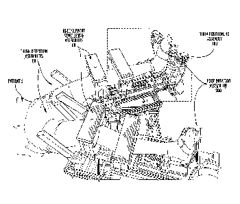
Figure 1 is a perspective view of the overall RKT apparatus 10.
Figure 2 is an illustrative side elevational view of the general components
and operation of the overall RKT apparatus 10.
Figure 3 is a closer view of a portion of that shown in Figure 2.
Figure 4 is a closer view of a portion of that shown in Figure 3.
Figure 5 is a closer view of a portion of that shown in Figure 4.
Figure 6 is a illustrative top elevational view of the general components and
operation of the overall RKT apparatus 10. The two pivoting leg support frame
assemblies are shown in generally parallel fashion.
Figure 7 is a view similar to that shown in Figure 6, except that the two
sliding support frameworks arc shown in different extension configurations.
Figure 8 is a view similar to that shown in Figure 6, except that the two
pivoting leg support frame assemblies 50 are shown in different angular
relationships.
Figure 9 is a view similar to that shown in Figure 6, except that the two
pivoting leg support frame assemblies 50 are shown in different extension
relationships.
CA 02807501 2013-02-04
WO 2012/021878
PCT/US2011/047696
Figure 10 is a view similar to that shown in Figure 6, except that the two
pivoting leg support frame assemblies 50 are shown in different extension
relationships in order to accept the legs of a user 5.
Figure 11 is a closer view of a portion of that shown in Figure 3, showing
Action D.
Figure 12 is an illustrative view showing the transverse cross section of a
thigh of a user in association with a corresponding thigh retention assembly
80.
Figure 13 is an illustrative view, showing the transverse cross section of a
knee of a user in association with a corresponding knee support/stabilizing
assembly 60 (in support mode).
Figure 14 is an illustrative view, showing the transverse cross section of a
knee of a user in association with a corresponding knee support/stabilizing
assembly 60 (in stabilizing mode).
Figure 15 is an illustrative view showing the transverse cross section of a
tibia of a user in association with a corresponding tibia retention assembly
60.
Figure 16 is a pictorial illustrative view of the pivoting interaction between
the sliding frame 122 of a tibia positioning assembly 100, a corresponding
pivoting
frame 142 of a first pivoting assembly 140 (pivots relative to sliding frame
120 via
Action F, about a vertical, "Y" axis) a corresponding pivoting frame 162 of a
corresponding second pivoting assembly 160, (pivots relative to first pivoting
assembly 140 along Action G, along a horizontal axis) and a foot plate 202,
which
(pivots relative to pivoting frame 162 along Action H).
Figure 17 shows a subjective measurement module 2000 including a
subjective measurement module dial 2001 (operated by the user) and an output
display 2002.
Figure 18 shows a subjective measurement module 2200 including a
subjective measurement module slide 2201 (operated by the user) and an output
display 2202.
Figure 19 is another pseudo-overhead view of the overall RKT apparatus
10.
Figure 20 is a view similar to Figure 19, with the Tibia Positioning
Assemblies 100 and their respective Tibia Containing Assemblies 180 "splayed"
relative to the parallel configuration of Figure 19.
11
CA 02807501 2013-02-04
WO 2012/021878
PCT/US2011/047696
Figure 21 is similar to Figure 20 but from different viewpoint and with
patient 5 in place.
Figure 22 is similar to Figure 21 but a closer view.
Figure 23 is similar to Figure 20 but without knee support stabilizing
assemblies 60.
Figure 24 is similar to Figure 23 but more approximating a side elevational
view.
Figure 25 is even more approximating a side elevational view relative to
Figure 24.
Figure 26 is a view of the main frame assembly 20 and other lower
situation elements.
Figure 27 is a slight overhead view from the foot of the device 10, shown
without knee support stabilizing assemblies 60.
Figure 28 is a slight overhead view from the foot of the device 10, showing
two motors 168 and 206, and the foot rotation assembly 200 (which includes
straps
for holding the foot).
Figure 29 is a slight overhead view from the foot of the device 10, showing
two motors 168 and 206, the foot rotation assembly 200 (which includes straps
for
holding the foot), and the pivoting frame 142.
Figure 30 is a slightly lower view than Figure 29.
Figure 31 is a slightly pulled back view than Figure 30.
Figure 32 is a view from the head of the device, without the bars 84 shown
for viewing ease.
Figure 33 is a view similar to Figure 32.
Figure 34 shows the movement axis of one of the laterally slidable knee
support pads 64.
Figure 35 is a view of an exemplary sensor cluster 1000.
Figure 36 shows a subjective measurement module 2100 including a
subjective measurement module dial 2101 and an overall machine stop button
2102.
Figure 37 is a slight overhead view of an additional embodiment of the
overall RKT apparatus 10 containing tibia containing assemblies 1180 and a
plurality of bladders 1190.
12
CA 02807501 2013-02-04
WO 2012/021878
PCT/US2011/047696
Figure 38 is a front view of the tibia containing assemblies 1180 and
bladders 1190 of Figure 37.
Figure 39 is a slight overhead view of an additional embodiment of the
overall RKT apparatus 10, together with a system 3000 according to various
embodiments for providing accurate and reliable dynamic evaluation of 'joint
play.'
DETAILED DESCRIPTION OF VARIOUS EMBODIMENTS
I. GENERAL OVERVIEW
The present inventions now will be described more fully hereinafter with
reference to the accompanying drawings, in which some, but not all embodiments
of the inventions are shown. Indeed, these inventions may be embodied in many
different forms and should not be construed as limited to the embodiments set
forth
herein; rather, these embodiments are provided so that this disclosure will
satisfy
applicable legal requirements. Like numbers refer to like elements throughout.
Generally described, various embodiments of the present invention provide
robotically controlled devices and methods for evaluating the knee, although
other
joints and limbs can likewise be evaluated such as the elbow and arm. In one
aspect of the invention, devices and methods are provided, which apply a known
torque to the lower leg of a user and monitor the reaction to this torque at
the knee.
Such devices and methods may be generally configured to control the direction,
rate, and mag-nitude of force and/or torque application in all three
directions (e.g.,
the x, y, and z axes, as described in further detail below), independently to
two legs
of a patient. In various embodiments, the user's femur and ankle are
stabilized
such that the movement of the tibia at the knee in response to a given torque
can be
accurately measured.
In various embodiments of the present invention, the torque is applied by
one or more computer controlled motors. In at least one embodiment, such is
accomplished by the use of six (6) brushless servo motors. The computer may be
programmed to instruct the motor(s) to perform any desired diagnostic routine.
Custom software may be utilized on the computer to calculate the appropriate
amount of torque to be used by each motor during testing based on the person's
13
CA 02807501 2013-02-04
WO 2012/021878
PCT/US2011/047696
height and weight. The desired torque thresholds are then communicated with
the
motors.
After the person has been properly positioned, the software may then signal
the motor(s) to perform the knee laxity testing. For example, the diagnostic
routine
may comprise rotating the user's lower leg in a clockwise direction from a
neutral
position until a predetermined threshold is reached and then back to neutral.
This
procedure may be repeated for three (3) or more cycles. Then, the user's leg
may
be rotated from a neutral position in a counterclockwise direction until a
predetermined threshold is reached and back to neutral for three cycles. In
another
example, the diagnostic routine may comprise the rotating of a user's lower
leg in a
clockwise direction until a predetermined threshold is met and then rotate in
a
clockwise direction until a predetermined threshold is met in a substantially
fluid
motion. This procedure may be repeated for several cycles. Clockwise and
counterclockwise rotations can be made in either the x, y, or z axes, by
placing the
motor in different orientations.
In various embodiments, both of the user's lower legs may be rotated
simultaneously. For example, the user's left leg may be rotated counter
clockwise
(external rotation) and then clockwise (internal rotation) while the user's
right leg
is rotated clockwise (external rotation) and then counter clockwise (internal
rotation). By rotating the legs simultaneously in opposite directions, the
movement
in the hip area can be minimized since the motions counter act each other.
This
allows evaluation of not only two limbs simultaneously, but also both joints
of
both limbs (e.g. two knees and two ankles).
While the diagnostic routine is performed, various parameters may be
monitored to evaluate the performance of the knee. In one embodiment, angle of
rotation and torque measurements are taken at regular intervals during the
diagnostic routine. In certain embodiments, the regular intervals may be 120
times
per second, collecting the torque currently being applied by each motor and
each
motor's encoder position. From this data, a hysteresis curve can be generated,
which may be used to evaluate the performance of the knee. Further, knee joint
laxity may be determined by measuring the amount of motion of the tibia
relative
to the femur as the tibia is perturbated in single and/or multiplanar motions.
More
detailed measurement techniques are described elsewhere in this application.
14
CA 02807501 2013-02-04
WO 2012/021878 PCT/US2011/047696
In other embodiments, other methods may be used instead of the motor
encoders to measure relative motion of the tibia relative femur or through the
use
of an external measurement system. External measurement systems can be any
number of instrumented systems used to calculate arthrokinematics, including
but
not limited to electromagnetic, optoelectronic, or ultrasonic motion tracking
systems, or other imaging methods such as computed tomography (CT), magnetic
resonance imaging (MRI), positron emission tomography (PET), bone scintigraphy
(bone scan), dual energy X-ray absorptiometry (DEXA), diagnostic ultrasound,
fluoroscopy, radiography, or other imaging methods.
Various embodiments of the present invention further provide an accurate
and reliable measure of joint motion in order to better diagnose and treat
orthopaedic conditions related to altered joint play. The ideal method to
dynamically evaluate joint play is the combination of the accuracy of medical
imaging, such as computed tomography (CT), magnetic resonance imaging (MRI),
positron emission tomography (PET), bone scintigraphy (bone scan), dual energy
X-ray absorptiometry (DEXA), diagnostic ultrasound, fluoroscopy, radiography,
or
other imaging methods, and the controlled torque application of a computer-
controlled motorized system. Due to the potential risks to the clinician or
technician associated with medical imaging techniques, the use of medical
imaging
thus prohibits the clinician from being able to apply the torques necessary to
evaluate the joint. A computer-controlled motorized system improves the
ability to
control torque application without any additional risk to either the patient
or
clinician.
II. ELEMENTS LIST
The invention is configured to be used by a patient/user 5. The elements of
the invention include the following:
10. Overall RKT Apparatus
20. Stationary Base Frame Assembly
30 support cushion
40. sliding support framework
42 Clamping members
50 Pivoting Leg Support Frame Assemblies (2)
60 Knee Support/Stabilizing Assembly
CA 02807501 2013-02-04
WO 2012/021878
PCT/US2011/047696
62 telescoping pedestal
64 Laterally Slidable Support pad
66 clamp assembly
68 Top plate
70 rods (4) extending from one side of plate
72 main stabilizing pad
78 rod clamp assembly
80 Thigh Retention Assembly
82 Base
84 Retention bars
86 Adjustment Assembly
87 Adjustment Assembly Handwheel
100 Tibia Positioning Assembly
120 sliding frame
140 first pivoting assembly
142 Pivoting frame
148 motor
160 second pivoting assembly
162 Pivoting frame
168 motor
180 tibia retention assembly
182 base
184 adjustment rods
185 cap
186 clamp assembly
188 Pad support plates
189 pads
200 Third Pivoting Assembly (a.k.a foot rotation assembly
200)
202 foot plate
204 rotating shaft
206 motor
16
CA 02807501 2013-02-04
WO 2012/021878 PCT/US2011/047696
III. DETAILS
Overall RKT Apparatus 10
As illustrated in at least Figures 1-2, 19, and 22, various embodiments of
the overall RKT (Robotic Knee Testing) Device 10 may include the following
features:
Stationary Base Frame Assembly 20;
Support Cushion 30;
Sliding Support Framework 40;
Two (2) Pivoting Leg Support Frame Assemblies 50;
Two (2) Knee Support/Stabilizing Assemblies 60;
Two (2) Thigh Retention Assemblies 80;
Two (2) Tibia Positioning Assemblies 100;
Two (2) Third Pivoting Assemblies 200 (a.k.a. Foot Rotation
Assemblies 200).
In use, as will be described in further detail below, a patient 5 may be
positioned within the various embodiments of the overall RKT device 10, such
that
their knees are adjacent the knee support/stabilizing assemblies 60, and their
feet
are retained within the third pivoting assemblies 200.
Each of these features and their use will now be described in further detail
herein-below.
Stationary Base Frame Assembly 20
As illustrated in at least Figures 2-4, the stationary base frame assembly 20
according to various embodiments of the overall RKT device 10 is configured to
be situated atop and supported by a supporting surface such as a floor (not
shown).
In certain embodiments, this assembly supports all of the other elements of
the
overall RKT device 10. In at least one embodiment, the stationary base frame
assembly 20 is substantially rigid and is comprised of a plurality of
substantially
rigid frame members, such as those shown in Figure 26.
Support Cushion 30
As illustrated in at least Figures 2-4, the support cushion 30 according to
various embodiments may be configured to be attached to and supported by the
stationary base frame assembly 20. In other envisioned embodiments, the
cushion
17
CA 02807501 2013-02-04
WO 2012/021878
PCT/US2011/047696
30 may be integrally formed as part of the assembly 20, as illustrated, for
example,
in Figure 19 (although not numbered). In any of these and still other
envisioned
embodiments, the support cushion 30 is generally configured to support the
posterior of a patient 5 such that the patient can lie on the patient's back,
and the
patient's legs can be situated in the overall RKT device 10, as shown for
example
in at least Figures 1, 3, 21, and 23.
S1idin2 Support Framework 40
As illustrated in at least Figures 2-4 and 26, the sliding support framework
40 according to various embodiments, may comprise a substantially rigid
substructure slidably supported atop the stationary base frame assembly 20. In
this
manner, the support framework 40 may, in these and still other envisioned
embodiments, be configured to slide relative to the stationary base frame
assembly
20 along a linear X axis. This movement is designated as "Action A" by the
arrows
in, for example, Figure 2.
In various embodiments, the "Action A" movement is configured to
facilitate adjustment of the sliding support framework 40 prior to its testing
function. In certain embodiments, this adjustment allows for the sliding
support
framework 40 to be properly positioned relative to the patient. This
adjustment is
not made to accommodate varying leg lengths, but allows for proper positioning
of
the testing apparatus even if the patient is positioned too far toward either
the head
or foot of the bed. While in the embodiment shown in Figure 2 this adjustment
is
along the X axis and is linear, alternative possible, single or multiple, axes
of
adjustment may be envisioned as within the scope of the present invention.
As will be described below in further detail, the two pivoting leg support
frame assemblies 50 according to various embodiments may be attached above and
supported by the sliding support framework 40. In this manner, in at least
certain
embodiments, the frame assemblies 50 may be likewise adjusted as the sliding
support framework 40 is adjusted, as may be desirable for particular
applications.
In use, according to various embodiments, in order to adjust the sliding
support framework 40 relative to the stationary base frame assembly 20, the
patient
5 (a.k.a. user 5) may be first positioned in place as generally shown in at
least
Figures 1 and 3. During such positioning, a releasable connection 42 according
to
18
CA 02807501 2013-02-04
WO 2012/021878
PCT/US2011/047696
various embodiments between the sliding support framework 40 and the
stationary
base frame assembly 20 is disengaged, thereby permitting adjustment of the
framework 40 relative to the assembly 20, as necessary to fine-tune the
positioning
of the patient 5. In at least one embodiment the releasable connection
comprises at
least two clamping members 42, as illustrated in in Figure 3, although in
other
envisioned embodiments, any of a variety of alternative type or number of
connections may be employed between the sliding support framework 40 and the
stationary base frame assembly 20.
Tn any of the above-discussed embodiments, once the patient is positioned
precisely as desired or needed, then the releasable connection 42 between the
sliding support framework 40 and the stationary base frame assembly 20 may be
engaged (see e.g., clamps 42 in Figure 3). In this manner, once the connection
or
clamps 42 are engaged, relative movement between the framework 40 and the
assembly 20 may be prevented, so as to maintain the patient 5 in the proper or
desired position.
Two (2) Pivoting Lea Support Frame Assemblies 50
As illustrated in at least Figures 2-4 and 26, the general function of each of
the two pivoting leg support frame assemblies 50 according to various
embodiments of the overall RKT device 10 is to provide a framework to support
a
corresponding leg of the patient/user such as 5.
In various embodiments, the two pivoting leg support frame assemblies 50
are pivotably attached above and supported by the sliding support framework
40.
In this manner, the assemblies 50 may be likewise adjusted as the sliding
support
framework 40 is adjusted, as previously described herein and as illustrated
in, for
example Figures 6, 7, and 9.
In various embodiments, each of the two pivoting leg support frame
assemblies 50 is pivotably mounted relative to the framework about an axis
lying
parallel to the Y axis (see Figure 2); thus they lie substantially along
mutually
parallel axes. In these and other embodiments, as best understood from Figure
6,
the pivoting actions of the assemblies 50 may be independent, in that one can
pivot
without the other. In still other envisioned embodiments, depending upon a
particular application, the pivoting actions of the assemblies 50 may be
interdependent, illustrated, at least in part by Figure 10. In any of these
described
19
CA 02807501 2013-02-04
WO 2012/021878
PCT/US2011/047696
and still further envisioned embodiments, the pivoting action is an adjustment
such
as that identified as "Action B" in, for example, Figure 2 and more fully
illustrated
in Figure 8. Action B adjustment allows the individual leg testing apparatuses
to
be aligned according to the patient's natural alignment. Improper alignment
would
pre-tension ligaments thus creating error in the test results. This adjustment
is
made to avoid such errors.
According to various embodiments, each pivoting leg support frame
assembly 50 is substantially similar to the other, and thus one can be
described as
an example of the other. In other envisioned embodiments (not shown), however,
__ each of the assemblies 50 may differ in one or more respects, as may be
desirable
for a particular application.
Further, as noted above, each pivoting leg support frame assembly 50 may,
according to various embodiments, comprise a substantially rigid substructure.
In
certain embodiments, each pivoting leg support frame assembly 50 itself
slidably
__ supports a corresponding one of two tibia positioning assemblies 100, as
illustrated
in, for example, Figure 3, and described in further detail below. In various
embodiments, as one pivoting leg support frame assembly 50 pivots, so does its
corresponding tibia positioning assembly 100. However, it should be
appreciated
that in still other envisioned embodiments, the respective assemblies 50 and
their
__ corresponding assemblies 100 may one or both pivot independently relative
to one
another, in any of a variety of combinations, as may be desired for a
particular
application.
According to various embodiments, the pivoting movement of the
respective assemblies 50 and their corresponding assemblies 100 is
substantially
__ about an axis parallel to the "X" direction, as illustrated in, for
example, Figure 2.
In at least one embodiment there are no clamps between 50 and 100, although
the
pivoting movement could be prevented via clamping after suitable adjustment.
In
the embodiment without clamps, each of the two pivoting leg support frame
assemblies 50 is free to pivotably relative to the sliding support framework
40.
Two (2) Knee Support/Stabilizing Assemblies 60
As illustrated in at least Figures 13 and 14, the general function according
to various embodiments of the knee support/stabilizing assemblies 60 is to
support
the knee, when in their "support mode" (see Figure 13), and to support and
CA 02807501 2013-02-04
WO 2012/021878
PCT/US2011/047696
stabilize the knees when in their "stabilizing mode" (see Figure 14). In
certain
embodiments, the knee support/stabilizing assemblies 60 are used in support
mode
for varus-valgus testing. In those
and other embodiments, the knee
support/stabilizing assemblies 60 arc used in "stabilizing mode" for both
antero-
posterior and rotational testing. In still other embodiments, the knee
assemblies 60
may be used in either support or stabilizing mode for any of a variety of
tests, as
may be desired for a particular application. Each of these modes will be
discussed
in further detail below, although it should be further appreciated that at
least
certain envisioned embodiments will include no knee support/stabilizing
assemblies 60 of any kind, as illustrated, for example, in Figures 23 and 27.
Support Mode (generally used in Varus-Valgus Testing)
As best illustrated in Figures 13 and 21, according to various embodiments,
the knee support/stabilizing assemblies 60 may be used in support mode for
varus-
valgus testing. When in "support mode', the knee support/stabilizing
assemblies 60
only support the knee region of the leg from underneath, and is free to move
side to
side. When in this mode, each of the knee support/stabilizing assemblies 60
includes the following elements, as illustrated in at least Figures 11 and 13:
Telescoping Pedestal 62
Laterally Slidable Knee Support Pad 64 (slidable in this mode)
Clamp Assembly 66
Plate 68
Rods 70 (4) extending from one side of plate
Stabilizing Pad 72
According to various embodiments, the telescoping pedestal 62 has a lower
end which is configured to be attached atop a corresponding pivoting leg
support
frame assembly 50. In certain embodiments, the telescoping pedestal 62
supports at
its top end a laterally slidable knee support pad 64, which is configured to
contact
and support a portion of the leg of a patient 5 proximate the knee as shown in
for
example Figure 3. When in this mode, according to these and other envisioned
embodiments, the pad 64 may be free to move laterally along with the
underneath
portion of the leg being supported. This is also known as Action J, as
illustrated in
at least Figure 13.
21
CA 02807501 2013-02-04
WO 2012/021878
PCT/US2011/047696
With reference to Figure 13 in view of Figure 3, according to various
embodiments, during varus-valgus testing, as the device rotates about pivot
point
shown in Action F, it will be necessary to allow the knee move laterally side
to
side in order to actually perform the test. This is facilitated by the
provision of the
laterally slidable knee support pad 64. Further according to various
embodiments,
during the varus-valgus testing, the knee itself need not be stabilized as in
the
anteroposterior and rotational tests described immediately below. However, the
proximal thigh may, in certain embodiments, be stabilized by the thigh
retention
assembly 80 while the foot may be stabilized by the foot rotation assembly
200, as
illustrated in at least Figure 3, for example.
Therefore it may be seen that the knee support/stabilizing assemblies 60
may be used according to various embodiments in support mode to allow for a
consistent degree of knee flexion during varus-valgus testing. Such benefit
arises
in at least certain embodiments due to the sliding pads 64 allowing the knees
to
slide laterally or otherwise, as previously described herein.
Stabilizing Mode (generally used in antero-posterior and rotational
testing)
According to various embodiments, as illustrated in at least Figures 14 and
25, the knee support/stabilizing assemblies 60 may likewise be used in
"stabilizing
mode" for both anteroposterior and rotational testing. In these and other
embodiments, during anteroposterior and rotational testing, a clamp assembly
66
may be added to minimize motion of the femur, as described in further detail
below.
When in "stabilizing mode" according to various embodiments, each of the
knee support/stabilizing assemblies 60 may include one or more of the
following
elements, generally depicted in Figures 11 and 14, as will be described in
further
detail below:
Telescoping Pedestal 62
Support Pad 64
Clamp Assembly 66
Top Plate 68
Rods 70 (4) extending from one side of plate
22
CA 02807501 2013-02-04
WO 2012/021878
PCT/US2011/047696
Main Stabilizing Pad 72
Rod clamp assembly 78
In certain embodiments, the knee support/stabilizing assemblies 60 may be
used in stabilizing mode to allow for a consistent degree of knee flexion, as
was
done during varus-valgus testing described above. However, when in stabilizing
mode, each of the knee support/stabilizing assemblies 60 also includes a clamp
assembly 66, as described in further detail below.
This clamp assembly 66 according to various embodiments may be
configured to cooperate with the support pad 64 so as to substantially
encircle the
leg and to substantially engage or grip it from the top, as illustrated in at
least
Figures 14 and 21 (in the latter as assembly 60 generally). When in this mode
according to certain embodiments, the pad 64 may not be adjusted laterally
relative
to the general longitudinal axis of the leg, as it is captured on its ends by
at least
the rods 70. According to these and other envisioned embodiments, the clamp
assembly 66 may include the following:
Top Plate 68
Adjustment Rods 70 (4) extending from one side of plate
Main Stabilizing Pad 72
Rod clamp assembly 78
According to various embodiments, the top plate 68 may be configured
such that the upper ends of four rods 70 may be attached to its underside. So
configured, the rods 70 in at least certain embodiments may extend
substantially
downwardly and slidably into through-holes defined by the pedestal 62 until
they
are clamped in place. In at least one embodiment, the rod clamp assembly 78 is
configured to clamp the rods relative to the pedestal 62 such that the top
plate 68 is
retained in place. When so retained according to these and still other
embodiments,
the pads 64 and 72 substantially surround and contact the patient's leg, as
illustrated in at least Figure 14. In still other envisioned embodiments, the
rods 70
themselves may also provide some degree of containment of the patient's leg.
Remaining with Figure 14, according to various embodiments, the shape of
pad 72 may be at least in part dictated by the need to stabilize the patella
within the
femoral trochlea. Such stabilization, in certain embodiments, prevents
undesirable
rotation and anteroposterior translation of the femur, while also satisfying a
need to
place an electromagnetic sensor, retro-reflective ball or array, ultrasonic
sensor, or
23
CA 02807501 2013-02-04
WO 2012/021878
PCT/US2011/047696
other motion tracking device on the patella. In certain embodiments, the pad
may
be "V-shaped," which then allows the device to adequately capture the patella
no
matter the patellar dimensions of a given patient. In these and still other
embodiments, the apex of the "V" shape may be deepened and/or widened in order
to create a channel or pocket for the motion tracking device to be placed on
the
patella, as may be desired for a particular application.
In various embodiments, adjustments may be made such that the rod clamp
assembly 78 is applied around the patient's leg, and in particular the
patient's
patella, by using a consistent known amount of force. For example, a downward
(e.g., posteriorly-directed) force of 25 pounds may be used when positioning
all
patients. In these and still other envisioned embodiments, a substantially
consistent
force should be used to allow for accurate and repeatable side-to-side
comparisons.
Indeed, inconsistent force application would allow one femur to be more easily
moveable than the other, thus potentially creating error in the bilateral
comparisons
of translation and rotation of the tibia relative to the femur between the
person's
right and left knees.
Height Adjustment of Knee Support/Stabilizing Assemblies 60
Whether or not the knee support/stabilizing assemblies 60 according to
various embodiment are configured in support or stabilizing mode, the height
the
assemblies support the leg may be variable via adjustment of the telescopic
portion
of the telescoping pedestal 62. This adjustment is illustrated as Action D in
at least
Figure 2.
According to various embodiments, Action D adjustment may be provided
either prior to testing in one embodiment or to change the degree of knee
flexion in
an effort to be consistent with previously accepted clinical evaluation
procedures,
as may be desirable or necessary for a given application.
Two (2) Thigh Retention Assemblies 80
As illustrated in at least Figure 12, the general function of each of the
thigh
retention assemblies 80 is to retain the thigh of the patient/user 5 such that
internal/external and varus/valgus rotations of the femur are limited.
24
CA 02807501 2013-02-04
WO 2012/021878
PCT/US2011/047696
According to various embodiments, each thigh retention assembly may
include two retention bars 84, which are positioned on either side of the
thigh of
the patient/user's 5 thigh 82 so as to discourage it from movement lateral to
the
longitudinal axis of the tibia. In certain embodiments, the two retention bars
84 are
configured for centered adjustment, in that they arc commonly mounted within
an
adjustment sub-apparatus that facilitates their common adjustment relative to
a
common central point. In this manner, in at least one embodiment, as one bar
is
moved a given distance in one lateral direction, the other bar moves a given
distance in the opposite lateral direction. This al lows tightening or
loosening of th e
bars about the intermediate thigh without moving the thigh to one side or the
other.
This could be considered a "self-centering" feature in at least certain of the
envisioned embodiments.
Turning now to Figure 11, each thigh retention assembly 80 according to
various embodiments may include the following:
Base 82
Two (2) Retention bars 84
Adjustment Assembly 86 (see also Figures 32 and 33)
Adjustment Assembly Handwheel 87
According to various embodiments, the base 82 of the thigh retention
assembly 80 may be rigidly attached atop a corresponding one the pivoting leg
support assemblies 50. In certain embodiments, the base 82 may support a
corresponding adjustment assembly 86, which in turn may adjustably support two
retention bars 84, as further illustrated in at least Figure 12. In operation
according
to at least one embodiment, an adjustment assembly hand wheel 87 allows an
operator (such as a clinician, not shown) to rotate the handwheel 87. Rotation
of
the hand wheel 87 in this manner, according to various embodiments, rotates a
threaded rod (or analogous mechanism, as commonly known or understood in the
art) having two threaded portions of opposite direction, each one engaging
relative
to one of the retention bars 84, such that adjustment of the spacing of the
two
retention bars 84 is facilitated such that a thigh can be suitably clamped
therebetween .
Each of the two thigh retention assemblies 80 may according to various
embodiments be attached atop a corresponding pivoting leg support frame
assembly 50, such that pivoting of the pivoting leg support frame assembly 50
CA 02807501 2013-02-04
WO 2012/021878
PCT/US2011/047696
about its vertical axis (e.g., during adjustment, as previously described
herein)
likewise facilitates pivoting of the corresponding thigh retention assembly
80.
During patient set-up, it should be understood that the two retention bars 84
may generally squeeze the thigh in order to stabilize the femur while ensuring
that
the femur is centrally located in relation to both of the retention bars.
Two (2) Tibia Positioning Assemblies 100
Returning now to Figures 2 and 3, the general function of each of the two
tibia retention assemblies 100 according to various embodiments is to position
the
tibia of the patient/user 5. In certain embodiments, each of the tibia
retention
assemblies 100 includes the following features:
sliding frame 120
first pivoting assembly 140
second pivoting assembly 160
According to various embodiments, the sliding frame 120 of the tibia
positioning assembly 100 provides the sliding connection between the tibia
positioning assembly 100 and the pivoting leg support frame assembly 50, as
there
is a sliding connection between elements 50 and 120, which is Action E. Action
E,
as illustrated in at least Figure 2 provides a degree of adjustment, which
allows the
tibia positioning assembly 100 to be adjusted according to the patient's leg
length.
First Pivoting Assembly 140
Turning now to Figure 5, the first pivoting assembly 140 according to
various embodiments may be pivotably mounted relative to the sliding frame 120
of the tibia positioning assembly 100. In this manner, in certain embodiments,
the
first pivoting assembly 140 may be configured to pivot relative to sliding
frame
120 via Action "F" (see e.g., Figure 2), about a vertical axis along the "Y"
axis.
Remaining with Figure 2, it should be understood that Action -F" action
according to various embodiments is driven and controlled by motors 148 (see
at
least Figures 30 and 31), and provides a varus-valgus torque to the knee. Such
action around the axis of rotation is used for valgus-varus or medial-lateral
testing.
One current embodiment uses a servomotor to provide the rotational force,
although other manual or mechanical methods of force application could be
used.
26
CA 02807501 2013-02-04
WO 2012/021878
PCT/US2011/047696
According to various embodiments, the first pivoting assembly 140
includes the following:
Pivoting frame 142 (See, e.g., Figure 16)
Motor 148 (see at least Figures 30 and 31)
Focusing upon at least Figure 16, it should be understood that the pivoting
frame 142 according to various embodiments provides the pivoting connection
between the first pivoting assembly 140 and the sliding frame 120 and in at
least
certain embodiments the motor 148 (see Figures 30 and 31) drives this pivoting
action. Further, in at least certain embodiments, the pivoting frame 142 may
be
configured in substantially the same manner as pivoting frame 162, as will be
described in further detail here-below. In other embodiments, the pivoting
frame
142 and frame 162 may be substantially different in shape, size and/or
configuration, as may be desired for a particular application.
Second Pivoting Assembly 160
Returning to Figure 5, the second pivoting assembly 160 according to
various embodiments may be configured to be pivotably mounted relative to the
first pivoting assembly 140, such that the second pivoting assembly 160 pivots
relative to the first pivoting assembly 140 via Action "G" (see Figure 2),
about a
horizontal axis shown by pivot point GPP (see Figure 4). In certain
embodiments,
this axis is the axis of rotation (normal to the drawing plane, in axis "Z")
for
anteroposterior laxity testing, causing the rotation indicated as Action G. At
least
one current embodiment uses a servomotor 168, as illustrated in at least
Figure 5,
so as to provide the rotational force, although other manual or mechanical
methods
of force application may be envisioned and/or used, as desirable for any of a
variety of applications.
According to various embodiments, Action G, whether manually driven or
driven and controlled by motors 168, is configured to provide internal-
external
rotation torque to the tibias, as will be described in further detail below.
In these
and still other envisioned embodiments, the second pivoting assembly 160 may
include any or all of the following features:
Pivoting frame 162
Clamp 163 (see Figure 5)
Motor 168 (see Figures 5 and 27-29 and 31)
27
CA 02807501 2013-02-04
WO 2012/021878
PCT/US2011/047696
Tibia Retention Assembly 180
The pivoting frame 162 according to various embodiments provides the
pivoting connection between the second pivoting assembly 160 and the first
pivoting assembly 140, and in at least the illustrated embodiment the motor
168
drives this pivoting action. In other embodiments, as previously described,
alternative manual or mechanical methods and/or devices may be employed. In
any of these and other envisioned embodiments, the tibia retention assembly
180,
as illustrated in at least Figures 20, 21 and 25, may be configured to be
attached at
the free end of the pivoting frame 162. According to various embodiments, the
location along the patient/user's leg that the tibia retention assembly 180
contacts
the leg may be adjustable via Action "I" as illustrated in at least Figures 2,
4, and
5, which is an adjustment of the length of the pivoting frame 162.
Turning specifically to Figure 4, Action I adjustment according to various
embodiments, may be provided so that the location of force application during
the
anteroposterior, mediolateral, or valgus/varus testing can be held consistent
for
each patient. For example, the location of force application may need to be 1"
distal to the tibial tuberosity; therefore, this portion of the frame must be
adjusted
so that the location of force application can be consistently located for
patients.
Once Action I adjustment is provided clamps such as 163, as provided according
to
various embodiments, may be clamped down so Action I movement is restricted.
In other embodiments, any of a variety of commonly known and understood
mechanisms may be used and operated so as to selectively permit and/or
restrict
Action I movement.
Tibia Retention Assembly 180
Referring now to at least Figures 5 and 15, the tibia retention assembly 180
according to various embodiments may be configured to laterally retain the
tibia
during at least the anteroposterior and varus-valgus testing processes. In at
least
certain embodiments, the tibia retention assembly 180 includes the following,
each
of which as illustrated in at least Figure 15:
Base 182
Adjustment rods 184
Cap 185
Clamp assembly 186
28
CA 02807501 2013-02-04
WO 2012/021878
PCT/US2011/047696
Pad support plates 188
Pads 189
According to various embodiments, the base 182 of the tibia retention
assembly 180 may be attached to the free end of the free end of pivoting frame
162
(which as seen in Figures 5 and 24 may comprise one or more pair of
telescoping
rails). In certain embodiments, the two rail-like free ends of the pivoting
frame 162
each define holes through which the adjustment rods 189 can slidably fit until
they
are clamped in place. The adjustment rods 189 all have one end rigidly mounted
to
the cap 185. In at least one embodiment, the clamp assembly 186 may be
configured to clamp the rods relative to the base such that the cap 185 is
retained in
place. In these and still other envisioned embodiments, the pads 189 may be
configured to substantially surround and contact the patient/user's leg. In at
least
the illustrated embodiment of Figures 15, the pads are attached to the rods
via the
pad support plates 188, although in still other envisioned embodiments, the
pads
may be attached relative to the rods via any of a variety of methods and
devices, as
commonly known and understood in the art and desirable for a given
application.
Remaining with Figure 15, adjustment of the clamp assembly 186
according to various embodiments may be made such that the location of the
anterior pad (185 attached to 189) is 1-2 cm above the anterior aspect of the
low
leg, with the entire system rotated about pivot point GPP so that the
posterior pad
(182 attached to 189) is located 1-2 cm below the posterior aspect of the low
leg.
Tightening the clamp assembly 186 fixes this position allowing for the system
to
function rigidly during anteroposterior and varus-valgus testing, and further
allows
for subtle changes in tibial anteroposterior position during rotational
testing.
Tibia Retention Assembly 1180
Referring now to at least Figures 37 and 38, an alternative tibia retention
assembly 1180 according to various embodiments may be configured substantially
the same as tibia retention assembly 180 so to laterally retain the tibia
during at
least the anteroposterior and varus-valgus testing processes. In at least
certain
embodiments, the tibia retention assembly 1180 further includes a plurality of
bladders 1190 configured for applying a force so as to retain at least a
portion of
the patient's tibia within the assembly. In at least one embodiment, the
plurality of
bladders 1190 are contained within corresponding cuffs that are positioned
relative
29
CA 02807501 2013-02-04
WO 2012/021878
PCT/US2011/047696
to the assembly 1180 such that two cuffs are adjacent opposing side portions
of the
assembly, one cuff is adjacent a top portion of the assembly, and one cuff is
adjacent a bottom portion of the assembly, as best illustrated in at least
Figure 38.
In other embodiments, any combination of bladders 1190 and cuffs may be
incorporated (e.g., merely one atop and one below the leg or merely two side
opposing ones) as may be desired for a particular application.
In use according to various embodiments, each of the bladders 1190 may be
selectively inflated so as to apply or increase a corresponding force to the
portion
of the patient's tibia positioned substantially adjacent each bladder. In
certain
embodiments, the bladders 1190 may be likewise selectively deflated so as to
remove or decrease the corresponding force, as desirable. In at least these
and
other envisioned embodiments, the bladders 1190 may all be inflated and/or
deflated simultaneously, while in still other envisioned embodiments, each of
the
bladders 1190 may be manipulated individually.
According to various embodiments, a single pressure sensor may be
connected to the bladders 1190 (e.g., via the lines or tubes, as seen (but not
numbered) in at least Figure 38)) and used to measure the change in pressure
for
the same. In certain embodiments, multiple pressure sensors may be employed,
as
may be desirable for a particular application. Still other embodiments may
employ
additional and/or alternative sensors or measurement tools, as may be desired.
Two (2) Third Pivoting Assemblies 200 (a.k.a. Foot Rotation
Assemblies 200)
Returning again to Figure 5, each third pivoting assembly 200 according to
various embodiments includes at least the following features:
foot plate 202
rotating shaft 204
motor 206
According to various embodiments, the foot plate 202 of each of the third
pivoting assembles 200 may be pivotably mounted relative to the pivoting frame
162 of the second pivoting assembly 160 via a rotating shaft 204, such that
the foot
plate 202 pivots relative to the pivoting frame 162 via Action "H," as
illustrated in
at least Figure 4.
CA 02807501 2013-02-04
WO 2012/021878
PCT/US2011/047696
Action "H" of Figure 4 is powered movement about an axis of rotation for
tibial internal and external rotation testing. At least one current embodiment
uses a
servomotor 206 to provide the rotational force, although other manual or
mechanical methods of force application could be used, as desirable for any of
a
variety of given applications, as commonly known and understood in the art. In
these and still other embodiments using the motor 206, such may be configured
with a housing mounted relative to the pivoting frame 162, such that the motor
drives the rotating shaft 204, which itself drives the foot plate 202. Of
course, it
should be understood that any of a variety of alternative configurations may
be
envisioned as within the scope of the present invention, as may be desirable
for a
given application.
Actions of the Apparatus
Reference is made to Figures 2 and 3, which show all the actions performed
by various embodiments of the overall RKT device 10. These actions are
designated primarily upon Figure 2, with capital letters in circles; for
example
Action is designated with a circle with an "A" inside.
Action A ¨ This adjustment according to various embodiments allows for
the entire testing system to be properly positioned relative to the patient.
This
adjustment is not made to accommodate varying leg lengths, but allows for
proper
positioning of the testing apparatus even if the patient is positioned too far
toward
either the head or foot of the bed. In at least the shown embodiment this
adjustment is along the X axis and is linear.
Action B ¨ This adjustment according to various embodiments allows the
individual tibia positioning assemblies to be aligned according to the
patient's
natural alignment, as may be seen in at least Figures 8 and 10, respectively.
Improper alignment can potentially pre-tension ligaments, thus creating error
in the
test results. The adjustment of Action B according to various embodiments is
made
to avoid such errors. In one embodiment, the tibia positioning assemblies are
able
to be moved by hand on sliding contact C; however, the coefficient of friction
is
such that the valgus-varus position of the tibia positioning assemblies may be
maintained during laxity testing. In another embodiment the tibia positioning
assemblies pivot freely and independently, including during testing, to allow
for
proper varus-valgus alignment of the limb to match the person's natural
alignment.
31
CA 02807501 2013-02-04
WO 2012/021878
PCT/US2011/047696
In another embodiment, the tibia positioning assemblies are clamped relative
to
their supporting frame just prior to testing.
Action C ¨ This is a frictional sliding contact point (1 of 2) which supports
the tibia positioning assemblies as they pivot according to various
embodiments.
Action D ¨ As noted above, Action D adjustment is provided prior to
testing in one embodiment to change the degree of knee flexion in an effort to
be
consistent with previously accepted clinical evaluation procedures. However,
alternate embodiments and methods include the use of automated actions to
perform more complicated, multi-planar motions. For example, the apparatus
could
be so used to simulate the pivot shift test which involves applying internal
rotation
and v-algus torques while at the same time increasing the degree of knee
flexion. As
noted, Action D according to these and still other envisioned embodiments
changes
the degree of knee flexion.
Action E ¨ This adjustment according to various embodiments allows the
tibia positioning assembly 100 to be adjusted according to the patient's leg
length.
In a second embodiment, this action can be automated with the use of a ball
screw,
worm gear, or other motorized linear actuator. The entire tibial positioning
assembly 100 may then be moved closer to or further away from the support
cushion 30. Moving the tibial positioning assembly closer to the support
cushion
would increase the degree of knee flexion and moving further away from the
support cushion 30 would then move the knee into extension. This allows, in at
least certain embodiments, for individualized static positioning of the knee
for each
person or would allow for the degree of knee flexion or extension to be
changed
during laxity testing, and could be coordinated to perform multiplanar testing
with
any or all of the three testing axes (Actions F, G, and H).
Action F ¨ This action according to various embodiments is driven and
controlled by motors 148, and provides a varus-valgus torque to the knee. Such
action around the axis of rotation is used for valgus-varus or medial-lateral
testing.
At least one envisioned embodiment uses a servomotor to provide the rotational
force, although other manual or mechanical methods of force application could
be
used.
Action G, about Pivot Point GPP ¨ According to various embodiments,
GPP is the axis of rotation (normal to the drawing plane, in axis "Z") for
anteroposterior laxity testing, causing the rotation indicated as Action G. At
least
32
CA 02807501 2013-02-04
WO 2012/021878
PCT/US2011/047696
one envisioned embodiment uses a servomotor 168 to provide the rotational
force,
although other manual or mechanical methods of force application could be
used.
Action H ¨ This is the axis of rotation for tibial internal and external
rotation testing according to various embodiments. At least one envisioned
embodiment uses a servomotor 206 to provide the rotational force, although
other
manual or mechanical methods of force application could be used.
Action I ¨ This action may be adjusted according to various embodiments
so that the location of force application during the anteroposterior,
mediolateral, or
valgus/varus testing can be held consistent for each patient. For example, the
location of force application may need to be 1" distal to the tibial
tuberosity;
therefore, this portion of the frame must be adjusted so that the location of
force
application can be consistently located for patients.
Action J ¨ This action according to various embodiments is lateral sliding
movement of laterally slidable knee support pad 64 knee support/stabilizing
assembly 60. The laterally slidable knee support pad is slidably mounted
relative to
the pedestal 62 of the knee support/stabilizing assembly 60, such that it can
move
about an axis such as shown by the arrows in Figures 15 and 34.
Input/Output Si2na1s of the Device
As may be seen from Figures 27-31, various embodiments of the testing
procedures made possible by the overall RKT device 10 may be accomplished by
the use of six (6) brushless servo motors, namely two motors 148, two motors
168,
and two motors 208. It should be understood that fewer or additional motors
may
be employed, as may be desirable for any of a variety of envisioned
applications,
in particular those involving one or more manual inputs, as previously
described
herein.
In certain embodiments, perhaps best illustrated in Figure 31, all input and
output signals are accomplished through the use of these motors. However, it
should be noted that other motion tracking systems may be used in conjunction
with the motors in order to accurately and reliably measure motion of the
tibia
relative to the femur. Examples of motion tracking systems would include, but
not
limited to, optoelectronic, electromagnetic, ultrasonic, fluoroscopic, stereo
bi-plane
radiographic, and other imaging methods commonly used to measure motion of the
tibia relative to the femur in vivo.
33
CA 02807501 2013-02-04
WO 2012/021878
PCT/US2011/047696
According to various embodiments, input signals are sent to the motors
regarding the target torque thresholds for each of the three tests for each
patient, as
well as the signals to start and complete each test. In a similar fashion
according to
various embodiments, output signals arc sent from or regarding the motors
regarding the amount and direction of torque from each motor as well as the
encoder count for each motor.
The Testin2 Processes
As may be understood at least initially from Figure 1, the patient 5 may be
positioned supine, and motion tracking sensors are applied to each tibia,
femur, and
the patella as needed. The patient's feet are then strapped into the
corresponding
Foot Rotation Assemblies 200.
The underlying rationale of the laxity testing methods described in the
following paragraphs is that the tibia, which is an intercalary bone, is
perturbated
in a given direction by the device, and the motion of the tibia relative to
the femur
is measured. This is inherently different from all other techniques and
devices and
methods previously utilized to evaluate knee joint laxity. Simply put, the
tibia
retention assembly does not squeeze tightly on the lower leg, but leaves gaps
between the assembly and the anterior, posterior, medial, and lateral aspects
of the
proximal low leg. Squeezing tightly on the proximal low leg makes it more
difficult to accurately measure motion of the tibia itself, as the act of
squeezing the
proximal low leg causes compression of soft tissues thus resulting in greater
soft
tissue artifact or error in the measurements of tibial motion. Squeezing makes
it
more difficult to differentiate motion of the tibia from motion of the skin,
muscle,
adipose, etc. On the contrary, by perturbing the tibia in a given direction,
only one
aspect of the low leg is compressed, thus allowing accurate measurements of
tibial
motion relative to the femur. It is for this reason that this system has
demonstrated
excellent reliability (ICC>0.87) with accuracies of= 0.3 mm and + 0.5 .
Once the patient is properly positioned in the RKT apparatus 10, the RKT
apparatus 10 simultaneously cycles both knees into 1) internal and external
rotation, 2) anterior and posterior translation, and 3) varus and valgus
rotations.
Each test can be performed individually or performed in any combination or
order
of the three motions.
34
CA 02807501 2013-02-04
WO 2012/021878
PCT/US2011/047696
Each of these three motions may be tested separately. For each motion,
three cycles of each motion are performed to precondition the structures of
the
knee, and both the amount of torque applied and the rate at which the torque
was
applied arc controlled by the system. Following the three preconditioning
cycles,
three test cycles arc performed with the magnitude, direction, and rate of
force/torque application as well as motion of the tibia relative to the femur
being
collected. Each of the three motions will now be discussed individually.
Internal and External Rotation
First, according to various embodiments, the patient is suitably positioned
within the RKT apparatus 10, and patient's feet are ensured to be suitably
strapped
into the corresponding Foot Rotation Assemblies 200. Each of the knee
support/stabilizing assemblies are configured in stabilizing mode (clamp
assembly
66 in place, see, for example Figure 21) and adjusted such that the knee is
suitably
stabilized. As each of the two pivoting leg support frame assemblies 50 is
free to
pivot relative to the sliding support framework 40, the legs of the patient,
the two
pivoting leg support frame assemblies 50 thus tend to be aligned according to
the
patient's natural alignment. Improper alignment would pre-tension ligaments
thus
creating error in the test results. All adjustments are then complete and the
patient
is then ready to be tested.
According to various embodiments, the knee is preconditioned by
performing at least three complete rotational cycles. Following the 3
preconditioning cycles, 3 additional test cycles will be performed and the
data from
these test cycles will be used for analysis. Of course, it should be
understood that
in other envisioned embodiments, any of a variety of cycles or testing
programs
may be employed, as desirable for a particular application.
After such preconditioning, the RKT apparatus 10 then provides torque first
in tibial external rotation at a velocity of 5 /sec until the desired torque
threshold of
6 N-m is reached. The RKT apparatus 10 then reverses direction until the
threshold
is reached in internal rotation, thus completing one cycle. The RKT again
reverses
direction and repeats this process for two additional cycles. The number of
cycles
performed can be increased or decreased as necessary and the torque threshold
and
test velocity can also be individually adjusted if deemed appropriate. Testing
for
internal and external rotation is thus complete.
CA 02807501 2013-02-04
WO 2012/021878
PCT/US2011/047696
Anterior and Posterior Translation
First, the patient is suitably positioned within the RKT apparatus 10, and
patient's feet are ensured to be suitably strapped into the corresponding Foot
Rotation Assemblies 200. Each of the knee support/stabilizing assemblies arc
configured in stabilizing mode (clamp assembly 66 in place) and adjusted such
that
the knee is suitably stabilized. As each of the two pivoting leg support frame
assemblies 50 is free to pivotably relative to the sliding support framework
40, the
legs of the patient, the two pivoting leg support frame assemblies 50 thus
tend to
be aligned according to the patient's natural alignment. Improper alignment
would
pre-tension ligaments thus creating error in the test results. The pivoting
frame 162
is adjusted to control the location of force application so that force is
applied with
the tibia containing assembly 180 in a location that proximal to the
gastrocnemius
muscle belly and distal to the tibial tuberosity. The position is then
maintained by
tightening clamp 163. The tibia containing assembly 180 is then adjusted so
that
the pads 189 are located 1 cm away from both the anterior aspect of the tibia
and
the posterior aspect of the gastrocnemius. This adjustment is made using
adjustment rods 184 and the position is maintained by tightening clamp 186.
According to certain embodiments, all adjustments are then complete and the
patient is then ready to be tested. In other embodiments having an alternative
tibia
containing assembly 1180 having a plurality of bladders 1190 contained within
cuffs (e.g., pads substantially similar to pads 189) further adjustment of the
bladders (e.g., by inflation and/or deflation thereof) may be completed prior
to
performing patient testing.
The knee is preconditioned by performing 3 complete rotational cycles.
Following the 3 preconditioning cycles, 3 additional test cycles will be
performed
and the data from these test cycles will be used for analysis.
During both preconditioning and test cycles, the RKT apparatus 10
provides torque first in anterior translation at a velocity of 1 mm/s (The 1
mm/s
was based on the velocity at the knee joint of an average male using accepted
anthropometric normative values.) until the desired force threshold is
reached. The
RKT apparatus 10 then reverses direction until the threshold of 223 N is
reached in
posterior translation, thus completing one cycle. In anterior translation, the
applied
force takes into account the patient's height and weight, equaling 134 N in
addition
the force necessary to raise the mass of the low leg. The weight of the low
leg can
36
CA 02807501 2013-02-04
WO 2012/021878
PCT/US2011/047696
be estimated based on the patient's height and weight based on accepted
anthropometric measures. For example, the force necessary to raise a low leg
that
weighs 20 lb is 89 N. The force threshold is then 134 N plus 89 N, for a total
of
223 N.
The RKT again reverses direction and repeats this process for two
additional cycles. The number of cycles performed can be increased or
decreased
as necessary and the force threshold and test velocity can also be
individually
adjusted if deemed appropriate. Testing for anterior and posterior translation
is
thus complete.
Varus and Valgus Rotation
The knee is preconditioned by performing 3 complete varus-valgus cycles.
Following the 3 preconditioning cycles, 3 additional test cycles will be
performed
and the data from these test cycles will be used for analysis.
After such preconditioning, the RKT apparatus 10 then provides torque first
in varus rotation at a velocity of 1 /sec until the desired torque threshold
is
reached. Under one method, the torque threshold is calculated based on the
patient's height and weight, and is equal to 1 N-m per unit of Body Mass Index
(kg/m2). Alternately, the torque threshold could be based on the patient's
height
and weight and/or BMI, or a fixed torque threshold of 7 or 12 N-m could be
used
as has been done in previous studies.
Since there is a frictional component of the slide attached to the knee
pedestal and since the force is being applied at varying lever lengths based
on
patient height, we are increasing/decreasing the force based on patient height
and
weight in order to apply enough force to move the joint in this plane. The RKT
apparatus 10 then reverses direction until the threshold is reached in valgus
rotation, thus completing one cycle. The RKT again reverses direction and
repeats
this process for two additional cycles. The number of cycles performed can be
increased or decreased as necessary and the torque threshold and test velocity
can
also be individually adjusted if deemed appropriate. Testing for varus-valgus
rotation is thus complete.
Testing for varus and valgus rotation according to various embodiments is
thus complete.
37
CA 02807501 2013-02-04
WO 2012/021878
PCT/US2011/047696
Sensin2 Devices and Methods of Use
As shown in at least Figure 35, a Sensor Cluster 1000 is shown. This sensor
cluster in various embodiments anticipates the use of electromagnetic motion
tracking system consisting of an electromagnetic transmitter and 4 to 6 (or
any of a
variety number of) electromagnetic sensors. The electromagnetic system outputs
the location and orientation of each sensor, and a custom software is used to
calculate the six degree of freedom kinematics of the knee during laxity
testing.
The tracking system and custom software allow for accurate and clinically
meaningful measurements of motion of the tibia relative to the femur. In
further
embodiments, the motion tracking system is a Polaris Spectra system
manufactured by Northern Digital Inc., of Waterloo, Canada. The Polaris
System uses a camera to measure three-dimensional positions and orientations
of
retro-reflective markers placed on a patient. The reflective markers are
affixed to
rigid arrays that are then applied to the patient's thigh, low leg, and foot.
The
Polaris system is able to determine the position and orientation of each of
the
rigid arrays in space, and therefore the relative position and orientation of
the
patient's knee. It is able to measure joint motion in six degrees of freedom,
meaning that it can determine both rotation and translation of the joint about
all
three planes of motion. In additional embodiments, opto-electronic tracking
devices may be used, which emit optical signals that are received by a camera
and
the camera is configured to follow the three-dimensional position of each
sensor,
thus allowing for the determination of the three-dimensional position and
orientation with respect to one another of the various bones.
In further embodiments, ultrasonic devices may be used. These devices
determine their three-dimensional position and orientation with respect to one
another.
In addition to conventional motion tracking systems that feature skin-based
sensors or markers, this system could be used in conjunction with medical
imaging
systems to evaluate relative motion between the tibia and femur. The materials
of
the device could be made from non-ferrous materials to allow use with medical
imaging systems, which may include, but are not limited to, computed
tomography
(CT), magnetic resonance imaging (MRI), positron emission tomography (PET),
bone scintigraphy (bone scan), dual energy X-ray absorptiometry (DEXA),
diagnostic ultrasound, fluoroscopy, radiography, or other imaging methods.
38
CA 02807501 2013-02-04
WO 2012/021878
PCT/US2011/047696
In addition to using external devices to measure the relative motion
between the tibia and the femur, external measurement devices can be
incorporated
within the system as a direct measure of the force or torque being applied to
the
joint. In one embodiment, the assembly that perturbates the tibia into
anteroposterior translation and varus-valgus rotation can be made with a
plurality
of inflatable air cuffs. These air cuffs may be individually attached to
pressure
sensors so that as force is applied to the leg, the change in pressure is
recorded and
used for later analysis. The air cuffs may also be attached in series since
only one
cuff is being compressed at a time in order to reduce the number of pressure
sensors needed to capture this information.
During the internal/external rotation portion of the diagnostic routine, an
external reaction torque transducer may be incorporated between the foot plate
and
the output shaft from the motor or gearhead. These trandueers will then record
the
torque being applied in regular intervals throughout, and then be used for
later
analysis.
Special Comment Reaardin2 Perturbation of Intermediate Joint
Note that one feature of the present apparatus and method applies to a
'perturbation' type of evaluation across every joint. For instance, the pelvis
could
be held in a clamp or device and the torso rotated at the thorax by a brace.
All of
the intercalary segments between the thorax and the pelvis would then be
subjected
to a rotational force. A CT scan could then follow accurately measuring
/recording
the motion that occurs between each of the segments. A known force is then
correlated with a known motion and a load-deformation curve is constructed
describing the relationship between these intercalary bones. The same could be
of
the elbow, wrist, shoulder, ankle, and hip. Fingers could also be evaluated.
The
'perturbation' technique is safe and opens up an entirely new way of testing.
Uses of the above Devices with Subjective Measurement Modules, such
as 2000, 2100, or 2200
Reference is now made to subjective measurement modules 2000, 2100,
and 2200 shown in Figure 17, Figure 36, and Figure 18, respectively.
39
CA 02807501 2013-02-04
WO 2012/021878
PCT/US2011/047696
Figure 17 shows a subjective measurement module 2000 including a
subjective measurement module dial 2001 (operated by the user) and an output
display 2002.
Figure 36 shows a subjective measurement module 2100 including a
subjective measurement module dial 2101 and an overall machine stop button
2102.
Figure 18 shows a subjective measurement module 2200 including a
subjective measurement module slide 2201 (operated by the user) and an output
display 2202.
The device described consists of a digital potentiometer or similar device
that a patient can continuously adjust to rate their current level of pain
(either a 0-
10 scale or "no pain" to "maximum pain" scale) during joint laxity testing. To
our
knowledge, no other joint laxity measurement system has the ability to capture
subjective pain ratings from the patient that can then correlated with the
instantaneous torque, position, and angle data being captured as part of the
joint
laxity examination. The ability to incorporate subjective pain ratings with
the
objective measures being collected with the laxity test system allows surgeons
and
other medical professionals to better understand the anatomic structure(s)
that may
be involved.
The proposed device may according to various embodiments comprise a
separate hand-held pendant to be used by a patient during instrumented joint
laxity
testing. In certain embodiments, the device may have either a dial (see
modules
2000 and 2100) or slide potentiometer (see module 2200) that a patient would
adjust according to his/her pain level at any given moment. In other
embodiments,
the patient would be able to rate his/her pain with a single hand through the
use of
a hand-held device featuring either a plunger that could be depressed with the
thumb and/or a lever or other "trigger" that could be depressed with the
fingers.
The patient could then use either depress the thumb plunger or squeeze the
trigger
to report increasing levels of pain and/or discomfort. Examples of hand held
systems that could be used include, but are not limited to, the Aurora AFX
Adjustable Control or the Omron A4EG. The Aurora device features a trigger
mechanism that could be squeezed to indicate the patient's current level of
pain
and the Omron device features a compressible area that can be squeezed by the
fingers as well as an emergency stop button that can be activated with the
thumb.
CA 02807501 2013-02-04
WO 2012/021878
PCT/US2011/047696
According to various embodiments, the subjective ratings of pain would be
output not only to the output displays shown, but also to a dedicated computer
that
would also be collecting torque and position data from the motors as well as
the
position and angle data from the three-dimensional motion tracking system. The
pain ratings would be captured at regular sub-second intervals and
synchronized
with the torque, position, and angle data. Data could be sent from the
Subjective
Measurement Module to the computer by a number of means including, but not
limited to direct USB cable or other cables, or wirelessly with a Bluetooth
connection or other wireless means.
The patient's pain rating may be output to a visual display on the pendant
in real time. Pain ratings could either be displayed using a numeric display
or
graphical display. The numeric display (see e.g., Figure 17) could range from
0.0
to 10.0, with 0 representing "No Pain" and 10 representing "Max Pain". The
graphical display (see e.g., Figure 18) may use a scrolling horizontally-
directed
line to indicate pain (y-axis) as a function of time (x-axis).
The pain measurement device may according to various embodiments also
be used as an additional safety measure for the laxity system, such that when
the
patient indicates maximum pain or pain above a pre-determined threshold (8 out
of
10 for example), then the motors applying the torque would either reverse
direction
or be disengaged. This threshold could vary in intensity for different tests
or
patient profiles, as some patients will perceive pain differently from others.
In
embodiments that feature multiple methods for patient input, one input could
be
used to rate pain and the other input be used as an emergency stop for the
knee
testing system. For example, the subjective measurement module 2100 (see e.g.,
Figure 36) features two such patient inputs. One input in certain embodiments,
the
subjective measurement module dial 2101, would be used by the pain to indicate
his or her level of pain. The second input, stop button 2102, would then be
used as
an emergency stop switch that would disengage the motors and terminate a given
laxity test. In the embodiment with thumb plunger and finger "trigger" patient
inputs, the "trigger" could be squeezed by the patient to indicate his or her
current
level of pain, and the thumb plunger could be used as an emergency stop button
that would disengage the motors and terminate a given laxity test.
In addition to pain ratings, the Subjective Measurement Module may
according to various embodiments also be used by patients to rate other
subjective
41
measures. For example, the same 0 to 10 rating system could be used for
patients
to rate their sensations of instability or the feeling of "giving way", which
is
clinically associated with joint laxity or instability.
It should also be understood that the subjective measurement module
described above could be used with other devices such as those described in
USPATNOS 6,669,660, 6,872,186, and 7,547,289, each of which may be referred
to for further details, as well as any other devices which provide range of
motion
or other similar flexion analysis and/or therapy.
Uses of the above Devices with Medical Imaging Devices within System
3000
Overall System 3000
Reference is first made to Figure 39, which shows certain elements of a
system 3000 according to various embodiments for providing accurate and
reliable
dynamic evaluation of joint play. According to various embodiments, the system
is composed of a stabilizing assembly 3010 placed proximal to the joint being
evaluated, a distal assembly 3020 that allows for dynamic manipulation of an
intermediate joint through the use of computer-controlled motorized torque
application, device or devices to allow for the measurement of the magnitude
ancUor rate of torque application, and a medical imaging system 3030 placed
intermediate to the proximal stabilizing assembly and distal assembly to allow
for
accurate measurement of joint play or motion, including, but not limited to
internal
and external rotation, flexion and extension rotation, and varus and valgus
rotation.
The methods and devices may be used to test an individual joint, but may
also be used for simultaneous bilateral joint evaluation. The present
inventions
now will be described more fully hereinafter with reference to the
accompanying
drawings, in which some, but not all embodiments of the inventions are shown.
Indeed, these inventions may be embodied in many different forms and should
not
be construed as limited to the embodiments set forth herein; rather, these
embodiments are provided so that this disclosure will satisfy applicable legal
requirements.
42
CA 2807501 2017-10-06
CA 02807501 2013-02-04
WO 2012/021878
PCT/US2011/047696
Proximal Stabilizing Assembly 3010
According to various embodiments, the proximal stabilizing assembly 3010
comprises an apparatus that is generally configured to grasp the leg(s) of the
patient approximately above each knee(s), as shown in at least Figure 39. It
should
be understood that while the assembly 3010, as illustrated, is configured to
grasp
the patient/user's leg(s), such may be alternatively configured to grasp any
of a
variety of limb and/or joint portions (e.g., the non-limiting examples of
wrist,
forearm, upper arm, elbow, shoulder, thorax, etc.), as may be desirable for a
particular application.
The function of the stabilizing assembly 3010 according to various
embodiments is to substantially limit or direct motion of the proximal segment
while the intermediate joint of the body is manipulated. In certain
embodiments,
the assembly 3010 may be free-standing, but may in other embodiments also be
fixed to the moveable gantry of medical imaging devices. In at least the
embodiment depicted in Figure 39, the assembly 3010 is customized to be
slotably
inserted into the gantry of a computed tomography (CT) scanner for the use of
evaluating the human patellofemoral joint. In at least that embodiment and
other
envisioned embodiments, the proximal stabilizing assembly may be slotably
inserted into the gantry of a CT scanner, and may be rigidly locked into place
relative to the gantry. In these and still other envisioned embodiments,
the
assembly 3010 may feature several inferior adjustable components that allow
for
the patient's limb to be stabilized in its natural resting alignment.
According to various embodiments, by using the inferior adjustment
components according to various embodiments, the left and right stabilizing
subassemblies can be moved either medially or laterally to be appropriately
positioned to the desired degree of hip abduction. In certain embodiments, the
upper left and right stabilizing subassemblies can then be individually
pivoted to
be perpendicular to the long axis of each femur and locked into place. This
allows
the stabilizing pads to be placed parallel to the long axis of the femur thus
avoiding
uneven application of stabilizing force. In certain embodiments, the upper
left and
right stabilizing subassemblies can then be individually adjusted so that an
appropriate stabilizing force can be applied to one or both limbs. In these
and still
other envisioned embodiments, such adjustments allow the individual left and
right
stabilizing subassemblies to be aligned according to the patient's natural
alignment.
43
CA 02807501 2013-02-04
WO 2012/021878
PCT/US2011/047696
Improper alignment would pre-tension ligaments thus creating error in the test
results. This adjustment is made to avoid such errors.
The function of the proximal stabilizing assembly 3010 according to
various embodiments as described is to direct or limit the amount of long axis
rotation or mediolateral translation or rotation of the segment located
proximal to
the joint to be evaluated. It is important to note that an additional strap or
rigid
fixture may be used in conjunction with the proximal stabilizing assembly in
order
to direct or limit the amount of anteroposterior or cranial-caudal
translation. In
these and still other envisioned embodiments, the proximal stabilizing
assembly
and all subcomponents can be made from non-ferrous materials such in order to
limit any potential metal artifacts on the created images and/or to prevent
damage
to the imaging systems themselves.
Distal Assembly to Allow Controlled Joint Manipulation
According to various embodiments, the distal assembly 3020 comprises an
apparatus that is grasping the feet of the patient, as depicted in at least
Figure 39.
In various embodiments, the functions of the distal assembly 3020 are to allow
for
1) appropriate alignment of the segment distal to the joint being evaluated
prior to
the controlled manipulation of the joint and 2) the controlled manipulation of
the
joint. In this manner, much like the proximal stabilizing assembly, the distal
assembly according to various embodiments does not provide direct support of
the
joint that is to be manipulation. This then allows to joint to move freely
without
being inappropriately guided or directed if there was a direct articulation
between
the testing system and the joint itself It should be understood that while the
distal
assembly 3020, as illustrated, is configured to grasp the patient/user's feet,
such
may be alternatively configured to grasp any of a variety of limb and/or joint
portions (e.g., the non-limiting examples of wrist, ankle, pelvis, elbow,
shoulder,
etc.), as may be desirable for a particular application.
The distal assembly 3020 according to various embodiments has several
adjustments that can be made to properly position the limb for testing. In
certain
embodiments, the entire assembly can be slidably moved along a track near the
floor that is in-line with the long axis of the body to position the system
for testing
and for repositioning the system to a position at which it will not interfere
with the
conventional use of the imaging system when not in use. When positioned in at
44
CA 02807501 2013-02-04
WO 2012/021878
PCT/US2011/047696
least these embodiments for use in the evaluation, the assembly 3020 may be
locked or clamped into a fixed position to prevent motion of the entire
apparatus
during testing if desired. In this way the system can be used to maintain a
fixed
position on the floor during testing, or can be allowed to move along the
track near
the floor if it is so desired during testing. However, it should be understood
that in
still other envisioned embodiments the assembly 3020 may or may not be locked
or clamped into a fixed position, as may be desirable for a particular
application.
These and related concepts will be discussed in more detail in the following
section
related to the method of capturing and analyzing the images.
According to various embodiments, once the assembly 3020 is positioned
along the track near the floor for testing, several other adjustments may be
made to
accommodate a patient's leg length and natural alignment as well as the
desired
joint angles necessary for joint evaluation. In certain embodiments, the left
and
right aspects of the main assembly can be moved along a track that is
perpendicular to the long axis of the body to accommodate varying degrees of
knee
varus or valgus alignment and can be locked into place. In at least one
embodiment, the left and right aspects of the main assembly can be
individually
aligned, or in the case of bilateral evaluation, can be fixed to one another
with a
rigid cross-member in order to allow both assemblies to be positioned at the
same
degree of knee varus/valgus alignment. However, it should be understood that
in
still other envisioned embodiments, the left and right aspects of the main
assembly
may be otherwise configured, as may be desired for a particular application.
Similarly, according to various embodiments, a clamp may be is located on
the vertical rod for both the left and right aspects of the main assembly. The
entire
manipulation assembly (the motor/footplate combination that is used to
actually
manipulate the joint) can then be moved superiorly or inferiorly in order to
change
the relative degree of knee flexion or extension. The left and right
manipulation
assemblies can be individually aligned, or in the case of bilateral
evaluation, can be
fixed to one another with a rigid cross-member in order to allow both
assemblies to
be positioned at the same degree of knee extension. The clamping mechanism
also
allows for the long axis of the manipulation assembly to be pivoted medially
or
laterally in order to align the axis of rotation with the long axis of the
body
segment distal to the joint being manipulated. The inability to make the
adjustment
would create a situation in which the torque being applied would not be in-
line
CA 02807501 2013-02-04
WO 2012/021878
PCT/US2011/047696
with the physiologic motion of the joint, resulting in measurement errors. The
clamping mechanism can then be tightened to maintain proper alignment
throughout the test.
A second clamping mechanism according to various embodiments may be
located on the vertical rod for both the left and right aspects of the main
assembly
allows for the system to be adjusted for the patient's individual limb length.
When
loosened, the clamp allows for the elongate member attached to the
manipulation
assembly to be translated cranially or caudally in order to position the foot
on the
manipulation assembly. In addition, when loosened, the clamp allows for the
manipulation assembly to be pivoted up or down to align the axis of rotation
with
the long axis of the body segment distal to the joint being manipulated. The
inability to make the adjustment would create a situation in which the torque
being
applied would not be in-line with the physiologic motion of the joint,
resulting in
measurement errors. The clamping mechanism can then be tightened to maintain
proper alignment throughout the test.
It should be noted that one or more axis of rotation can be evaluated using
this system. Motors mounted perpendicular to the long axis of the distal
segment
on the manipulation assembly will allow for the evaluation of
flexion/extension
rotation and/or varus/valgus rotation.
Measurement of the Magnitude and/or Rate of Torque Application
The remainder of the manipulation assembly is similar in form and function
to our apparatus previously described in U.S. Patent Application 2009/0124936.
The computer-controlled motorized system allows for the consistent application
of
torque, and also features measurement devices that allow the magnitude of the
torque and rate of torque application to be measured at routine intervals
throughout
the dynamic test.
Method of using computer-controlled motorized manipulation system with
nzedical imaging systems
Once the user has been secured by the proximal stabilizing and distal
assemblies, data related to the motion of the joint can be gathered by use of
the
medical imaging system 3030 (such as the CT scanner with the central pass-
through hole in the middle shown in Figure 39, shown in a approximated
position
46
CA 02807501 2013-02-04
WO 2012/021878
PCT/US2011/047696
needed to evaluate the knee region(s). In certain embodiments, positioning of
the
user is such that he or she is positioned supine with both knees resting in 20
degrees of flexion. However, alternative positioning may be envisioned for
either
the knee or any of a variety of other joints (e.g., pelvis, shoulder, elbow,
wrist,
fingers, ankle, thorax, etc.), as desirable or necessary for a particular
application.
In various embodiments, a computer or other programmable controller is
configured to control the motors to perform a desired diagnostic routine. For
example, the diagnostic routine may comprise repeating several cycles of
rotating
the user's manipulation assemblies in a first direction (e.g., clockwise) from
a
neutral position (i.e. the foot pointing substantially upward) until a
predetermined
threshold is reached. Next, the user's leg may be rotated in a second
direction (e.g.,
counterclockwise) from the neutral position until a predetermined threshold is
reached for three cycles.
In other embodiments, the diagnostic routine may comprise the rotating of
a user's lower leg in a clockwise direction until a predetermined threshold is
met
and then rotate the in a clockwise direction until a predetermined threshold
is met
in a substantially fluid motion. This procedure may be repeated for several
cycles.
In various embodiments, both of the user's lower legs may be rotated
simultaneously. For example, the user's left leg may be rotated counter
clockwise
(external rotation) and then clockwise (internal rotation) while the user's
right leg
is rotated clockwise (external rotation) and then counter-clockwise (internal
rotation). By rotating the legs simultaneously in opposite directions, the
movement
in the hip area can be minimized since the motions counter act each other. In
other
embodiments, the rotation of each leg may be performed independently. In at
least
one embodiment, the legs may be rotated at a velocity of approximately 1.25
degrees per section, with an applied torque threshold of 6Nm. However, it
should
be understood that still other envisioned embodiments may rotate the legs at
any of
a variety of velocities, subject to any of a variety of applied torques, as
may be
desirable for a particular application.
While the diagnostic routine is performed, various parameters may be
monitored to evaluate the performance of the knee. In one embodiment, torque
measurements are taken at regular intervals during the dynamic diagnostic
routine.
At the same time, images are generated of the joint using the medical imaging
system 3000.
47
CA 02807501 2013-02-04
WO 2012/021878
PCT/US2011/047696
During the diagnostic routine, the CT scanner will be creating images at a
high frequency, such as of 1.25 hz. A 20-mm capture volume will be imaged
every
0.8 seconds throughout the dynamic test. The series of images are then used to
generate three-dimensional models of the bones, thus allowing for accurate and
reliable measurement of bony kinematics in six degrees of freedom (translation
and
rotation about three axes). For example, motion of the patella can be measured
relative to the femur in order to better understand the condition surrounding
ligamentous structures as well as the influence of bony morphology on the
motion
of the patella relative to the femur. In another embodiment, helical or spiral
imaging techniques can be utilized to create images of a larger capture
volume. In
the example of the patellofemoral joint, the gantry can be programmed to move
cranially and/or caudally throughout the course of the dynamic diagnostic
routine
in order to create images of the entire patella and not just a 20 ¨mm capture
volume. In this embodiment, the entire distal assembly can be allowed to slide
cranially and/or caudally by the body in response to the movement of the
gantry, or
may be rigidly fixed to the gantry itself to allow the gantry to directly move
the
distal assembly.
The two time series of torque information and kinematic information can
then aligned. From this data, a hysteresis curve can be generated, which may
be
used to evaluate the performance of the patellofemoral joint. In another
embodiment, an additional non-invasive fixture can be strapped or attached to
the
tibia. In this embodiment, the tibial fixture features an elongate appendage
that
projects from the tibial fixture to the imaging device's capture volume, thus
allowing for the relative motion of the tibia to be quantified. In this way,
the
patellofemoral kinematics can be evaluated while simultaneously generating
information about how the tibia moves relative to the femur, and how the
patella
moves relative to the tibia.
Embodiments Related to Other Body Segments
While the above has been generally described with regard to a
patient/user's 1 eg/knee/thi gh , it should be understood that system 3000 may
be
alternatively configured to grasp and/or perturb any of a variety of limb
and/or
joint portions (e.g., the non-limiting examples of wrist, forearm, upper arm,
elbow,
shoulder, thorax, etc.), as may be desirable for a particular application.
48
CA 02807501 2013-02-04
WO 2012/021878
PCT/US2011/047696
As a non-limiting example, it should be noted that similar methods and
devices have been developed to evaluate joint play of other joints. The elbow
can
be evaluated in much the same way as a knee, with the opportunity to utilize
one or
more axes of motorized rotation distal to the hand, with the upper arm(s)
being
supported using a proximal stabilizing assembly. This will allow for
varus/valgus,
flexion/extension, or pronation/supination laxity of the elbow to be
evaluation,
which are all vital to understanding the condition of the elbow following
ligamentous injury, radial head fractures, and any number of other orthopaedic
injuries to the joint.
In much the same way, the ankle, hip, wrist and shoulder can be
dynamically evaluated by stabilizing the proximal segment and using a distal
assembly with computer-controlled motor(s) to manipulate the joint while
measuring information about the applied torque as well as joint motion through
the
use of medical imaging techniques. Furthermore, the distal assembly can be
easily
modified to allow for dynamic evaluation of the lumbar, thoracic, or cervical
spine.
IV. CONCLUSION
The foregoing description of the various embodiments of the present
invention has been presented for purposes of illustration and description. It
is not
intended to be exhaustive or to limit the invention to the precise form
disclosed.
Obvious modifications or variations are possible in light of the above
teachings.
The embodiments were chosen and described to provide the best illustration of
the
principles of the invention and its practical application to thereby enable
one of
ordinary skill in the art to utilize the invention in various embodiments and
with
various modifications as are suited to the particular use contemplated. All
such
modifications and variations are within the scope of the invention as
determined by
the appended claims when interpreted in accordance with the breadth to which
they
are fairly, legally and equitably entitled.
The drawings and preferred embodiments do not and are not intended to
limit the ordinary meaning of the claims in their fair and broad
interpretation in
any way.
49