Note: Descriptions are shown in the official language in which they were submitted.
CA 02807525 2013-02-05
DESCRIPTION
Cr-CONTAINING AUSTENITIC ALLOY TUBE AND METHOD FOR
PRODUCING THE SAME
TECHNICAL FIELD
[0001]
The present invention relates to a Cr-containing austenitic alloy tube, in
which Ni is eluted little even if the tube is used in a high-temperature water
environment for a long period of time, and a method for producing the Cr-
containing austenitic alloy tube. More particularly, the present invention
relates to a Cr-containing austenitic alloy tube, which is suitably used as a
member for a nuclear power plant and the like, and a method for producing
the Cr-containing austenitic alloy tube.
BACKGROUND ART
[0002]
A Cr-containing austenitic alloy tube has been used as various members
because of being excellent in mechanical properties. In particular, since the
members for a nuclear reactor is exposed to high-temperature water, a Cr-
containing austenitic alloy tube excellent in corrosion resistance has been
used
as a member for a nuclear reactor. For example, as a member of a steam
generator for a pressurized water reactor (PWR), a 60%Ni-30%Cr-10%Fe alloy
or the like has been used.
[0003]
These members are used in an environment of high-temperature water
of about 300 C, which is a nuclear reactor water environment, for several
years to several tens years. For the Cr-containing austenitic alloy tube used
- 1 -
CA 02807525 2013-02-05
as a steam generator tubing for nuclear power plant, although Ni is contained
much, and therefore the corrosion resistance is excellent and the corrosion
rate
is low, a minute amount of Ni is eluted from a base metal by the long-term
use.
[0004]
In a process in which reactor water circulates, the eluted Ni is carried to
a reactor core and receives neutron irradiation in the vicinity of fuel. When
receiving neutron irradiation, Ni is converted into radiocobalt by nuclear
reaction. This radiocobalt continues to emit radioactive rays for a long
period
of time because the half-life thereof is very long. Therefore, if the elution
amount of Ni is large, regular inspection cannot be started until the emitted
radiation dose decreases to a proper level, so that the period of regular
inspection extends, which results in an economic loss.
[0005]
To reduce the exposure dose is a very important issue in using a light
water reactor for a long period of time. So far, therefore, measures have been
taken to prevent Ni in the Cr-containing austenitic alloy tube from elution by
improving the corrosion resistance on the material side and by controlling the
quality of reactor water.
[0006]
Patent Document 1 discloses a method in which Ni-based alloy heat
transfer tube is annealed in the temperature range of 400 to 750 C in an
atmosphere having a degree of vacuum of 10-2 to 10-4 Torr to form an oxide
film
consisting mainly of chromium oxides, whereby the general corrosion
resistance is improved.
[0007]
Patent Document 2 discloses a method for producing a member for
nuclear power plant, in which after the solution treatment of a Ni-based
precipitation strengthened alloy, heating treatment is performed combinedly
- 2 -
CA 02807525 2013-02-05
with at least part of age hardening treatment and oxide film forming
treatment in an oxidizing atmosphere of 10-3 Torr to atmospheric pressure.
[0008]
Patent Document 3 discloses a method for producing a Ni-based alloy
product, in which a Ni-based alloy product is heat-treated in an atmosphere of
hydrogen or a mixed atmosphere of hydrogen and argon, the atmosphere
having a dew point of -60 C to +20 C.
[0009]
Patent Document 4 discloses a method for forming a chromium-rich
layer by exposing an alloy workpiece containing Ni and Cr to a gas mixture of
water vapor and at least one kind of nonoxidizing gases.
[0010]
Patent Document 5 discloses a method of heat treatment in which an
oxide film of two-layer structure for restraining the elution of Ni is
produced
reliably and efficiently on the inner surface of a Ni-based alloy tube in a
high-
temperature water environment. In this method, at least two gas feeding
devices are provided on the exit side of a continuous heat treatment furnace,
or
one gas feeding device is provided on each of the exit side and the entrance
side. The tube is charged into the furnace and held at a temperature of 650 to
1200 C for 1 to 1200 minutes while feeding an atmospheric gas consisting of
hydrogen or a mixed gas of hydrogen and argon, the atmospheric gas having a
dew point in the range of -60 C to +20 C, from the front end side in the
travel
direction into a work tube before being charged into the heat treatment
furnace by using one device of the gas feeding devices and a gas introducing
tube penetrating the interior of the furnace. In the above process, after the
front end of tube has arrived at the exit side of furnace, an operation of
changing over the feed of atmospheric gas into the interior of tube to the
feed
from the other gas feeding device is repeated.
- 3 -
CA 02807525 2013-02-05
[0011]
Patent Document 6 discloses a method for producing a Ni-based alloy, in
which a Ni-based alloy is treated in a heating treatment atmosphere consisting
of carbon dioxide gas or an atmosphere consisting of at least one of 0.0001
vol%
or more of carbon dioxide gas, 99.9999 vol% or less of hydrogen gas, and
99.9999 vol% or less of rare gas, whereby an oxide film consisting of chromium
oxides is formed on the surface of the Ni-based alloy.
[0012]
Patent Documents 7 and 8 disclose a method for producing a Cr-
containing nickel-based alloy tube, in which the Cr-containing nickel-based
alloy tube is treated in an atmosphere consisting of nonoxidizing gas
containing carbon dioxide, whereby a chromium oxide film having an intended
thickness is formed on the inner surface of tube.
LIST OF PRIOR ART DOCUMENTS
PATENT DOCUMENT
[0013]
Patent Document 1: JP64-55366A
Patent Document 2: JP8-29571A
Patent Document 3: JP2002-121630A
Patent Document 4: JP2002-322553A
Patent Document 5: JP2003-239060A
Patent Document 6: JP2006-111902A
Patent Document 7: JP2007-284704A
Patent Document 8: W02007/119706
DISCLOSURE OF THE INVENTION
PROBLEMS TO BE SOLVED BY THE INVENTION
- 4 -
CA 02807525 2013-02-05
[0014]
The film formed by the method disclosed in Patent Document 1 has a
problem that, if the film is damaged by the long-term use, an elution
preventing effect is lost because the thickness of film is insufficient. The
method disclosed in Patent Document 2 has a problem that oxidized Ni is
easily incorporated into a film, and this Ni is eluted during the use. As the
oxidizing gas for oxidizing a tube, water vapor, oxygen, and the like can be
conceivable; however, it is thought that water vapor is most suitable from the
viewpoint of safety, cost, and the like. The film provided on the tube is
required to have a film thickness large enough to achieve corrosion
resistance,
and is also required to have uniformity in the tube longitudinal direction and
tube circumferential direction of the film thickness from the viewpoint of
quality. However, the methods described in Patent Documents 3 to 5, in
which an oxide film is formed by controlling the water vapor amount (dew
point), cannot meet these requirements. This is because at the entrance at
which a raw material of high concentration is supplied, the reaction rate is
high and the film is thick, and the raw material is consumed as approaching
the exit and the concentration of raw material decreases, so that the film
becomes thin at the exit. In particular, water vapor has a high reactivity,
and
the oxidation of Ni-based alloy tube requires a high temperature (1000 to
1200 C), so that the difference in reaction amount between the entrance and
the exit is large, and it is difficult to form a uniform oxide film throughout
the
whole of tube. If the thickness of oxide film is too small, the effect of Ni
elution resistance is not achieved; on the other hand, if the thickness of
oxide
film is too large, the film is liable to peel off, and inversely the Ni
elution
resistance is deteriorated. According to the study conducted by the present
inventors, the thickness of oxide film must be regulated in the range of
micron
order to submicron order.
- 5 -
CA 02807525 2013-02-05
[0015]
To solve these problems, in Patent Documents 6 to 8, a gas condition in
which carbon dioxide having a reactivity lower than that of water vapor is
used as an oxidizing gas is adopted to aim at improvement in the uniformity of
film. However, carbon dioxide generates harmful carbon monoxide after the
oxidation of metal. Also, in some cases, the Ni-based alloy is carburized by
the produced carbon monoxide depending on the condition. Therefore, it
cannot be said that these methods provide safe and high-quality products.
[0016]
The present inventors conducted studies earnestly, and found that the
thickness of film of a long-length Cr-containing austenitic alloy tube can be
controlled even if water vapor having a high reactivity is used by using safe
and inexpensive water vapor as an oxidizing gas, by adopting a gas condition
in which importance is attached to flow rate, and further by restricting the
length and diameter of tube to be treated. As the result, the present
inventors completed the present invention.
[0017]
An objective of the present invention is to provide a Cr-containing
austenitic alloy tube in which chromium oxides are formed on the surface of
the Cr-containing austenitic alloy tube at a low cost and uniformly, and a
method for producing the Cr-containing austenitic alloy tube.
MEANS FOR SOLVING THE PROBLEMS
[0018]
The present invention involves Cr-containing austenitic alloy tubes
described in the following items (1) to (4) and the methods for producing the
Cr-containing austenitic alloy tubes described in the following items (5) to
(10).
[0019]
- 6 -
CA 02807525 2013-02-05
(1) A Cr-containing austenitic alloy tube, wherein a chromium oxide film
with a thickness of 0.05 to 1.5 gm having the relationship defined by Formula
(i) is formed on the inner surface of the tube, wherein the average
concentration of C in the depth range of 5 to 10 gm from the inner surface is
lower than the concentration of C in a base metal.
0.4 61/62 2.5
wherein 61 and 62 are thicknesses (gm) of the chromium oxide film at both
ends of tube, respectively.
[0020]
(2) The Cr-containing austenitic alloy tube according to the item (1),
wherein the tube has a length of 5 to 50 m and an inside diameter of 10 to 30
mm.
[0021]
(3) The Cr-containing austenitic alloy tube according to the item (1) or
(2), wherein the Cr-containing austenitic alloy tube consists of, by mass
percent, C: 0.15% or less, Si: 1.00% or less, Mn: 2.0% or less, P: 0.030% or
less,
S: 0.030% or less, Cr: 10.0 to 40.0%, Ni: 8.0 to 80.0%, Ti: 0.5% or less, Cu:
0.6%
or less, Al: 0.5% or less, and N: 0.20% or less, the balance being Fe and
impurities.
[0022]
(4) The Cr-containing austenitic alloy tube according to any one of the
items (1) to (3), wherein the Cr-containing austenitic alloy tube is used as a
member for a nuclear power plant.
[0023]
(5) A method for producing a Cr-containing austenitic alloy tube,
wherein the Cr-containing austenitic alloy tube is heated with flowing a
nonoxidizing gas containing water vapor through the inner surface of the tube,
- 7 -
CA 02807525 2013-02-05
whereby a chromium oxide film with a thickness of 0.05 to 1.5 [tm having the
relationship defined by Formula (0 is formed on the inner surface of the tube.
0.4 61/62 2.5 ... (i)
wherein 61 and 62 are thicknesses (m) of the chromium oxide film at both
ends of tube, respectively.
[0024]
(6) The method for producing a Cr-containing austenitic alloy tube
according to the item (5), wherein the Cr-containing austenitic alloy tube is
heated under the condition that the tube is held in the temperature range of
800 to 1200 C for one minute or longer with flowing a nonoxidizing gas
containing water vapor with a concentration of 250 to 25,000 ppm through the
tube at a flow rate in the range of 6.0 to 50 L/min.
[0025]
(7) The method for producing a Cr-containing austenitic alloy tube
according to the item (5) or (6), wherein the Cr-containing austenitic alloy
tube
is configured so that the average concentration of C in the depth range of 5
to
tim from the inner surface is lower than the concentration of C in a base
metal.
[0026]
(8) The method for producing a Cr-containing austenitic alloy tube
according to any one of the items (5) to (7), wherein the Cr-containing
austenitic alloy tube has a length of 5 to 50 m and an inside diameter of 10
to
30 mm.
[0027]
(9) The method for producing a Cr-containing austenitic alloy tube
according to any one of the items (5) to (8), wherein the Cr-containing
austenitic alloy tube consists of, by mass percent, C: 0.15% or less, Si:
1.00% or
less, Mn: 2.0% or less, P: 0.030% or less, S: 0.030% or less, Cr: 10.0 to
40.0%,
- 8 -
CA 02807525 2013-02-05
Ni: 8.0 to 80.0%, Ti: 0.5% or less, Cu: 0.6% or less, Al: 0.5% or less, and N:
0.20% or less, the balance being Fe and impurities.
[0028]
(10) The method for producing a Cr-containing austenitic alloy tube
according to any one of the items (5) to (9), wherein the Cr-containing
austenitic alloy tube is used as a member for a nuclear power plant.
[0029]
The "chromium oxide film" means an oxide film consisting mainly of
Cr203, and may contain oxides other than Cr203, such as MnCr204, Ti02, A1203,
and Si02. Also, if an oxide film consisting of chromium oxides is provided on
the surface of the Cr-containing austenitic alloy tube, any other oxide layer
may be formed on the upper layer (outside layer) and/or the lower layer
(inside
layer) of the chromium oxide layer.
ADVANTAGEOUS EFFECTS OF THE INVENTION
[0030]
According to the present invention, a chromium oxide film can be formed
on the inner surface of the Cr-containing austenitic alloy tube at a low cost
and
uniformly. The Cr-containing austenitic alloy tube produced by the method in
accordance with the present invention can be used best suitably as a member
that is used in high-temperature water, such as a steam generator tubing,
especially as a member for nuclear power plant because Ni is eluted very
little
even if the Cr-containing austenitic alloy tube is used in a high-temperature
water environment, for example, in a high-temperature water environment in
a nuclear power plant for a long period of time.
BRIEF DESCRIPTION OF THE DRAWINGS
[0031]
- 9 -
CA 02807525 2013-02-05
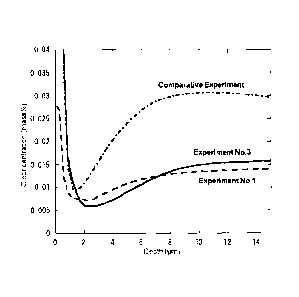
[Figure 1] Figure 1 is a graph showing C concentrations in the outer layer
portion on the tube inner surface side.
MODE FOR CARRYING OUT THE INVENTION
[0032]
1. Thickness of film formed on inner surface of tube
Since the Ni elution resistance depends on the thickness of a chromium
oxide film, the film thickness must be controlled. If the film thickness is
smaller than 0.05 m, the Ni elution resistance is insufficient. Although the
corrosion resistance is achieved by forming a film with thickness of 0.05 pm
or
larger, the film thickness is preferably 0.1 pm or larger. On the other hand,
for a high-Ni alloy in which the Ni content exceeds 40%, the film thickness is
preferably 0.2 IIM or larger, further preferably 0.3 m or larger.
[0033]
However, the increase of film thickness likely to lead the abrasion of film
and the abrasion occurs remarkably if the thickness exceeds 1.5 pan.
Therefore, the film thickness is made 1.5 ptm or smaller. The upper limit of
film thickness is preferably 0.95 m, further preferably 0.85 pun.
[0034]
2. Variations in film thickness
If the variations in film thickness in the longitudinal direction of tube
are large, and a film having a small thickness is formed locally, the Ni
elution
amount increases in that area. Therefore, the variations in film thickness are
preferably minimized. That is, the thickness of chromium oxide film should
satisfy the relationship defined by Formula (i).
0.4 61/82 2.5 ... (i)
in which 81 and 62 are thicknesses ( m) of the chromium oxide film at both
ends of tube, respectively.
- 10 -
CA 02807525 2013-02-05
[0035]
Formula (i) is preferably
0.5 81/82 2.0
further preferably
0.70 M/82 < 1.55
[0036]
In the film forming treatment of the Cr-containing austenitic alloy tube,
since the tube is heat-treated at the length of product to be shipped, after
the
heat treatment, specimens are cut out of both the end portions of product
tube,
and the film thicknesses are determined.
[0037]
3. Atmospheric gas fed into tube
In the method for producing the Cr-containing austenitic alloy tube of
the present invention, a chromium oxide film is formed on the inner surface of
the Cr-containing austenitic alloy tube by heating the Cr-containing
austenitic
alloy tube by using an atmospheric gas consisting of water vapor and
nonoxidizing gas.
[0038]
In order to oxidize only chromium present on the inner surface of tube, it
is necessary to make the interior of tube a low oxygen potential environment.
It is thought that, in such an environment, the feed of oxidizing gas
determines the rate of oxidation reaction. On the other hand, when the
atmospheric gas is fed into the tube, a concentration gradient occurs, and it
is
thought that the gas diffusibility at this time depends on the concentration
of
oxidizing gas and the flow rate of atmospheric gas. The feed of oxidizing gas
depends on the gas diffusibility, and therefore it can be thought that the
feed
of oxidizing gas also depends on the concentration of oxidizing gas and the
flow
rate of atmospheric gas.
- 11 -
CA 02807525 2013-02-05
[0039]
For example, in the case where carbon dioxide gas is used as the
oxidizing gas or in the case where an organic substance such as oil adheres to
the inner wall of tube, if a gas having a C source comes into contact with and
reacts with the surface of alloy, the concentration of C in the outer layer of
alloy is sometimes very slightly higher than the concentration of C in the
base
metal. If the concentration of C increases, the grain boundary strength of the
outer layer portion enhances, so that stress corrosion cracking may occur. In
the present invention, it is defined that the average concentration of C in
the
depth range of 5 to 10 i_tm from the inner surface is lower than the
concentration of C in the base metal. The average concentration of C in the
depth range of 5 to 10 p.m from the inner surface is a value obtained by
calculating the concentrations in the range of 5 to 10 lain at pitches of 0.1
i.im
or smaller in the conventional depth analysis (GDS, XPS, SIMS), and by
averaging these calculated concentrations. Also, to obtain the concentration
of C in the base metal, an analysis value obtained by the infrared absorption
method after high-frequency combustion using a chip specimen sampled from
the wall thickness central portion of tube is used. In order to obtain the
alloy
outer layer portion having such a C concentration, it is preferable that an
atmospheric gas containing water vapor be used as the atmospheric gas fed
into the tube, and further the interior of tube be cleaned (for example,
degreased) in advance.
[0040]
The concentration of carbon dioxide gas in the atmospheric gas is
preferably restricted to low level. When carbon dioxide is mixed in as an
impurity, the amount thereof is preferably 50 ppm or smaller.
[0041]
- 12 -
CA 02807525 2013-02-05
In the present invention, by making the water vapor concentration in
the atmospheric gas and the flow rate of the atmospheric gas in a proper
range,
an oxide film having a uniform film thickness can be formed.
[0042]
<Atmospheric gas>
If being contained even in a minute amount, water vapor forms the
chromium oxide film. Therefore, the lower limit thereof is not defined
especially. However, if 250 ppm or more of water vapor is contained, the
effect thereof becomes remarkable. The
upper limit of water vapor
concentration is not defined especially; however, the water vapor
concentration
is preferably 25,000 ppm or less from the viewpoint of reducing the production
cost.
[0043]
Further, in the present invention, as the oxidizing gas, oxygen may be
fed partially in addition to water vapor. Like water vapor, oxygen can form
the chromium oxides. The content of oxygen gas is preferably 10,000 ppm or
less. This is because, if oxygen is contained in a large amount, the formation
of chromium oxide film is accelerated, and the Cr concentration in the base
metal is decreased, so that the corrosion resistance is deteriorated. If being
contained even in a minute amount, oxygen achieves the above-described effect.
Therefore, the lower limit thereof is not defined especially; however, the
effect
thereof becomes remarkable when 0.0001 vol% or more of oxygen is contained.
[0044]
As the nonoxidizing gas, for example, hydrogen gas, rare gas (Ar, He,
etc.), carbon monoxide gas, nitrogen gas, hydrocarbon gas, and the like are
cited. When carbon monoxide gas, nitrogen gas, or hydrocarbon gas of these
nonoxidizing gases is used, there is a fear of carburizing and nitriding.
- 13 -
CA 02807525 2013-02-05
Therefore, at least one kind of hydrogen gas and rare gas is preferably
contained.
[0045]
Hydrogen gas is often used as an atmospheric gas for heat treatment on
an industrial scale. If this gas is used for dilution of water vapor gas, the
production cost can be reduced. Therefore, it is most favorable that heat
treatment is performed with the atmospheric gas being a gas atmosphere
consisting of water vapor gas and hydrogen gas.
[0046]
When hydrogen gas is used at least partially, by feeding oxygen as an
oxidizing gas, hydrogen and oxygen are caused to react with each other to
produce water, and water may be used for oxidation of tube. In this case,
attention must be paid to explosion.
[0047]
The concentration of atmospheric gas in the case where water vapor is
contained can be controlled by regulating the water vapor concentration by
dew point control after the concentrations of water vapor gas and nonoxidizing
gas or further oxygen gas have been regulated. Also, after the dew point has
been regulated by using the nonoxidizing gas, water vapor gas or further
oxygen gas may be added.
[0048]
<Flow rate of atmospheric gas fed into tube inner surface>
The flow rate of atmospheric gas fed into the inner surface of tube is
preferably 6.0 to 50 L/min. If the flow rate thereof is lower than 6.0 L/min,
even if the water vapor concentration and the heating condition are regulated,
an oxide film having a desired thickness cannot be formed. On the other
hand, if the flow rate thereof exceeds 50 L/min, inversely, the oxide film
becomes excessively thick.
- 14 =
CA 02807525 2013-02-05
[0049]
4. Length and inside diameter of tube
The Cr-containing austenitic alloy tube produced at the water vapor
concentration and under the heat treatment conditions defined in the present
invention is suitable as a steam generator tubing for nuclear power plant
having a tube length of 5 to 50 m and a tube inside diameter of 10 to 30 mm.
[0050]
In the case where the atmospheric gas is a highly diffusible gaseous
mixture of water vapor and nonoxidizing gas, the film thickness tends to vary
greatly. In the present invention, even if the atmospheric gas is a gaseous
mixture of water vapor and nonoxidizing gas, the variations in the oxide film
thickness on the inner surface of tube can be reduced by properly regulating
the water vapor concentration and the gas flow rate according to the length
and inside diameter of tube.
[0051]
5. Heat treatment temperature and heat treatment time
The heat treatment temperature and heat treatment time are not
limited. However, for example, the heating temperature can be in the range
of 800 to 1200 C and the heating time can be in the range of one minute or
longer. The reasons for restrictions are as described below.
[0052]
<Heating temperature>
The heating temperature may be in such a range that the proper
thickness and composition of oxide film and the strength characteristics of
alloy can be attained. Specifically, when the heating temperature is lower
than 800 C, the oxidation of chromium may be insufficient. In order to obtain
a film having a proper thickness in a proper time period, the heating
temperature is preferably 900 C or higher, further preferably 1000 C or
higher.
- 15-
CA 02807525 2013-02-05
On the other hand, the upper limit of heating temperature is 1200 C. If the
heating temperature exceeds 1200 C, there is a risk that the strength of the
Cr-containing austenitic alloy tube material cannot be ensured. Therefore,
the heating temperature should be in the range of 800 to 1200 C.
[0053]
<Heating time>
The heating time may be set in such a range that proper thickness and
composition of oxide film can be attained. That is, in order to form an oxide
film consisting mainly of chromium oxides, it is desirable to heat the tube
for
one minute or longer. The upper limit of heating time is not defined
especially. However, at least in the preferable heating temperature range of
800 to 1200 C of the present invention, even if the tube is heated for a time
period exceeding 24 hours, an oxide film is scarcely produced, and such
heating
time is disadvantageous in terms of production cost as well. Therefore, the
heating time should be in the range of one minute to 24 hours.
[0054]
In the case where the film forming treatment is performed in a
continuous heat treatment furnace, it is necessary that the heating time be
shortened to improve the productivity. The higher the heating temperature is,
the shorter the heating time can be made. Therefore, in order to form a film
having the thickness of the present invention, the heating temperature is in
the range of 1000 to 1200 C, and the heating time is preferably in the range
of
one to 60 minutes, further preferably in the range of one to 20 minutes.
[0055]
6. Chemical composition of material tube for Cr-containing austenitic alloy
tube
The chemical composition of a material tube for the Cr-containing
austenitic alloy tube for the production method of the present invention
should
- 16 -
CA 02807525 2013-02-05
be, for example, by mass percent, C: 0.15% or less, Si: 1.00% or less, Mn:
2.0%
or less, P: 0.030% or less, S: 0.030% or less, Cr: 10.0 to 40.0%, Ni: 8.0 to
80.0%,
Ti: 0.5% or less, Cu: 0.6% or less, Al: 0.5% or less, and N: 0.20% or less,
the
balance being Fe and impurities.
[0056]
The "impurities" are herein elements that mixedly enter on account of
various factors in the production process including raw materials such as ore
or scrap when an alloy is produced on an industrial scale, and are allowed to
be contained within the range such that the elements do not exert an adverse
influence on the present invention.
[0057]
The reason why the content of each element is restricted is explained
below. In the explanation below, the symbol "%" of the content of each
element means "mass percent".
[0058]
C: 0.15% or less
C (carbon) may deteriorate the stress corrosion cracking resistance if
being contained exceeding 0.15%. Therefore, if C is contained, the content
thereof is preferably 0.15% or less, further preferably 0.06% or less. On the
other hand, C has an effect of enhancing the grain boundary strength of alloy.
In order to achieve this effect, it is preferable that the C content is 0.01%
or
more.
[0059]
Si: 1.00% or less
Si (silicon) is used as a deoxidizer at the time of smelting, and remains
in the alloy as an impurity. At this time, the Si content should be restricted
to 1.00% or less. If the Si content exceeds 0.50%, the cleanliness of alloy
may
decrease. Therefore, the Si content is preferably restricted to 0.50% or less.
- 17 -
CA 02807525 2013-02-05
[0060]
Mn: 2.0% or less
Mn (manganese) decreases the corrosion resistance of alloy if being
contained exceeding 2.0%. Therefore, the Mn content is preferably 2.0% or
less, further preferably 1.0% or less. As compared with Cr, Mn has a low free
energy for formation of oxides, and precipitates as MnCr204 due to heating.
Also, since the diffusion velocity is relatively high, usually, Cr203 is
produced
preferentially in the vicinity of base metal by heating, and on the outside
thereof, MnCr204 is formed as an upper layer. If the MnCr204 layer is
present, the Cr203 layer is protected in the service environment, and even if
the Cr203 layer is broken for any reason, the restoration of Cr203 is
accelerated
by MnCr204. Such an effect becomes remarkable when 0.1% or more of Mn is
contained.
[0061]
13: 0.030% or less
P (phosphorus) is an element that is present in the alloy as an impurity.
If the P content exceeds 0.030%, the corrosion resistance may be adversely
affected. Therefore, the P content is preferably restricted to 0.030% or less.
[0062]
S: 0.030% or less
S (sulfur) is an element that is present in the alloy as an impurity. If
the S content exceeds 0.030%, the corrosion resistance may be adversely
affected. Therefore, the S content is preferably restricted to 0.030% or less.
[0063]
Cr: 10.0 to 40.0%
Cr (chromium) is an element necessary for producing an oxide film
consisting of chromium oxides. In order to produce such an oxide film on the
surface of alloy, it is desirable to contain 10.0% or more of Cr. However, if
the
- 18 -
CA 02807525 2013-02-05
Cr content exceeds 40.0%, the workability may be deteriorated. Therefore,
the Cr content is preferably 10.0 to 40.0%.
[0064]
Ni: 8.0 to 80.0%
Ni (nickel) is an element necessary for ensuring the corrosion resistance
of the Cr-containing austenitic alloy, and 8.0% or more of Ni is preferably
contained. On the other hand, since Ni is expensive, the minimum necessary
amount of Ni has only to be contained depending on the intended use, and the
Ni content is preferably 80.0% or less.
[0065]
Ti: 0.5% or less
Ti (titanium) may decrease the cleanliness of alloy if the content thereof
exceeds 0.5%. Therefore, the Ti content is preferably 0.5% or less, further
preferably 0.4% or less. However, it is desirable to contain 0.1% or more of
Ti
from the viewpoints of improvement in workability of alloy and restraint of
grain growth at the time of welding.
[0066]
Cu: 0.6% or less
Cu (copper) is an element that is present in the alloy as an impurity. If
the Cu content exceeds 0.6%, the corrosion resistance of alloy may decrease.
Therefore, it is desirable to restrict the Cu content to 0.6% or less.
[0067]
Al: 0.5% or less
Al (aluminum) is used as a deoxidizer at the time of steel making, and
remains in the alloy as an impurity. The remaining Al turns to be an oxide-
base inclusion in the alloy, decreases the cleanliness of alloy, and may exert
an
adverse influence on the corrosion resistance and mechanical properties of
alloy. Therefore, it is desirable to restrict the Al content to 0.5% or less.
- 19 -
CA 02807525 2013-02-05
[0068]
N: 0.20% or less
N (nitrogen) need not be contained, but about 0.01% of N is usually
contained as an impurity in the Cr-containing austenitic alloy, which is an
object of the present invention. However, if N is added positively, the
strength can be enhanced without deteriorating the corrosion resistance. On
the other hand, if the N content exceeds 0.20%, the corrosion resistance
decreases. Therefore, the upper limit of the content of N, if contained, is
0.20%.
[0069]
Among the above Cr-containing austenitic alloys, especially, a nickel-
based alloy having a chemical composition of C: 0.15% or less, Si: 1.00% or
less,
Mn: 2.0% or less, P: 0.030% or less, S: 0.030% or less, Cr: 10.0 to 40.0%, Ni:
45.0 to 80.0%, Ti: 0.5% or less, Cu: 0.5% or less, and Al: 0.5% or less, the
balance being Fe and impurities, is preferable. This is because this alloy is
further excellent in corrosion resistance.
[0070]
Two kinds of Cr-containing nickel-based alloy tubes having the typical
chemical compositions are as follows:
[0071]
(a) A Cr-containing nickel-based alloy tube consisting of C: 0.15% or less,
Si: 1.00% or less, Mn: 2.0% or less, 13: 0.030% or less, S: 0.030% or less,
Cr: 14.0
to 17.0%, Fe: 6.0 to 10.0%, Ti: 0.5% or less, Cu: 0.5% or less, and Al: 0.5%
or
less, the balance being Ni and impurities.
[0072]
(b) A Cr-containing nickel-based alloy tube consisting of C: 0.06% or less,
Si: 1.00% or less, Mn: 2.0% or less, 13: 0.030% or less, S: 0.030% or less,
Cr: 27.0
- 20 -
CA 02807525 2013-02-05
to 31.0%, Fe: 7.0 to 11.0%, Ti: 0.5% or less, Cu: 0.5% or less, and Al: 0.5%
or
less, the balance being Ni and impurities.
[0073]
The alloy of the item (a) is an alloy excellent in corrosion resistance in an
environment containing chlorides because of containing 14.0 to 17.0% of Cr
and 70 to 80% of Ni. In this alloy, the Fe content is preferably 6.0 to 10.0%
from the viewpoint of the balance between the Ni content and the Cr content.
[0074]
The alloy of the item (b) is an alloy excellent in corrosion resistance not
only in an environment containing chlorides but also in an environment of
pure water and alkali at high temperatures because of containing 27.0 to
31.0% of Cr and 55 to 65% of Ni. In this alloy as well, the Fe content is
preferably 7.0 to 11.0% from the viewpoint of the balance between the Ni
content and the Cr content.
[00751
7. Method for producing material tube for Cr-containing austenitic alloy tube
The method for producing a material tube for the Cr-containing
austenitic alloy tube, which is an object of the present invention, is carried
out
as described below. After a raw material having a predetermined chemical
composition has been melted to produce an ingot, a Cr-containing austenitic
alloy tube is usually produced through the steps of hot working and annealing
or the steps of hot working, cold working, and annealing. Further, to improve
the corrosion resistance of base metal, a special heat treatment called
thermal
treatment is sometimes performed.
[00761
The heat treatment of the present invention may be performed after the
annealing treatment, or may be performed combinedly with the annealing
treatment. If the heat treatment is performed combinedly with the annealing
- 21-
CA 02807525 2013-02-05
treatment, a heat treatment step for forming the oxide film need not be added
to the conventional production process, so that the production cost does not
increase. Also, in the case where thermal treatment is performed after
annealing as described above, the thermal treatment may be performed
combinedly with the heat treatment for forming the oxide film. Further, both
of annealing treatment and thermal treatment may be performed as a
treatment for forming the oxide film.
EXAMPLE 1
[0077]
A material tube used for an experiment was produced by the producing
method described below. First, an alloy having the chemical composition
given in Table 1 was melted and cast to obtain an ingot. This ingot was hot-
forged to produce a billet, and thereafter a tube was formed by a hot
extrusion
tube-making process. The tube thus obtained was cold-rolled by using a cold
pilger mill so as to have an outside diameter of 25.0 mm and a wall thickness
of 1.65 mm. Next, this cold-rolled tube was annealed in an hydrogen
atmosphere of 1100 C, and thereafter was finished, by the cold drawing
method, to a tube having a product size of 19.0 mm in outside diameter, 1.0
mm in wall thickness, and 20,000 mm in length (reduction of area = 53%).
Subsequently, the finished tube was cut to a necessary length, and thereafter
the inner and outer surfaces of each tube were washed with an alkali
degreasing liquid and rinse water, and the inner surface was further washed
with acetone.
[0078]
[Table 1]
- 22-
CA 02807525 2013-02-05
Table 1
Chemical composition (in mass%, balance: Fe and impurities)
Alloy=C Si Mn P S Cr Ni Ti Cu Al N
A 0,019 0.22 0.26 0.008 0.001 29.4 59.2 0.25 0.25 0.24 0.01 .
[0079]
While an atmospheric gas having a predetermined flow rate was fed to
the obtained tube via a header, the tube was heated in a heating furnace while
being moved, whereby a chromium oxide film was formed on the inner surface
of tube.
[0080]
Both ends of the heat-treated tube were cut, and the film composition
was examined by using an energy dispersive X-ray micro-analyzer (EDX). As
the result, it was found that an oxide film consisting of chromium oxides had
been formed. The film was analyzed by using glow discharge optical emission
spectroscopy (GDS), and the thickness from the outermost surface to a position
at which the intensity of peak of observed oxygen reduced by half was defined
as a film thickness. Taking the thicknesses at the gas inlet and the gas
outlet
as 81 and 82, respectively, and taking a variation in thickness at both ends
as
81/82, evaluation was carried out. The evaluation results are given in Table 2
[00811
[Table 2]
- 23 -
Table 2
Heating 1000 C
Results
Concent- Flow Tube Tube
Test tempe-
holding Film thickness Thickness C concentration
ration rate length diameter
No. rature time entrance exit side
distribution (mass%)
(ppm) (L/min) (m) (mm) (.0
(mm) n side (pm) (pm) (61/82) Surface.
1 3000 10 20 17 1100 5 0.70 0.60
1.2 0.013
2 6000 10 20 17 1100 5 1.03 0.68
1.5 0.012
-
3 9000 10 20 17 1100 5 1.05 0.98
1.1 0.013
4 3960 18 20 17 1100 5 0.74 0_61
1.2 0.011 n
5 3960 12 20 17 1100 5 0.74 0.54
1.4 0.013 0
I.)
co
0
6 3960 6.0 20 17 1100 5 0.74 0.30
2.5 0.017
Ul
NJ
7 * 3960 4.5 * 20 17 1100 5 0.74 0.10 7.4
* 0.015 in
N.Div
8 * 240 * 10 20 17 1100 5 0.07 0.02 * 3.5
* 0.014 0
H
UJ
9 16800 6.0 20 17 1100 5 1.40 1.14
1.2 0.009 I0
NJ
10 * 9000 5.6 * 20 17 1100 5 1.10
0.40 2.8 * 0.009 I0
Ul
11 1000 10 20 17 1100 5 0.31 0.13
2.4 0.015
12 500 30 20 17 1100 5 0.18 0.13
1.4 0.015
13 24800 10 20 17 1100 5 1.50 1.32 1.1 0.009
14 2240 9.8 20 17 1100 5 0.53 0.29
1.8 0.012
15 4560 6.0 20 17 1100 5 0.80 0.36
2.2 0.013
t indicates comparative examples.
* indicates that conditions do not satisfy those defined by the present
invention.
' indicates the average concentration of C in the depth range of 5 to 10 pm
from the surface layer
at the tube inner surface side.
CA 02807525 2013-02-05
[0082]
From Table 2, it is apparent that the average film thickness of example
embodiment of the present invention is in the range of 0.05 to 1.5 um, and the
film thickness distribution falls into an intended range. Also, it is apparent
that by regulating the flow rate and water vapor concentration of the
atmospheric gas to the range defined in the present invention, proper film
thickness range and distribution can be obtained even by water vapor
treatment. In particular, if the flow rate of atmospheric gas is 6.0 L/min or
higher, an oxide film having an intended film thickness and thickness
distribution can be formed in a wide range of water vapor concentration.
[0083]
Figure 1 shows the results of distribution of C concentration obtained by
using GDS in experiment Nos. 1 and 3 and comparative experiments.
[0084]
In comparative experiment, the austenitic alloy tube was treated at a
heating time of 1100 C for a holding time of five minutes with flowing
hydrogen containing 5,600 ppm of carbon dioxide gas at a flow rate of 9.0
L/min, and a chromium oxide film was formed on the surface thereof.
[0085]
In both of experiment Nos. 1 and 3 of the present invention, it is
apparent that each of the average C concentration was 0.013% in the depth
range of 5 to 10 pm from the inner surface, and lower than the concentration
of
base metal of 0.019%. In contrast, if carbon dioxide gas was used as an
oxidizing gas, the result was such that the average C concentration in the
surface layer was 0.027%, which is higher than the C concentration of base
metal of 0.019%. If C is present exceeding the base metal concentration of C
contained to enhance the grain boundary strength, a possibility of occurring
stress corrosion cracking becomes high. In the water vapor treatment, the C
- 25 -
CA 02807525 2013-02-05
concentration decreases properly in the vicinity of the surface, so that the
tube
can be used more safely as a product material.
EXAMPLE 2
[0086]
Next, to examine the influence of parameter, Cr-containing austenitic
alloy tubes having changed tube diameter and tube length were prepared, and
a chromium oxide film was formed under the conditions given in Table 3 by
using the same method as that of Example 1. The results are given in Table 3.
[0087]
[Table 3]
- 26 -
a--,'
(=>
cc Table 3
co
Heating 1000 C
Results
Concent- Flow Tube Tube
Test
tempe- holding Film thickness Thickness C concentration
ration rate length diameter
No. rature time
entrance exit side distribution (mass%)
(ppm) (L/min) i n ) (m) (ram) (.0 (mm) _
side (urn) (pm) (81/62) Surface..
16 2750 18 20 10 1100 5
0.60 0.51 1.2 0.012
17 2750 18 20 17 , 1100 5
0.60 0.43 1.4 0.014
18 2750 18 20 25.4 1100 5
0.60 0.33 1.8 0.016
19 2750 18 20 30 1100 5
0.60 0.28 2_1 0.016 n
20 1980 12 20 12.5 1100 5
0.49 0.29 1.7 0.016 0
I.)
co
21 7500 10.0 20 14.5 1100 5
1.06 0.84 1.3 0.010 0
-.1
Ul
22 3960 12.0 10 17 1100 5
0.78 0.64 1.2 0.018 I.)
u-,
ND 23 3960 12 20 17 1100 5
0.74 0.54 1.4 0.013 I.)
0
H
---1
UJ
I
24 3960 12.0 30 17 1100 5
0.74 0.50 1.5 0.014 0
IV
I
' indicates the average concentration of C in the depth range of 5 to 10 pm
from the surface layer 0
Ul
at the tube inner surface side.
CA 02807525 2013-02-05
Table 3 indicates that if the heat treatment conditions defined in the
present invention were satisfied, the average film thickness of the obtained
chromium oxide film was within the range of 0.05 to 1.5 m, and the film
thickness distribution also fell into the intended range. If the inside
diameter
of tube is within the range of 10 to 30 mm, a Cr-containing austenitic alloy
tube provided with a chromium oxide film having proper film thickness range
and distribution can be prepared. Further, concerning the influence of tube
length, by properly regulating the concentration of water vapor and the flow
rate of atmospheric gas, even if the tube is as long as 30 m, a chromium oxide
film such that both of the film thickness range and distribution fall into the
defined range of the present invention can be formed in the tube.
EXAMPLE 3
[0089]
An alloy tube (tube length: 20 m, tube diameter: 17 mm) having the
chemical composition given in Table 4 was oxidized with water vapor, and
thereby a chromium oxide film was formed. The film forming conditions were
set in the same way as in experiment No. 5. That is, hydrogen containing
3,960 ppm of water vapor was flowed at a flow rate of 12 L/min as an
atmospheric gas, and the heat treatment temperature was set at 1100 C and
the treatment time was set at five minutes. The measurement results of film
thickness and C concentration of a specimen after treatment are given in Table
5.
[0090]
[Table 4]
- 28 -
CA 02807525 2013-02-05
Table 4
Chemical composition (in mass%, balance: Fe and impurities)
Alloy
C Si Mn P S Cr Ni Ti Cu Al N
B 0.031 0.29
0.30 0.008 <0.001 16.1 72.5 0.21 0.02 0.11 0.02
C 0.020 0.47 0.60 0.007 <0.001
21.3 34.3 - 0.02 - 0.01
D 0.061 0.39 1.54 0.022 0.001 18.5
10.0 - 0.02 - 0.02
[0091]
[Table 5]
Table 5
Results
Film thickness Thickness C concentration
Alloy
entrance exit side distribution (mass%)
side (pm) (pm) (81/82) Surface**
A 0.74 0.54 1.4 0.013
0.70 0.44 1.6 0.019
0.80 0.50 1.6 0.015
0.75 0.47 1.6 0.042
** indicates the average concentration of C in the depth
range of 5 to 10 pm from the surface layer at the tube
inner surface side.
[0092]
Compared with the result for alloy A in Examples 1 to 3, for alloys B, C
and D, substantially equivalent results were obtained in both of film
thickness
and distribution. Also, for the alloys having any chemical composition, it was
confirmed that the average C concentration in the surface layer was lower
than the C concentration of base metal.
INDUSTRIAL APPLICABILITY
[0093]
- 29 -
CA 02807525 2013-02-05
According to the present invention, a Cr-containing austenitic alloy tube
in which a chromium oxide film is formed at a low cost and uniformly on the
inner surface of tube can be obtained. Even if the Cr-containing austenitic
alloy tube is used in a high-temperature water environment, for example, in a
nuclear power plant for a long period of time, the elution of Ni is very
little.
Therefore, the Cr-containing austenitic alloy tube is best suitable as a
member
used in high-temperature water, such as a steam generator tubing, especially
as a member for nuclear power plant.
- 30 -