Note: Descriptions are shown in the official language in which they were submitted.
CA 02807562 2015-09-29
Method of Resource Allocation and Signaling
for Aperiodic Channel Sounding
BACKGROUND
[0001] As used herein, the terms "user equipment" and "UE" might in some
cases refer
to mobile devices such as mobile telephones, personal digital assistants,
handheld or
laptop computers, and similar devices that have telecommunications
capabilities. Such a
UE might consist of a device and its associated removable memory module, such
as but
not limited to a Universal Integrated Circuit Card (UICC) that includes a
Subscriber Identity
Module (SIM) application, a Universal Subscriber Identity Module (USIM)
application, or a
Removable User Identity Module (R-UIM) application. Alternatively, such a UE
might
consist of the device itself without such a module. In other cases, the term
"UE" might refer
to devices that have similar capabilities but that are not transportable, such
as desktop
computers, set-top boxes, or network appliances. The term "UE" can also refer
to any
hardware or software component that can terminate a communication session for
a user.
Also, the terms "user equipment," "UE," "user agent," "UA," "user device" and
"user node"
might be used synonymously herein.
[0002] Al-so as used herein, "higher layer signaling" refers to control
messages that
originate in higher protocol layers than the physical layer and that control
the operation of
the physical layer. Such messages are typically carried on physical channels
other than
physical control channels. Higher layer signaling is sent relatively
infrequently to a UE,
perhaps a few messages per second or less. Higher layer signaling that allows
physical
layer parameters to be set or changed at these rates is referred to as being
"semi-static".
[0003] By contrast, "dynamic signaling" as used herein refers to signaling
that is sent
frequently to control the physical layer. Such signaling comprises relatively
small numbers
of information bits, and may be sent continuously to a UE. Dynamic signaling
is often
carried on physical control channels that are optimized for the small size and
tight delay
requirements found in dynamic signaling.
[0004] As contemplated herein, UEs may be addressed individually in a "UE-
specific"
manner or as a group of UEs served by a cell in a "cell-specific" manner. A
"UE-specific"
message is therefore a message that is transmitted to a UE and intended to be
used only
by that UE. A "cell-specific" message is therefore a message transmitted to
the group of
1
CA 02807562 2015-03-16
UEs served by a cell that is intended to be used by all UEs in the cell. While
cell-specific
signaling is most often broadcast to multiple UEs that receive it
simultaneously, it can also
be sent to the different UEs at different times. Similarly, a UE-specific
physical layer
resource is one that is allocated to that UE, whereas a cell-specific physical
layer resource
may be allocated to multiple UEs in a cell. Furthermore, a UE-specific
information element
or parameter is information that is to be used by that UE, whereas a cell-
specific
information element or parameter is information that is to be used by all UEs
served by a
cell.
[0006] As telecommunications technology has evolved, more advanced network
access
equipment has been introduced that can provide services that were not possible
previously. This network access equipment might include systems and devices
that are
improvements of the equivalent equipment in a traditional wireless
telecommunications
system. Such advanced or next generation equipment may be included in evolving
wireless communications standards, such as long-term evolution (LTE). For
example, an
LTE system might include an Evolved Universal Terrestrial Radio Access Network
(E-
UTRAN) node B (eNB), a wireless access point, or a similar component rather
than a
traditional base station. As used herein, the term "access node" will refer to
any
component of the wireless network, such as a traditional base station, a
wireless access
point, or an LTE eNB, that creates a geographical area of reception and
transmission
coverage allowing a UA or a relay node to access other components in a
telecommunications system. An access node may comprise a plurality of hardware
and
software. LTE may be said to correspond to Third Generation Partnership
Project (3GPP)
Release 8 (Re1-8 or R8) and Release 9 (Re1-9 or R9) while LTE-A may be said to
correspond to Release 10 (Re1-10 or R10) and possibly to releases beyond
Release 10.
[0006]
The uplink (UL) refers to the communication link from the UE to the access
node, and the downlink (DL) refers to the communication link from the access
node to the
UE. A UL grant is a control message on a physical control channel provided by
the access
node to the UE allowing it to transmit data to the access node. A DL grant is
a control
message on a physical control channel provided by the access node to the UE
indicating to
the UE that the access node will transmit data to the UE.
2
CA 02807562 2015-03-16
BRIEF DESCRIPTION OF THE DRAWINGS
[0007] For a more complete understanding of this disclosure, reference is
now made to
the following brief description, taken in connection with the accompanying
drawings and
detailed description, wherein like reference numerals represent like parts.
[0008] Figure 1 illustrates the location of the sounding reference signal
(SRS) in an LTE
subframe.
[0009] Figure 2 illustrates an LTE Re1-8 sounding reference signal subframe
configuration.
[0010] Figure 3 illustrates an example of an LTE system with mixed Re1-8
UEs with a
single transmission antenna and Re1-10 UEs with multiple transmission
antennas,
according to an embodiment of the disclosure.
[0011] Figure 4 illustrates an LTE Re1-8 cell-specific SRS configuration
information
element (1E).
[0012] Figure 5 illustrates a cell-specific periodic SRS configuration 1E,
according to an
embodiment of the disclosure.
[0013] Figure 6 illustrates a subframe-based SRS resource partition,
according to an
embodiment of the disclosure.
[0014] Figure 7 illustrates the timing of a multi-shot aperiodic SRS
transmission,
according to an embodiment of the disclosure.
[0015] Figure 8 illustrates a signaling example in supporting aperiodic
SRS, according
to an embodiment of the disclosure.
[0016] Figure 9 illustrates a bit-map based periodic srs subframe
configuration,
according to an embodiment of the disclosure.
[0017] Figure 10 illustrates a bit-map based aperiodic srs subframe
configuration,
according to an embodiment of the disclosure.
[0018] Figure 11 illustrates a Re1-8 UE-specific SRS configuration 1E.
[0019] Figure 12 illustrates a UE-specific aperiodic SRS configuration 1E,
according to
an embodiment of the disclosure.
[0020] Figure 13 illustrates a UE-specific aperiodic SRS configuration IE
for a shared
periodic and aperiodic resource, according to an embodiment of the disclosure.
3
CA 02807562 2015-03-16
[0021] Figure 14 illustrates frequency hopping support for aperiodic SRS,
according to
an embodiment of the disclosure.
[0022] Figure 15 illustrates a UE-specific aperiodic SRS configuration
example with five
UEs, according to an embodiment of the disclosure.
[0023] Figure 16a illustrates cell-specific SRS subframes, according to an
embodiment
of the disclosure.
[0024] Figure 16b illustrates frequency domain locations for aperiodic SRS
transmission, according to an embodiment of the disclosure.
[0025] Figure 17 illustrates an example of dynamic aperiodic SRS resource
signaling
with four bits, according to an embodiment of the disclosure.
[0026] Figure 18 illustrates another example of dynamic signaling of
aperiodic SRS with
four bits, according to an embodiment of the disclosure.
[0027] Figure 19 illustrates a method for resource allocation, according to
an
embodiment of the disclosure.
[0028] Figure 20 illustrates a processor and related components suitable
for
implementing the several embodiments of the present disclosure.
DETAILED DESCRIPTION
[0029] It should be understood at the outset that although illustrative
implementations of
one or more embodiments of the present disclosure are provided below, the
disclosed
systems and/or methods may be implemented using any number of techniques,
whether
currently known or in existence. The disclosure should in no way be limited to
the
illustrative implementations, drawings, and techniques illustrated below,
including the
exemplary designs and implementations illustrated and described herein, but
may be
modified within the scope of the appended claims along with their full scope
of equivalents.
[0030] Channel sounding is sometimes used in wireless communication systems
to
obtain uplink channel state information for assigning modulation and coding
schemes, for
frequency selective scheduling of uplink transmissions, and, in the case of
multiple
input/multiple output (MIMO) operation, for selecting a rank and an antenna
precoding
matrix. In this technique, a known sounding signal waveform is typically
transmitted
between a transmitter and a receiver, and the channel state information is
estimated at the
receiver based on the known sounding signal. In 3GPP LTE Re1-8, a sounding
reference
4
CA 02807562 2015-03-16
signal (SRS) is typically transmitted periodically from each connected UE to
an access
node to facilitate uplink timing correction, scheduling, and link adaptation.
[0031] 3GPP LTE defines system timing in terms of subframes and radio
frames.
Subframes are one millisecond long, whereas radio frames are 10 milliseconds
long.
Radio frames are numbered by system frame indices ranging from 0 to 1023. One
or more
subframes in a frame of ten subframes might be designated as subframes in
which an SRS
might be transmitted. In a subframe that has been configured for SRS
transmission, the
last symbol of the subframe is typically used for SRS transmission, as shown
in Figure 1.
[0032] In Re1-8, UE-specific SRS resources are defined in the frequency,
time, and
code domains in terms of UE-specific SRS bandwidth, frequency domain position,
transmission comb, cyclic shift, subframe periodicity, and subframe offset.
Cell-specific
SRS resources are defined in both the frequency and time domains in terms of
SRS
periodicity, subframe offsets, and SRS bandwidth and are semi-statically
configured in a
cell. The cell-specific subframe configuration is shown in Figure 2 and is
indicated by "srs-
SubframeConfig". SRS subframes are the subframes satisfying bis 2 jmodTsõ E
SFC where
n,= 0, 1, . . . , 19 is the slot index within a frame.
[0033] For example, for srs-SubframeConfig 0 in row 210 of Figure 2, the
configuration
period in column 250 is 1 and the offset in column 260 is 0. The period of 1
means that
every subframe in a frame of ten subframes is configured for SRS transmission.
For srs-
SubframeConfig 1 in row 220, the configuration period is 2 and the offset is
0. Therefore,
every second subframe starting with subframe 0 is configured for SRS
transmission in this
case. For srs-SubframeConfig 2 in row 230, the configuration period is 2 and
the offset is
1. Therefore, every second subframe starting with subframe 1 is configured for
SRS
transmission. As another example, srs-SubframeConfig 5 in row 240 has a
configuration
period of 5 and an offset of 2. Therefore, every fifth subframe starting with
subframe 2 is
configured for SRS transmission. It can be seen that for Re1-8, the SRS
configurations are
periodic, with a plurality of different periodicities being available.
[0034] In LTE Rel-10, it has been agreed that an aperiodic SRS will be
supported in
addition to the periodic SRS of Re1-8. That is, since a UE may not always have
data to
transmit in the uplink, in Rel-10 the SRS might be transmitted only when a UE
has data to
CA 02807562 2015-03-16
transmit. By use of such an aperiodic SRS transmission, fewer resources might
be used
and both SRS and system radio resource efficiency might be improved.
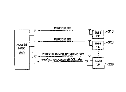
[0035] An example of such an LTE system is shown in Figure 3, where a first UE
310
and a second UE 320 are Re1-8 UEs, each with a single transmit antenna, and a
third UE
330 is a Re1-10 UE with two transmit antennas. In other embodiments, other
numbers of
Re1-8 and Re1-10 UEs could be present, and other numbers of antennas could be
present
on UE 330. UE 310 and UE 320 can transmit a periodic SRS to an access node
340.
Each antenna on UE 330 can transmit a periodic SRS, an aperiodic SRS, or both
to the
access node 340.
[0036]
While aperiodic SRS transmissions are allowed in Re1-10, details regarding the
sharing of periodic and aperiodic resources are not defined. Embodiments of
the present
disclosure address issues related to aperiodic SRS transmissions such as cell-
specific
resource partitioning between periodic and aperiodic SRS, higher layer
signaling of cell-
specific aperiodic SRS resource allocation, higher layer signaling of UE-
specific aperiodic
SRS resource allocation, frequency hopping with narrow-band aperiodic SRS
without
dynamic signaling, and efficient dynamic signaling of UE-specific aperiodic
SRS resource
allocation.
Some embodiments address these issues using a semi-static SRS
configuration, and other embodiments address these issues using dynamic
signaling of
SRS resources. The semi-static solutions may have less signaling overhead than
the
dynamic solutions, but may not be as flexible. The dynamic solutions may offer
more
flexibility but may have a larger signaling overhead than the semi-static
solutions.
[0037]
In an embodiment, methods and systems of partitioning resources between
periodic SRS and aperiodic SRS are provided. The Re1-8 cell-specific SRS
subframe
resources are divided into two parts, one for cell-specific periodic SRS and
the other for
cell-specific aperiodic SRS. The higher layer cell-specific SRS subframe
configuration that
is used in Re1-8 is used to inform UEs about the total SRS subframe resources.
For both
Re1-8 and Rel-10 UEs, this information is used by the UE to determine whether
or not the
last symbol of a subframe will be used for SRS transmission (either periodic
or aperiodic) in
order to avoid collisions between data and SRS transmissions. For Rel-10 UEs,
in addition
to the total cell-specific SRS resource allocation, the partition of the cell-
specific SRS
6
CA 02807562 2015-03-16
resources between periodic SRS transmission and aperiodic SRS transmission is
also
signaled through higher layers.
[0038] Such a technique of partitioning SRS subframes maintains the same
overall
SRS resource allocation capability as in Re1-8 in terms of percentage of
subframes and
subframe offsets configured for SRS. It allows flexible (but semi-static)
partitioning of the
total cell-specific SRS resources between periodic and aperiodic SRS. It also
enables
aperiodic SRS frequency hopping within the aperiodic partition without
dynamically
signaling the frequency domain resources.
[0039] In this technique, the cell-specific SRS configuration of Re1-8
shown in Figure 4
is used to configure the overall SRS subframes in a cell. The cell-specific
SRS subframes
are divided into two subsets, one for cell-specific periodic SRS and the other
for cell-
specific aperiodic SRS. This subframe partition is used only by Re1-10 UEs and
is signaled
using a new cell-specific periodic SRS configuration information element (1E)
within the
radio resource control (RRC) signaling as shown in Figure 5, or alternatively
a new cell-
specific aperiodic SRS configuration 1E is used. These IEs may be carried
within the
system information broadcast by the cell. The elements in Figures 4 and 5 will
be
described in more detail below.
[0040] Some possible subframe partitions between periodic SRS and aperiodic
SRS
are shown in Figure 6. For example, for partition #2 at row 610, srs-
SubframeConfig #0
from Figure 2 is broadcast to all the UEs served by the cell. That is, the
periodicity is 1,
meaning that all the subframes are configured for SRS transmission, as
indicated by the
presence of a letter in each subframe column in that row. UEs may transmit SRS
in those
subframes in the symbol allocated for SRS transmission. In addition, srs-
SubframeConfig
#2 from Figure 2 is used only by Re1-10 UEs to determine the partition between
periodic
and aperiodic SRS subframes. That is, srs-SubframeConfig #2 has a periodicity
of 2 and
an offset of 1. Therefore, every other subframe starting with subframe 1 is
designated for
periodic SRS, as indicated by the letter "p" in those subframes. The remaining
subframes
are designated for aperiodic SRS, as indicated by the letter "a" in those
subframes. In
other words, in this example, 100% of the subframes are configured as cell-
specific SRS
subframes, half of which are configured for periodic SRS (subframes # 1,3,
...) and the
other half for aperiodic SRS (subframes # 0,2, ...).
7
CA 02807562 2015-03-16
[0041] Using partition #47 at row 620 as another example, srs-
SubframeConfig #14 is
broadcast to all UEs. That is, as can be seen from Figure 2, srs-
SubframeConfig #14 has
a periodicity of 10 and an offset of {0,1,2,3,4,5,6,8}. Therefore, subframes
0, 1, 2, 3, 4, 5,
6, and 8 are configured for SRS transmission, as indicated by the presence of
a letter in
those subframe columns in that row. In addition, srs-SubframeConfig #4 is used
only by
Rel-10 UEs to determine the subframe partition. That is, as can be seen from
Figure 2,
srs-SubframeConfig #4 has a periodicity of 5 and an offset of 1. Therefore,
every fifth
subframe starting with subframe 1 is designated for periodic SRS transmission,
and the
other subframes that are configured for SRS transmission are designated for
aperiodic
SRS transmission. In this case, 80% of the subframes are configured for SRS,
with 20%
configured for periodic SRS and 60% configured for aperiodic SRS.
[0042] It can be seen from Figure 6 that such a partitioning method
provides many
possible combinations with different subframe usage ratios between periodic
and aperiodic
subframes, where srs-SubframeConfig # is used to inform all UEs about the
total cell-
specific SRS subframe configuration while periodic-srs-SubframeConfig # is
used to inform
Re1-10 UEs about the SRS subframes configured for periodic SRS. The table
shown in
Figure 2 and used in Re1-8 for cell-specific SRS subframe configuration is
used here. For
example, srs-SubframeConfig #0 means all subframes are configured for SRS
whereas
periodic-srs-SubframeConfig #0 means all subframes are configured for periodic
SRS.
This approach allows the access node to partition the SRS subframes between
periodic
and aperiodic SRS flexibly based on different deployment scenarios while
remaining
backward compatible to Re1-8 UEs.
[0043] It should be noted that the table in Figure 6 does not include an
exhaustive list of
all the possible combinations. Other combinations are also possible, such as
(srs-
SubframeConfig #, periodic-srs-SubframeConfig #) = (2,10) or (2,12).
[0044] The actual aperiodic SRS transmission by a UE could be triggered
using control
signaling on a physical downlink control channel (PDCCH). Either an uplink
grant or a
downlink grant may be used on the PDCCH. As shown in Figure 7, the actual
timing of the
transmission occurs at subframe n?_k+A, where k is the subframe at which the
triggering
is transmitted in downlink and A is a constant integer. A may be predefined,
for example
8
CA 02807562 2015-03-16
A=4. A is used because of processing delays. That is, when the UE receives the
trigger
in subframe k, it needs some time to formulate the transmission.
[0045] If the partition between periodic and aperiodic SRS is made on a
subframe
basis, then after receiving an SRS trigger in subframe k the UE checks if
subframe k + A
is configured for aperiodic SRS transmission (in cell-specific aperiodic SRS
subframes). If
subframe k + A is so configured, then the UE transmits an aperiodic SRS at
that subframe.
Otherwise, the aperiodic SRS transmission will occur at the first subframe
that is
configured for aperiodic SRS transmission after subframe k + A.
[0046] In the case where a multi-shot aperiodic SRS is triggered, the
subsequent
aperiodic SRS transmissions after the first transmission occur on the
subsequent aperiodic
SRS subframes immediately after the subframe used for the first transmission.
This is
shown in Figure 7, where a burst of four SRS transmissions is assumed for the
multi-shot
aperiodic SRS. The aperiodic SRS trigger is carried in subframe k, and the
first aperiodic
SRS transmission is at subframe n = k+7, assuming A = 4, because subframes k+5
and
k+6 are not configured for aperiodic SRS. The subsequent three SRS
transmissions occur
at subframes k+9, k+10 and k+12 because subframes k+8 and k+11 are not
configured for
aperiodic SRS.
[0047] In an embodiment, the cell-specific SRS resource as defined in Re1-8
continues
to be signaled to Re1-8 UEs. For Re1-10 UEs, in addition to such signaling,
the partition of
periodic and aperiodic SRS is signaled. Such partition information can be
signaled by
informing the Re1-10 UEs of either the periodic SRS subframes or the aperiodic
SRS
subframes. If periodic subframes are signaled, the remaining SRS subframes are
assumed to be aperiodic. If aperiodic subframes are signaled, the remaining
SRS
subframes are assumed to be periodic. It may be preferable to inform the Re1-
10 UEs of
the periodic SRS subframes because the Re1-8 subframe configuration can be
reused and
no new SRS subframe definition is required.
[0048] Because Re1-8 signaling of the SRS subframe configuration is used to
inform all
UEs served by a cell about the total SRS subframe resources, Re1-8 UEs that
are not
capable of aperiodic SRS transmission can be instructed by the access node to
transmit
periodic SRS in any of the SRS subframes. This means that Re1-8 UEs could
transmit in
subframes that contain aperiodic SRS transmissions from Re1-10 UEs. The access
node
9
CA 02807562 2015-03-16
=
prevents this conflict by instructing Re1-8 UEs to transmit their periodic SRS
transmissions
in periodic subframes, rather than aperiodic subframes. This is accomplished
by setting
each Re1-8 UE's UE-specific periodicity, Tsrs, and its UE-specific subframe
offset, Toffset,
such that each of its SRS transmissions is confined within periodic subframes.
For
example in Figure 6, Re1-8 UEs configured for partition #2 at row 610 will
have srs-
SubframeConfig #0, and therefore can be configured to transmit in any SRS
subframe. In
order to avoid transmitting in an aperiodic subframe, the Re1-8 UEs should be
configured to
transmit their periodic SRS only in those subframes marked by a `p' (subframes
1, 3, 5, 7,
and 9). This can be done by setting Tsrs to 5, and Toffset to 1, 3, or 5.
Similarly, UEs
configured for partition #47 at row 620 should be set to have a Tsrs of 5 and
Toffset of 4 to
ensure that their transmissions are only in subframes 1 and 6. Note that each
Re1-8 UE
need not transmit periodic SRS in all subframes that contain periodic SRS in
the cell.
[0049] A signaling example with the above cell-specific SRS resource
allocation is
shown in Figure 8. An access node 810 is in communication with at least one
Re1-8 UE
820 and at least one Rel-10 UE 830. lEs 850 and 870 are the new 1Es, while the
remaining IEs are existing Re1-8 IEs. The "Cell specific periodic SRS
configuration IE" 850
is broadcast by the access node 810 and received by UE 820 as 850a and by UE
830 as
850b. "Cell specific periodic SRS configuration IE" 850 is a new IE and thus
will be ignored
by Re1-8 UEs, such as UE 820. However, this IE 850 is used to inform Rel-10
UEs, such
as UE 830, about the cell-specific SRS subframe partition between periodic SRS
and
aperiodic SRS as shown in Figure 6. For Rel-10 UE 830, an additional UE-
specific (or
dedicated) aperiodic SRS IE 870 is transmitted to inform the UE 830 about its
UE-specific
aperiodic SRS configuration. All of these IEs are configured semi-statically
through higher
layer (e.g., layer-3, RRC) signaling. When the access node 810 needs UE 830 to
perform
dynamic uplink sounding, it sends an aperiodic SRS request 880 to the UE 830
through an
uplink grant or a downlink grant. When UE 830 receives the request, it
transmits an SRS
according to both the cell-specific and the UE-specific aperiodic SRS
configurations
received previously.
[0050] The "Cell specific SRS configuration IE" 840 in Figure 8 is known as
the
"SoundingRS-UL-ConfigCommon" IE in Re1-8 and is shown in detail in Figure 4,
where sc0
corresponds to Re1-8 cell-specific srs-SubframeConfig #0 as shown in Figure 2,
sc1
CA 02807562 2015-03-16
corresponds to srs-SubframeConfig #1 as shown in Figure 2, and so on. bw0
corresponds
to Re1-8 cell-specific SRS bandwidth configuration C sRs = 0, bw1 corresponds
to bandwidth
configuration C sRs = 1, and so on.
[0051] The "Cell specific periodic SRS configuration IE" 850 in Figure 8 is
a new IE and
is shown in Figure 5 as the "PeriodicSoundingRS-UL-ConfigCommon" 1E, where the
parameter "periodic-srs-SubframeConfig" defines the subframes that are
configured for
periodic SRS. When a Re1-10 UE receives this 1E, it can determine the cell-
specific
periodic SRS subframes as well as the cell-specific aperiodic SRS subframes by
subtracting the periodic subframes from the total cell-specific subframes. For
example,
when srs-SubframeConfig = 0 and periodic-srs-SubframeConfig = 1, Rel-10 UEs
can
determine from Figure 6 that subframes {0,2,4,6,8} are cell-specific periodic
SRS
subframes and subframes {1,3,5,7,9} are cell-specific aperiodic subframes.
[0052] Alternatively, the "periodic-srs-SubframeConfig" parameter in Figure
5 could be
signaled by using a 10-bit bit map as shown in Figure 9, where the most
significant bit is
associated with subframe #0. For example, partition #3 in Figure 6 could be
indicated as
[1000010000] where subframes #0 and #5 are configured for periodic SRS.
[0053] In another embodiment, instead of signaling the cell-specific
periodic SRS
subframe configuration as in Figure 8, a cell-specific aperiodic SRS subframe
configuration
could be signaled using a bit-mapped approach as shown Figure 10, where the
most
significant bit is associated with subframe #0. For example, partition #3 in
Figure 6 could
be indicated as [0111101111] where subframes {1,2,3,4,6,7,8,9} are configured
for
aperiodic SRS.
[0054] In an embodiment, for UE-specific (or dedicated) aperiodic SRS
configuration, a
new IE is introduced in addition to the Re1-8 UE-specific IE. The existing IE
in Re1-8 is
shown in detail in Figure 11 and corresponds to the "UE specific periodic SRS
configuration IE" 860 in Figure 8. The new additional IE is shown in detail in
Figure 12 and
corresponds to the "UE specific aperiodic SRS configuration IE" 870 in Figure
8. For both
of the IEs, bw0 corresponds to Re1-8 UE-specific SRS bandwidth configuration B
sRs = 0,
bw1 corresponds to SRS bandwidth configuration B,Rs = 1, and so on. hbw0
corresponds
to Re1-8 UE-specific hopping bandwidth bhop = 0, hbw1 corresponds to hopping
bandwidth
11
CA 02807562 2015-03-16
bhop = 1, and so on. cs0 corresponds to cyclic shift index 11(5:RS's = 0
defined in Re1-8, cs1
corresponds to cyclic shift index nscs = 1, and so on. The parameter
"aperiodic-duration" in
Figure 12 defines the number of aperiodic SRS transmissions with a single
aperiodic SRS
request or trigger, where dur1 corresponds to a single transmission, dur2
corresponds to
two transmissions, and so on. Alternatively, four durations could be
predefined, where
dur1 corresponds to the first predefined value, dur2 corresponds to the second
predefined
value, and so on.
[0055] In the embodiment where aperiodic and periodic SRS share the same
subframes, slightly different signaling is used.
The PeriodicSoundingRS-UL-
ConfigCommon IE is not used, and a modified AperiodicSoundingRS-UL-
ConfigDedicated
IE shown in Figure 13 is used. The aperiodic-srs-Configlndex variable 1310 is
added in
order to indicate to the UEs the subframes in which they may transmit
aperiodic SRS. The
variable has the same definition as the srs-Configlndex in Re1-8 and indicates
the UE-
specific periodicity, Tsrs, and the UE-specific subframe offset, Toffset, to
be used for the UE's
aperiodic SRS transmissions. By setting Tsrs and Toffset for each UE, the
access node may
flexibly allocate SRS resource among periodic and aperiodic transmissions and
among
UEs. Because the AperiodicSoundingRS-UL-ConfigDedicated allows the resource
blocks
occupied by the UE, and/or its SRS comb, and/or its cyclic shift to be set,
UEs may
transmit both aperiodic and periodic SRS in the same subframe with little or
no mutual
interference when the periodic and aperiodic SRS transmissions are on
different RBs,
combs and/or cyclic shifts.
[0056] For Re1-10 UEs configured with multiple transmit antennas, it is
assumed that all
the UE-specific parameters in Figure 11 and Figure 12 are common to all the
transmit
antennas except "cyclicShiff' and "aperiodic-cyclicShiff', which are for the
first transmit
antenna. For other antennas, an implicit rule can be used to derive the cyclic
shift. For
example, the cyclic shift for the ith transmit antenna may be derived as
follows:
cyclicShift(i) = (cyclicShift + i* deltaCyclicShift) mod 8
aperiodic-cyclicShift(i) = (aperiodic-cyclicShift + i* deltaCyclicShift) mod 8
12
CA 02807562 2015-03-16
where i = 0,1,2,3 and deltaCyclicShift ranges from 1 to 7. deltaCyclicShift
can be either
predefined or configurable. When it is configurable, it can be part of either
the cell-specific
SRS configuration IE or the UE-specific SRS configuration IE.
[0057] In another embodiment, some of the UE-specific aperiodic SRS
parameters in
Figure 12 or Figure 13 may be the same as the corresponding UE-specific
periodic SRS
parameters in Figure 11. In this case, only one set of parameters may be
signaled. For
example, "transmissionComb" for periodic SRS may be configured the same as
"aperiodic-
transmissionComb" and in this case, only "transmissionComb" is signaled.
[0058] In one embodiment, the duration of the aperiodic SRS or the number
of
aperiodic SRS transmissions after each trigger is semi-statically configured
using the
parameter "aperiodic-duration" as shown in Figure 12. In another embodiment,
the
duration of the aperiodic SRS may be dynamically signaled to each UE through
an uplink
grant or a downlink grant over the PDCCH. Dynamic signaling results in more
efficient
usage of SRS resources but at the expense of additional signaling overhead.
[0059] In one embodiment, the aperiodic SRS transmission comb, frequency
domain
position, SRS bandwidth, cyclic shifts, and SRS hopping bandwidth may be semi-
statically
configured for each UE as shown in Figure 12. The transmission comb could be
configured such that one is for wideband SRS and the other for narrow-band
SRS. Thus,
based on whether a UE is at the cell edge or close to the access node, a
transmission
comb may be assigned semi-statically. This could be the same as that for
periodic SRS,
and thus a single parameter may be signaled.
[0060] SRS bandwidth may also be configured based on whether a UE is at the
cell
edge or close to the access node. Wideband sounding is generally good for UEs
that are
close to the access node and have power to sound the radio channel over a
wider
frequency band, while narrow-band sounding is good for UEs that are at the
cell edge and
have only enough power to sound the radio channel over a narrower frequency
band. This
configuration could be the same as that for periodic SRS, and thus a single
parameter may
be signaled. When a parameter is not defined in the UE-specific aperiodic SRS
configuration IE in Figure 12, the parameter in the UE-specific periodic SRS
configuration
IE in Figure 11 can be assumed by a Rel-10 UE.
13
CA 02807562 2015-03-16
[0061] In another embodiment, some of these UE-specific aperiodic SRS
parameters
such as aperiodic-transmissionComb, aperiodic-freqDomainPosition, aperiodic-
srs-
bandwidth, aperiodic-srs-HoppingBandwidth and aperiodic-cyclicShift may be
dynamically
signaled together with an aperiodic SRS trigger. The semi-statically
configured values may
be overwritten when a dynamic configuration is received.
[0062] In an embodiment, for narrow-band SRS, multiple UEs can be
multiplexed in the
frequency domain and the frequency location for each of the UEs can vary from
one
subframe to another. That is, frequency hopping can be used. Frequency hopping
can
allow the benefits of narrow-band aperiodic SRS transmission, such as more
transmit
power available per subcarrier and more UEs multiplexed per SRS subframe,
while
allowing the radio channel to be sounded over the whole or a wider bandwidth.
Dynamic
signaling of the frequency domain locations is not needed, and thus less
signaling
overhead is required.
[0063] The frequency hopping patterns are assigned to the cell-specific
aperiodic SRS
subframes as shown by means of example in Figure 14, in which a unique
frequency
hopping pattern is determined for a given aperiodic SRS configuration such as
SRS
bandwidth, SRS hopping bandwidth, etc. The vertically striped areas of Figure
14 indicate
periodic SRS subframes, the horizontally striped areas indicate aperiodic SRS
subframes,
and the white areas indicate possible aperiodic locations for a given UE-
specific aperiodic
SRS configuration.
[0064] The hopping subframe index 1410 starts at the first aperiodic
subframe 1420 in
system subframe #0 1430 and increments at each of the subsequent aperiodic SRS
subframes (regardless of actual aperiodic SRS assignments). The frequency
location
varies as a function of the hopping subframe index 1410 according to a
predetermined
pattern that is known by all Re1-10 UEs and the access node. More
specifically, the
frequency location can be specified by equation 5 defined below. The hopping
bandwidth
1440, which defines the bandwidth over which the sounding is performed, could
be the
same as periodic SRS, and in that case, a single parameter may be signaled.
[0065] Since a Re1-10 UE knows the cell-specific aperiodic SRS subframes
and thus
the hopping subframe index 1410 for a given aperiodic subframe, it is able to
calculate the
frequency domain location of its aperiodic SRS transmission if it is triggered
or scheduled.
14
I
CA 02807562 2015-03-16
An example is shown in Figure 14, where aperiodic SRS are triggered at
subframe 1 of
system frame 1 and at subframe 4 of system frame 2, as indicated by the letter
"A" in those
locations. Since a UE knows the hopping pattern and the hopping subframe
indices
corresponding to the two subframes, it can easily determine the frequency
locations for
aperiodic SRS transmission on the two subframes.
[0066] For multi-shot aperiodic SRS in which multiple aperiodic SRS
transmissions
could be scheduled by a single trigger, a UE can also determine the subsequent
subframes for SRS transmission based on the cell-specific aperiodic SRS
resources
(subframes within a frame) and may also determine the frequency locations in
each of
those subframes according to the hopping subframe index and the predetermined
pattern.
[0067] This hopping scheme allows for uplink sounding over a wider
bandwidth with
narrow-band aperiodic SRS without dynamically signaling the frequency domain
locations,
and thus less signaling overhead is required. Details of this frequency
hopping technique
are now provided.
[0068] When an aperiodic SRS transmission for a UE is triggered at system
frame
nand slot n, and for a given system bandwidth, the starting frequency location
or
subcarrier index, ko(nf,ns) , can be calculated as follows:
igii s
ko(n f ,n,)= ko' 7
+ M SRS,b = N SRBC = nb (1)
b=0
where
/2)N sRce + 4sRs (2)
koi = (LNRuBL /2]¨ MSRS,0
[4nRRASc /
nb = frb (nsRs ) nRRIS:
{ + R[34, mAssRs,b ]mod N b
/MSRS,b 7, < A ASRS
u ¨ u hop
1MOdN b otherwise (3)
I
CA 02807562 2015-03-16
n sRs modf1,bNb. n sRs mod Ilbb,44,õ N b,
(Nb / 2) __________________________________________ if N b even
Fb(n SRS) frb,bh,b-' Nb, 2rib Nk,
(4)
LNb /2_1LnsRs ifibb.Les N J if N b odd
where Nb =1 and
Ln,12
nms = n fN AsRs + g(n) (5)
n=0
where N AsRs is the number of entries in Tolirts , i.e. the number of
aperiodic SRS subframes
in each frame, and
g(n) = 1, if n E TA
off sSeRt S
(6)
0, otherwise
where Lx] indicates the maximum integer that is less than or equal to x. Other
parameters are defined as follows:
Nluzifi is the uplink system bandwidth in number of resource blocks (RBs);
N,IsZB,c, is the number of sub-carriers per RB;
Cs, is the cell-specific SRS bandwidth configuration index defined by srs-
BandwidthConfig in the SoundingRS-UL-ConfigCommon IE shown in Figure 4;
Ss, is the cell-specific SRS subframe configuration index defined by srs-
SubframeConfig in the SoundingRS-UL-ConfigCommon IE shown in Figure 4;
S psRs is the cell-specific periodic SRS subframe configuration index defined
by
periodic-srs-SubframeConfig in the PeriodicSoundingRS-UL-ConfigCommon
IE shown in Figure 5;
ToffAsse7 is the cell-specific aperiodic SRS transmission subframe offsets,
which can be
derived from Ssõ and S psRs . For example, if S sRs =0 and SpsRs=1, then from
Figure 6, TaffAsseRis ={1,3,5,7,9};
16
CA 02807562 2015-03-16
Bsa/es is the UE-specific aperiodic SRS bandwidth defined by aperiodic-srs-
Bandwidth in the AperiodicSoundingRS-UL-ConfigDedicated IE shown in
Figure 12;
krAcsRsis the UE-specific aperiodic SRS transmission comb defined by aperiodic-
transmissionComb (0 or 1) in the AperiodicSoundingRS-UL-ConfigDedicated
IE shown in Figure 12;
kr is the UE-specific aperiodic SRS hopping bandwidth defined by aperiodic-srs-
HoppingBandwidth (0 to 3) in the AperiodicSoundingRS-UL-ConfigDedicated
IE shown in Figure 12;
nRRAscRs, is the UE-specific aperiodic SRS frequency domain position defined
by
aperiodic-freqDomainPosition (0 to 23) in the AperiodicSoUndingRS-UL-
ConfigDedicated IE shown in Figure 12;
msRs,b is the aperiodic SRS bandwidth in number of RBs and can be obtained
based
on C sizs and BsaRs ;
N b is the SRS bandwidth configuration parameter and can also be obtained
based
on C sRs and B sa Rs ;
nf is the system frame number (0 to 1023) in which the aperiodic SRS is to be
transmitted;
n, is the slot number (0 to 19) in which the aperiodic SRS is to be
transmitted.
[0069]
It can be seen that the hopping pattern calculation is similar to the periodic
SRS
hopping in LTE Re1-8. The difference is that in Re1-8 periodic SRS, hopping
occurs only on
the subframes assigned to a UE. Since the SRS subframes are pre-configured for
a UE, a
UE can calculate its frequency location at each SRS transmission. In the
dynamic
aperiodic SRS case, a UE does not know the subframes for its future aperiodic
SRS
transmission; thus, it cannot pre-calculate its hopping pattern. In the
disclosed hopping
calculation, the hopping is defined at a cell level on the cell-specific
aperiodic SRS
subframes. The benefit of this approach is that the starting frequency
position for aperiodic
SRS does not need to be signaled dynamically to a UE at each trigger. A UE can
determine its frequency domain starting position for aperiodic SRS
transmission based on
17
CA 02807562 2015-03-16
the semi-statically configured aperiodic SRS parameters and the subframe in
which the
aperiodic SRS is triggered to be transmitted.
[0070] For example, considering five UEs with the UE-specific aperiodic SRS
configurations shown in Figure 15 and cell-specific aperiodic SRS subframe
configuration
shown in 16a and cell-specific SRS bandwidth configurations {CsRs =1 , SsRs =
0, S psRs = 8
and N RBUL = 50}, the possible aperiodic SRS starting locations in frequency
for the five UEs
can be calculated using the above-mentioned formulas from (1) to (6), and the
results over
the first 50 subframes are shown in Figure 16b. Figure 16b shows the RBs that
would be
occupied by the SRS transmission of each of the five UEs if it were to be
triggered in each
of the subframes. A UE's occupied RBs start at its starting frequency location
and occupy
the number of RBs set by its UE-specific aperiodic SRS configuration. Thus,
for a given
aperiodic SRS configuration, the starting frequency location can be calculated
for any
subframe configured for aperiodic SRS. Hence, when an aperiodic SRS is
triggered, a UE
can easily figure out the starting frequency location at which the aperiodic
SRS should be
transmitted. No dynamic signaling is required to inform a UE of the frequency
location at
each trigger. Furthermore, multi-shot aperiodic SRS can also be easily
supported without
dynamic signaling of the frequency locations.
[0071] In the embodiment with shared periodic and aperiodic SRS resources,
it may be
necessary to modify equation (5), since there are no aperiodic-only subframes
in this case.
In this case, the Release 8 definition of nsils is modified as follows:
nSRS =[(n f x10 +Ln TAi (5a)
where T AsRs is for the aperiodic SRS transmissions and is defined by the
parameter
aperiodic-srs-Configlndex in the AperiodicSoundingRS-UL-ConfigDedicated 1E,
defined in
Figure 13. In another embodiment, T AsRs may be configured as the same value
for all Rel-
UEs and thus may be broadcasted. In yet another embodiment, the value of T
AsRs may
be predefined and known by both the access node and the Re1-10 UEs.
[0072] The above discussion has focused on semi-static SRS configuration.
The
discussion now turns to dynamic signaling for narrow-band aperiodic SRS. While
18
CA 02807562 2015-03-16
partitioning periodic and aperiodic resources by subframe reduces the UE-
specific
signaling overhead and allows simple configuration of SRS resources,
partitioning by
subframe can lead to less efficient sharing of the available SRS resources.
Therefore in an
alternative embodiment, the SRS subframes are not partitioned between periodic
SRS and
aperiodic SRS resources via cell-specific signaling. Instead, each UE is
independently
informed about the SRS resources on which its aperiodic transmissions (as well
as its
periodic transmissions, if any) may take place. Since there is no fixed
partition between
SRS subframes in this embodiment, the access node must allocate the periodic
and
aperiodic resources such that inter-UE interference on SRS does not occur.
Therefore, the
access node still partitions the resource in the sense that UEs in a cell will
generally not
transmit on the same SRS resource (comb, cyclic shift, resource elements, and
subframe).
However, the SRS resource is controlled on a per-UE basis, and UEs are not
informed of
an aperiodic SRS resource shared by all UEs in the cell.
[0073] To fully exploit the benefit of dynamically sharing cell-specific
SRS resources
between periodic and aperiodic SRS for each UE and SRS transmissions among
different
UEs, the aperiodic SRS resource may be dynamically signaled to a UE without
semi-
statically partitioning the cell-specific SRS resources. This approach
provides increased
flexibility in resource allocation and sharing between periodic and aperiodic
SRS and also
among different UEs with moderate signaling overhead.
[0074] This more flexible approach allows for the SRS resources of each UE
to be
dynamically multiplexed together with different frequency locations, cyclic
shifts, and
transmission comb indices. This could improve SRS resource usage efficiency
but might
require dynamically signaling a combination of frequency location, cyclic
shift, and comb
index. A straightforward way to achieve this is to use a fixed number of bits
to indicate
orthogonal SRS resources efficiently. For example for 20 MHz bandwidth, the
maximum
number of combinations of frequency location, cyclic shift, and comb index for
each
antenna of a UE is at most 24 x 8 x 2 = 384 possibilities, which would require
nine bits to
signal. The benefits from a multiplexing gain perspective are likely to reduce
as the
number of bits increases. Hence, a balance needs to be struck between
multiplexing gain
and signaling overhead. As such, an alternative solution is to signal only a
subset of these
possibilities to each UE.
19
CA 02807562 2015-03-16
=
[0075]
In one embodiment, nRRAs'c's, is dynamically signaled with each aperiodic SRS
trigger carried over the PDCCH. The number of bits for signaling n ? ,S is
system
bandwidth dependent. For a 20 MHz system bandwidth, there are a maximum of 24
possible starting frequency locations (24 = 96RBs/4RBs), and thus five bits
are required.
In the case of a 10 MHz system bandwidth, there are a maximum of 12 possible
starting
frequency locations (12 = 48RBs/4RBs), and thus four bits are required. For
system
bandwidths of 5 MHz and less, three bits are sufficient. The starting
subcarrier index for
aperiodic SRS transmission in this case can be calculated as follows:
AZRS
k0(non)= lc,'
M SRS,b N SRCB nb (7)
b=0
where
/2)NsRcB kTAcsRs (8)
= (1..NRuBL /21 MSRS,0
nb=[4nRARscRs 1
MSRS,b ]mod N b (9)
[0076]
In another embodiment, rather than signaling nitrdynamically, an offset nA may
be signaled instead, where nRRAscas+ nA defines a frequency location that is
shifted from the
one indicated by
which which is semi-statically signalled. The range of nA can be smaller
than nRARscRs, and thus less signaling overhead is required. Using a 10 MHz
system
bandwidth as an example, the range of nRRAs1(6, is from 0 to 11. A subset of
the range, for
example {0, 2, 4, 8}, may be used for nb, which needs only two bits to signal.
The
configuration of nA can allow the sounding over a wide bandwidth to take
advantage of
frequency-selective scheduling. For that purpose, the range of nA could be
different for
each system bandwidth. The previous equation (9) in this case may thus need to
be
modified as:
nb = k(nRARsRcs +nA)Ims,,s,bjmodN b (10)
CA 02807562 2015-03-16
[0077]
In another embodiment, aperiodic-cyclicShift may also be dynamically signaled.
This allows more flexibility in allocating and sharing SRS resources but with
additional
signaling overhead. Since there is a maximum of eight cyclic shifts available,
three bits of
overhead are required for signaling aperiodic-cyclicShift. In this case, up to
eight bits of
total signaling overhead are needed.
[0078]
In another embodiment, rather than signaling aperiodic-cyclicShift
dynamically,
an offset aperiodic-cyclicShift-offset may be signaled instead, where the
actual cyclic shift
used for an aperiodic SRS transmission is given by a higher layer signaled
parameter
aperiodic-cyclicShift plus the dynamically signaled aperiodic-cyclicShift-
offset. That is:
Aperiodic SRS cyclicShift = (aperiodic-cyclicShift + aperiodic-cyclicShift-
offset) Mod 8 (11)
[0079]
A smaller range could be defined for aperiodic-cyclicShift-offset, such as {0
1 2
4}, which requires less signaling overhead.
[0080]
In the most general solution, higher layer signaling may indicate to the UE a
list
of SRS resources that the UE may transmit upon, where the list is small enough
such that
the elements of the list are addressable by a small number of bits (for
example, no more
than 4). Each element of the list indicates a combination of frequency
location, cyclic shift,
and comb index for each antenna that the UE may transmit upon. It should be
noted that
the lists are independently signaled to each UE, and the UEs' lists may be
different.
Subsequently, physical layer signaling over the PDCCH may be used to
dynamically
indicate to the UE the actual SRS resource to use for a particular aperiodic
sounding.
[0081]
For example, a 10 MHz system can be considered, where the SRS bandwidth is
relatively large (12 RBs for example) and thus, because the number of UEs that
can be
multiplexed in frequency is small, it is more important to multiplex among
cyclic shifts and
combs. In this case, the list of combinations in Figure 17 might be signaled
to one of the
UEs (when four bits are used to dynamically indicate the SRS resource).
[0082] As another example, a 10 MHz system can again be considered, but where
the
SRS bandwidth is relatively narrow (4 RBs for example), and where, because
more
multiplexing in frequency is possible, it is less important to multiplex among
cyclic shifts
21
CA 02807562 2015-03-16
and/or combs. Because the orthogonality of cyclic shifts is reduced in a
multipath channel
with large delay spread, it may be desirable to assign cyclic shifts with a
large separation to
the antennas. In this case, the list of combinations in Figure 18 might be
signaled to one of
the UEs.
[0083] Although only two antennas are shown in Figure 17 and Figure 18,
this approach
can be easily extended to UEs with more than two transmit antennas. In
general, for a UE
with NA antennas, each row of Figure 17 and Figure 18 indicates NA
combinations of the
384 combinations of frequency location offset, cyclic shift, and comb, one for
each of the
NA antenna ports. It is possible that one or more of the frequency offset,
cyclic shift index,
and comb index are fixed. In this case, those fixed parameters may be
separately signaled
from the lists.
[0084] Figure 19 illustrates an embodiment of a method for resource
allocation. At
block 1910, a set of SRS subframes is signaled in which an SRS can be
transmitted. A UE
not capable of aperiodic SRS transmission can be instructed to transmit
periodic SRS in
any of the SRS subframes. At block 1920, which of the SRS subframes are to be
used for
periodic SRS transmissions and which of the SRS subframes are to be used for
aperiodic
SRS transmissions is signaled. A periodic SRS transmission is an SRS
transmission that
is transmitted by a UE in a first subframe, the first subframe being
determined at least by
the subframe in which the UE transmitted a previous SRS and an SRS
periodicity. An
aperiodic SRS transmission is an SRS transmission that is transmitted by a UE
in a second
subframe, the second subframe being determined at least by a transmission on a
physical
control channel to the UE.
[0085] The access node, UE, and other components described above might include
a
processing component that is capable of executing instructions related to the
actions
described above. Figure 20 illustrates an example of a system 2000 that
includes a
processing component 2010 suitable for implementing one or more embodiments
disclosed herein. In addition to the processor 2010 (which may be referred to
as a central
processor unit or CPU), the system 2000 might include network connectivity
devices 2020,
random access memory (RAM) 2030, read only memory (ROM) 2040, secondary
storage
2050, and input/output (I/0) devices 2060. These components might communicate
with
one another via a bus 2070. In some cases, some of these components may not be
22
CA 02807562 2015-03-16
present or may be combined in various combinations with one another or with
other
components not shown. These components might be located in a single physical
entity or
in more than one physical entity. Any actions described herein as being taken
by the
processor 2010 might be taken by the processor 2010 alone or by the processor
2010 in
conjunction with one or more components shown or not shown in the drawing,
such as a
digital signal processor (DSP) 2080. Although the DSP 2080 is shown as a
separate
component, the DSP 2080 might be incorporated into the processor 2010.
[0086] The processor 2010 executes instructions, codes, computer programs,
or scripts
that it might access from the network connectivity devices 2020, RAM 2030, ROM
2040, or
secondary storage 2050 (which might include various disk-based systems such as
hard
disk, floppy disk, or optical disk). While only one CPU 2010 is shown,
multiple processors
may be present. Thus, while instructions may be discussed as being executed by
a
processor, the instructions may be executed simultaneously, serially, or
otherwise by one
or multiple processors. The processor 2010 may be implemented as one or more
CPU
chips.
[0087] The network connectivity devices 2020 may take the form of modems,
modem
banks, Ethernet devices, universal serial bus (USB) interface devices, serial
interfaces,
token ring devices, fiber distributed data interface (FDDI) devices, wireless
local area
network (WLAN) devices, radio transceiver devices such as code division
multiple access
(CDMA) devices, global system for mobile communications (GSM) radio
transceiver
devices, worldwide interoperability for microwave access (WiMAX) devices,
and/or other
well-known devices for connecting to networks. These network connectivity
devices 2020
may enable the processor 2010 to communicate with the Internet or one or more
telecommunications networks or other networks from which the processor 2010
might
receive information or to which the processor 2010 might output information.
The network
connectivity devices 2020 might also include one or more transceiver
components 2025
capable of transmitting and/or receiving data wirelessly.
[0088] The RAM 2030 might be used to store volatile data and perhaps to
store
instructions that are executed by the processor 2010. The ROM 2040 is a non-
volatile
memory device that typically has a smaller memory capacity than the memory
capacity of
the secondary storage 2050. ROM 2040 might be used to store instructions and
perhaps
23
CA 02807562 2015-03-16
data that are read during execution of the instructions. Access to both RAM
2030 and
ROM 2040 is typically faster than to secondary storage 2050. The secondary
storage
2050 is typically comprised of one or more disk drives or tape drives and
might be used for
non-volatile storage of data or as an over-flow data storage device if RAM
2030 is not large
enough to hold all working data. Secondary storage 2050 may be used to store
programs
that are loaded into RAM 2030 when such programs are selected for execution.
[0089] The I/0 devices 2060 may include liquid crystal displays (LCDs),
touch screen
displays, keyboards, keypads, switches, dials, mice, track balls, voice
recognizers, card
readers, paper tape readers, printers, video monitors, or other well-known
input/output
devices. Also, the transceiver 2025 might be considered to be a component of
the I/0
devices 2060 instead of or in addition to being a component of the network
connectivity
devices 2020.
[0090] In an embodiment, a method for resource allocation is provided. The
method
includes signaling a set of SRS subframes in which an SRS can be transmitted,
wherein a
UE not capable of aperiodic SRS transmission can be instructed to transmit
periodic SRS
in any of the SRS subframes. The method further includes signaling which of
the SRS
subframes are to be used for periodic SRS transmissions and which of the SRS
subframes
are to be used for aperiodic SRS transmissions, wherein a periodic SRS
transmission is an
SRS transmission that is transmitted by a UE in a first subframe, the first
subframe being
determined at least by the subframe in which the UE transmitted a previous SRS
and an
SRS periodicity, and wherein an aperiodic SRS transmission is an SRS
transmission that
is transmitted by a UE in a second subframe, the second subframe being
determined at
least by a transmission on a physical control channel to the UE.
[0091] In another embodiment, an access node in a wireless
telecommunications
system is provided. The access node includes a processor configured such that
the
access node signals a set of SRS subframes in which an SRS can be transmitted,
wherein
a UE not capable of aperiodic SRS transmission can be instructed to transmit
periodic SRS
in any of the SRS subframes; and further configured such that the access node
signals
which of the SRS subframes are to be used for periodic SRS transmissions and
which of
the SRS subframes are to be used for aperiodic SRS transmissions, wherein a
periodic
SRS transmission is an SRS transmission that is transmitted by a UE in a first
subframe,
24
CA 02807562 2015-03-16
the first subframe being determined at least by the subframe in which the UE
transmitted a
previous SRS and an SRS periodicity, and wherein an aperiodic SRS transmission
is an
SRS transmission that is transmitted by a UE in a second subframe, the second
subframe
being determined at least by a transmission on a physical control channel to
the UE.
[0092] In another embodiment, a UE is provided. The UE includes a processor
configured such that the UE transmits an SRS, the UE having received a signal
of a set of
SRS subframes in which an SRS can be transmitted, wherein when the UE is a UE
not
capable of aperiodic SRS transmission the UE can be instructed to transmit
periodic SRS
in any of the SRS subframes, and the UE further having received a signal of
which of the
SRS subframes are to be used for periodic SRS transmissions and which of the
SRS
subframes are to be used for aperiodic SRS transmissions, wherein a periodic
SRS
transmission is an SRS transmission that is transmitted by a UE in a first
subframe, the first
subframe being determined at least by the subframe in which the UE transmitted
a
previous SRS and an SRS periodicity, and wherein an aperiodic SRS transmission
is an
SRS transmission that is transmitted by a UE in a second subframe, the second
subframe
being determined at least by a transmission on a physical control channel to
the UE.
[0093] In another embodiment, a method for resource allocation is provided.
The
method includes dynamically signaling resources for a UE to use when
transmitting an
aperiodic SRS, wherein higher layer signaling indicates a set of resources
that the UE can
transmit on, and wherein dynamic physical layer signaling indicates which
resources within
the set of resources the UE is to use for transmitting the SRS, and wherein
the dynamic
physical layer signaling is carried on a physical control channel, and wherein
an aperiodic
SRS transmission is an SRS transmission that is transmitted by a UE in a
subframe, the
subframe being determined at least by a transmission on the physical control
channel to
the UE.
[0094] In another embodiment, an access node in a wireless
telecommunications
system is provided. The access node includes a processor configured such that
the
access node dynamically signals resources for a UE to use when transmitting an
aperiodic
SRS, wherein higher layer signaling indicates a set of resources that the UE
can transmit
on, and wherein dynamic physical layer signaling indicates which resources
within the set
of resources the UE is to use for transmitting the SRS, and wherein the
dynamic physical
CA 02807562 2015-03-16
layer signaling is carried on a physical control channel, and wherein an
aperiodic SRS
transmission is an SRS transmission that is transmitted by a UE in a subframe,
the
subframe being determined at least by a transmission on the physical control
channel to
the UE.
[0095]
In another embodiment, a UE is provided. The UE includes a processor
configured such that the UE transmits an aperiodic SRS on resources that were
dynamically signaled to the UE for use in transmitting the SRS, wherein the
dynamic
specification of the resources comprised higher layer signaling that indicated
a set of
resources that the UE can transmit on and dynamic physical layer signaling
that indicated
which resources within the set of resources the UE can use for transmitting
the SRS, and
wherein the dynamic physical layer signaling is carried on a physical control
channel, and
wherein an aperiodic SRS transmission is an SRS transmission that is
transmitted by a UE
in a subframe, the subframe being determined at least by a transmission on the
physical
control channel to the UE.
[0096]
While several embodiments have been provided in the present disclosure, it
should be understood that the disclosed systems and methods may be embodied in
many
other specific forms without departing from the scope of the present
disclosure. The
present examples are to be considered as illustrative and not restrictive, and
the intention
is not to be limited to the details given herein. For example, the various
elements or
components may be combined or integrated in another system or certain features
may be
omitted, or not implemented.
[0097]
Also, techniques, systems, subsystems and methods described and illustrated in
the various embodiments as discrete or separate may be combined or integrated
with other
systems, modules, techniques, or methods without departing from the scope of
the present
disclosure.
Other items shown or discussed as coupled or directly coupled or
communicating with each other may be indirectly coupled or communicating
through some
interface, device, or intermediate component, whether electrically,
mechanically, or
otherwise. Other examples of changes, substitutions, and alterations are
ascertainable by
one skilled in the art and could be made without departing from the scope
disclosed herein.
26