Note: Descriptions are shown in the official language in which they were submitted.
WO 2012/018717 CA 02807630 2013-
02-061 PCT/US2011/046105
ANNULAR OPTICAL DEVICE
FIELD OF THE INVENTION
The present invention relates to an optical device, and more particularly, to
an
annular optical device.
BACKGROUND OF THE INVENTION
A difficulty is found in the measurement of weak electromagnetic radiation,
such
as optical radiation or electromagnetic radiation of wavelengths of about 0.01
to 1000
micrometers (um). Such weak radiation may comprise the light produced by the
emission of a fluorescent or luminescent specimen or the reflectance signal of
a particle
in a suspension media as in the measure of a turbid specimen for the
determination of
concentration.
In such circumstances, a difficulty is in the discrimination between the
inherent
noise of a detection system and the signal value produced by the specimen. The
Signal
to Noise Ratio (SNR) is a measure of signal value relative to the noise value
of a
detection system. In practice, a signal value approximately twice the noise
value is
considered a practical limit of a detection system for discriminating with
confidence the
signal value from the noise value.
Various methods can be employed to reduce inherent noise value of a detection
system, such as cooling of the detector to reduce the thermal generation of
random
electrons or by employing signal processing techniques such as signal
averaging. But
these methods are limited in application or effectiveness, wherein a limit is
reached
wherein little or no further reduction of the noise value can be achieved by
signal
processing.
If the noise value of the detector cannot be further reduced, then
improvements to
the SNR can only be achieved through increases in the signal value. One common
method employed to improve the signal value is to concentrate the radiation
onto the
detector. Another method is to increase the intensity of the stimulating
radiation.
However, increasing the intensity of the stimulating beam may result in damage
of the
specimen due to heating or breaking of molecular bonds, and is therefore
limited to
some threshold of practicality.
WO 2012/018717 CA 02807630
2013-02-062
PCT/US2011/046105
Conventional optical elements for the concentration of optical radiation, such
as
lenses or mirrors, are directional in nature, collecting radiation emitted
along a specific
ray path from a specific direction or area of origin. Typically, systems
utilized in the
detection of weak optical signals are positioned substantially perpendicularly
to the
incident beam of stimulating radiation so as to maximize the SNR.
Additionally, much
of the radiation emitted by fluorescence or particle scatter goes undetected
as
consequence of a finite subtended angle of the radiation concentrator device.
Another source of noise which can affect the SNR of an optical measurement
system is stray radiation. Stray radiation is detectable radiation which
impinges upon
the detection device, generating a signal unrelated to the specimen or
electromagnetic
phenomenon under examination. As an example, radiation which is received in
the
detector, but which did not propagate through or interact with the sample, is
a common
stray radiation.
ASPECTS OF THE INVENTION
In one aspect of the invention, an annular optical device is provided. The
annular
optical device comprises:
an annular meso-optic including an annulus centered about an axis of
revolution;
and
a secondary optical structure substantially coaxial within the annulus of the
annular
meso-optic wherein the secondary optical structure and the annular meso-optic
are separated by a media including a media refractive index that is lower than
a
secondary optical structure refractive index, with the secondary optical
structure being configured to hold a specimen to be radiated by impinging
electromagnetic radiation directed into the secondary optical structure
substantially along the axis of revolution, wherein scattered radiation from
the
secondary optical structure and within the annulus of the annular meso-optic
is
allowed into the annular meso-optic by the secondary optical structure if an
angle of incidence of the scattered radiation exceeds a predetermined
incidence
threshold and wherein the annular meso-optic re-directs the scattered
radiation
to comprise re-directed radiation that is substantially parallel to the axis
of
revolution.
WO 2012/018717 CA 02807630
2013-02-063
PCT/US2011/046105
Preferably, the scattered radiation received in the annular meso-optic is
substantially radially divergent from a line of focus of the annular meso-
optic,
regardless of an angular separation of the impinging electromagnetic radiation
from the axis of revolution.
Preferably, the scattered radiation is received by the annular meso-optic
and re-directed substantially along the axis of revolution, wherein re-
directed
radiation exits from a planar annular optical surface of the annular meso-
optic.
Preferably, if the angle of incidence is less than the predetermined
incidence threshold, then the scattered radiation is internally re-directed by
the
secondary optical structure and cannot pass into the annular meso-optic.
Preferably, the secondary optical structure includes a radiation-
transmittable closed end that is configured to admit the impinging
electromagnetic radiation.
Preferably, the secondary optical structure includes at least one radiation-
transmittable region about the line of focus of the annular meso-optic.
Preferably, further comprising a radiation-blocking structure positioned
over or incorporated into at least a portion of the secondary optical
structure,
wherein the radiation-blocking structure prevents radiation from leaving the
secondary optical structure.
Preferably, further comprising a radiation-blocking structure positioned
over or incorporated into at least a portion of the secondary optical
structure and
extending at least partially out from a planar annular optical surface of the
annular meso-optic.
Preferably, further comprising a radiation-blocking structure positioned
over or incorporated into at least a portion of the secondary optical
structure and
substantially centering the secondary optical structure within the annulus of
the
annular meso-optic.
In one aspect of the invention, a method of forming an annular optical device
is
provided. The method comprises:
providing an annular meso-optic including an annulus centered about an axis of
revolution; and
WO 2012/018717 CA 02807630
2013-02-064
PCT/US2011/046105
providing a secondary optical structure substantially coaxial within the
annulus of
the annular meso-optic, wherein the secondary optical structure and the
annular
meso-optic are separated by a media including a media refractive index that is
lower than a secondary optical structure refractive index, with the secondary
optical structure being configured to hold a specimen to be radiated by
impinging electromagnetic radiation directed into the secondary optical
structure substantially along the axis of revolution, wherein scattered
radiation
from the secondary optical structure and within the annulus of the annular
meso-optic is allowed into the annular meso-optic by the secondary optical
structure if an angle of incidence of the scattered radiation exceeds a
predetermined incidence threshold and wherein the annular meso-optic re-
directs the scattered radiation to comprise re-directed radiation that is
substantially parallel to the axis of revolution.
Preferably, the scattered radiation received in the annular meso-optic is
substantially radially divergent from a line of focus of the annular meso-
optic,
regardless of an angular separation of the impinging electromagnetic radiation
from the axis of revolution.
Preferably, the scattered radiation is received by the annular meso-optic
and re-directed substantially along the axis of revolution, wherein re-
directed
radiation exits from a planar annular optical surface of the annular meso-
optic.
Preferably, if the angle of incidence is less than the predetermined
incidence threshold, then the scattered radiation is internally re-directed by
the
secondary optical structure and cannot pass into the annular meso-optic.
Preferably, the secondary optical structure includes a radiation-
transmittable closed end that is configured to admit the impinging
electromagnetic radiation.
Preferably, the secondary optical structure includes at least one radiation-
transmittable region about the line of focus of the annular meso-optic.
Preferably, further comprising providing a radiation-absorbing structure
positioned over or incorporated into at least a portion of the secondary
optical
structure, wherein the radiation-blocking structure prevents radiation from
leaving the secondary optical structure.
WO 2012/018717
CA 02807630 2013-02-06
5
PCT/US2011/046105
Preferably, further comprising providing a radiation-absorbing structure
positioned over or incorporated into at least a portion of the secondary
optical
structure and extending at least partially out from a planar annular optical
surface
of the annular meso-optic.
Preferably, further comprising providing a radiation-absorbing structure
positioned over or incorporated into at least a portion of the secondary
optical
structure and substantially centering the secondary optical structure within
the
annulus of the annular meso-optic.
BRIEF DESCRIPTION OF THE DRAWINGS:
The same reference number represents the same element on all drawings. The
drawings are not necessarily to scale.
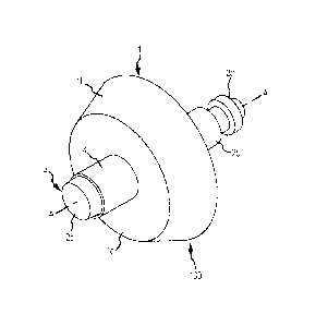
FIG. 1 is an isometric view of an annular optical device according to an
embodiment of the invention.FIG. 2 is an end view of the annular optical
device of FIG. 1.
FIG. 3 is a side view of the annular optical device.
FIG. 4 is a section view AA of the annular optical device along the axis of
revolution A.
FIG. 5 shows the annular optical device according to another embodiment of the
invention.
FIG. 6 is a section view BB of the annular optical device of FIG. 5.
DETAILED DESCRIPTION OF THE INVENTION
FIGS. 1-6 and the following description depict specific examples to teach
those
skilled in the art how to make and use the best mode of the invention. For the
purpose
of teaching inventive principles, some conventional aspects have been
simplified or
omitted. Those skilled in the art will appreciate variations from these
examples that fall
within the scope of the invention. Those skilled in the art will appreciate
that the
features described below can be combined in various ways to form multiple
variations
of the invention. As a result, the invention is not limited to the specific
examples
described below, but only by the claims and their equivalents.
WO 2012/018717 CA 02807630
2013-02-066
PCT/US2011/046105
FIG. 1 is an isometric view of an annular optical device 100 according to an
embodiment of the invention. The annular optical device 100 comprises an
annular
meso-optic 1 and a secondary optical structure 2 that are substantially
centered about an
axis of revolution A. The annular meso-optic 1 includes an annulus 11 that
passes
through the annular meso-optic 1 and is also substantially centered on the
axis of
revolution A (see FIG. 4). The secondary optical structure 2 resides in the
annulus 11
and as a result the secondary optical structure 2 is substantially coaxial to
the annular
meso-optic 1. The secondary optical structure 2 may be positioned within the
annulus
11 so that the secondary optical structure 2 extends at least partially
through the annular
meso-optic 1 in some embodiments. The secondary optical structure 2 may be
positioned to extend fully through the annulus 11 and the annular meso-optic 1
in some
embodiments.
The annular optical device 100 can comprise a component of an optical
instrument. The annular optical device 100 can comprise a component of any
device
that employs scattered, reflected, refracted, redirected, or transmitted light
(or other
visible or invisible electromagnetic radiation).
The annular optical device 100 can comprise a component of any device that
uses light to detect, measure, and/or characterize foreign matter, such as
particulates, in
a fluid. For example, the annular optical device 100 can comprise a component
of a
device used to detect and/or quantify particulates in water. However, the
fluid can
comprise any manner of gases or liquids and can comprise various combinations
of
gases, liquids, and/or solids. The annular optical device 100 can comprise a
component
of a turbidimeter or nephelometer in some embodiments.
The annular optical device 100 can receive light (or other radiation) directed
along the axis of revolution A, into the secondary optical structure 2,
wherein the
annular optical device 100 captures only light that is substantially radially
scattered
within the secondary optical structure 2. The annular optical device 100 re-
directs the
scattered light back out, substantially parallel to the axis of revolution A
and
substantially opposite in direction to the impinging radiation. The annular
optical
device 100 therefore re-directs the radiation as a planar wave front. The
annular meso-
optic 1 of the embodiments herein comprises an axicon. Axicons are optical
elements
that are useful in converging optical radiation propagating as a planar wave
front into a
WO 2012/018717 CA 02807630 2013-
02-067 PCT/US2011/046105
linear foci, or conversely, collimating a radially divergent linear segment of
optical
radiation to a planar wave front. Specifically, an annular axicon performs the
convergence or collimation about an axis of revolution wherein the axicon does
not
occupy the space along the line of focus. Annular axicons are particularly
useful
wherein the line of focus or line of radial divergence is substantially
perpendicular to the
planar wave front.
The secondary optical structure 2 and the annular meso-optic 1 are
separated by a media 12. Media 12 includes a media refractive index that is
lower than a secondary optical structure refractive index.
The secondary optical structure 2 comprises a container including an open end
2a, a wall 2b, and a closed end 2c in some embodiments. In some embodiments,
the
secondary optical structure 2 includes a radiation-transmittable closed end 2c
that is
configured to substantially admit impinging electromagnetic radiation. In some
embodiments, the secondary optical structure 2 includes at least one radiation-
transmittable region in the wall 2b and about and/or along the line of focus 7
of the
annular meso-optic 1, with the at least one radiation-transmittable region
being
configured to substantially pass impinging electromagnetic radiation.
Alternatively, the
entire secondary optical structure 2 can be substantially transmittable to
radiation. The
radiation can travel out of the secondary optical structure 2 through the open
end 2a.
The secondary optical structure 2 can hold a specimen 3 to be tested,
measured,
or otherwise quantified. It should be understood that the specimen 3 may be
statically
held within the secondary optical structure 2 or may be circulated within or
circulated
through the secondary optical structure 2.
The secondary optical structure 2 is configured to hold a specimen to be
radiated by impinging electromagnetic radiation directed into the secondary
optical structure 2 substantially along the axis of revolution A. Radiation
may be
directed into the secondary optical structure 2, such as a beam of light 5,
for
example. The radiation may mainly pass through the specimen 3 held in the
secondary optical structure 2. However, at least some of the radiation may be
scattered. The radiation may be scattered by the specimen 3 (or scattered by
components of or materials of interest within the specimen 3) as the radiation
CA 02807630 2013-02-06
WO 2012/018717 8 PCT/US2011/046105
transits the secondary optical structure 2. The radiation may be scattered at
different angles.
The specimen 3 can comprise a gas, a liquid, or mixtures of gas, liquid,
and/or
solids. The specimen 3 may include particles of gas, liquid, or solids that
are desired to
be detected and/or quantified. The specimen 3 can include suspended particles
or
various mixtures, suspensions, or immiscible materials.
Placement of the secondary optical structure 2 within the annulus of the
annular
axicon/meso-optic 1 creates an angular propagation limitation that controls
the
propagation of radiation into the annular optical device 100. Radiation that
exceeds a
condition for Total Internal Reflection (TIR) is allowed to pass through the
secondary
optical structure 2 and propagate into the annular axicon. This is shown by
the ray 5f in
FIG. 4. However, radiation that is reflected due to TIR propagates only within
the
secondary optical structure 2; i.e., radiation within the secondary optical
structure 2 is
only allowed to exit dependent upon the angle of incidence of the radiation to
the optical
surface of the secondary optical structure 2.
The secondary optical structure 2 is formed of a material such that radiation
impinging on the walls of the secondary optical structure 2 at a relatively
low angle will
be internally reflected, refracted, or otherwise re-directed. This is
illustrated by rays Sc
and 5d of FIG. 4. If the angle of incidence is less than a predetermined
incidence
threshold, then the scattered radiation is internally re-directed by the
secondary optical
structure 2 and cannot pass into the annular meso-optic 1.
The secondary optical structure 2 is positioned within the annulus 11 such
that a
line of focus 7 of the annular meso-optic 1 is located within the secondary
optical
structure 2, and therefore is located within the specimen 3 contained in the
secondary
optical structure 2. An optical beam 5 (or other beam of suitable
electromagnetic
radiation) may be projected along the axis of revolution A of the annular meso-
optic 1,
substantially along the line of focus 7. The measurement volume is defined by
the
chord length of the line of focus 7 and by the cross-sectional area of the
optical beam S.
As a consequence, radiation scattered by the specimen 3 in the region of the
line of
focus 7 may leave the secondary optical structure 2 and enter the annular meso-
optic 1
(see the ray 5f). The scattered radiation received in the annular meso-optic 1
is
substantially radially divergent from a line of focus 7 of the annular meso-
optic 1,
CA 02807630 2013-02-06
WO 2012/018717 9 PCT/US2011/046105
regardless of an angular separation of the impinging electromagnetic radiation
from the
axis of revolution A. However, the secondary optical structure 2 restricts the
scattered
radiation and does not allow all scattered radiation to enter the annular meso-
optic 1.
Scattered radiation from within the secondary optical structure 2 and
within the annulus 11 of the annular meso-optic 1 is allowed into the annular
meso-optic 1 by the secondary optical structure 2 if an angle of incidence of
scattered radiation exceeds a predetermined incidence threshold. The annular
meso-optic 1 re-directs the scattered radiation to comprise re-directed
radiation
that is substantially parallel to the axis of revolution A and substantially
opposite
in direction to the impinging electromagnetic radiation. The annular meso-
optic
may be preferentially positioned so as to re-direct the scattered radiation
substantially parallel to the axis of revolution A and substantially in the
same
direction to the impinging electromagnetic radiation.
Therefore, scattered radiation that impinges on the wall of the secondary
optical
structure 2 at a relatively high angle, i.e., substantially radially, will not
be internally re-
directed and will exit the secondary optical structure 2. Consequently, the
scattered
radiation must be scattered substantially radially and substantially
perpendicularly, i.e.,
at a high angle from the direction of the impinging electromagnetic radiation.
Further, if
the scattered radiation is within the annulus 11 of the annular meso-optic 1,
then the
scattered radiation will be re-directed by the annular meso-optic 1. In some
embodiments, the scattered radiation must be scattered from within a span
denoted by
the line of focus 7. The re-directed radiation exits from the planar annular
optical
surface ld of the annular meso-optic 1. As a result, the re-directed radiation
will be
directed substantially parallel to the axis of revolution A. The re-directed
radiation may
be substantially opposite in direction to the original, entering radiation.
The re-directed
radiation may comprise a substantially planar wave front.
Radially scattered radiation outside of either the annulus 11 or the line of
focus 7
will not enter the annular meso-optic 1. Radially scattered radiation outside
of either the
annulus 11 or the line of focus 7 will not be re-directed by the annular meso-
optic 1. If
the angle of incidence of the scattered radiation is less than the
predetermined incidence
threshold, then the scattered radiation is internally re-directed by the
secondary optical
structure 2 and cannot pass into the annular meso-optic.
CA 02807630 2013-02-06
WO 2012/018717 10 PCT/US2011/046105
Similarly, even if the angle of incidence of the scattered radiation exceeds
the
predetermined incidence threshold, but the scattered radiation is scattered by
the
specimen in the region before the annular meso-optic 1, such as a region
within the
radiation-blocking structure 4, then the scattered radiation may still be
prevented from
leaving the secondary optical structure 2. Ray 5g propagates beyond the
annular optical
arrangement through secondary optical structure 2 and does not contribute to
the
measureable optical signal of interest. Ray 5g does not generate optical noise
and ray
5g is considered to be loss.
The annular optical device 100 can further include a radiation-blocking
structure
4 positioned over or incorporated into at least a portion of the secondary
optical
structure 2, as shown, wherein the radiation-blocking structure 4 blocks
radiation
scattered before encountering the annular meso-optic 1 and therefore prevents
such
scattered radiation from leaving the secondary optical structure 2. The
radiation-
blocking structure 4 can be formed of any appropriate radiation-absorbing
material. The
radiation-blocking structure 4 can be formed of any appropriate radiation-
reflecting
material. The radiation-blocking structure 4 can be formed of any appropriate
radiation-
impenetrable material.
The radiation-blocking structure 4 can be formed so as to fit over at least a
portion of the secondary optical structure 2, as shown. The radiation-blocking
structure
4 in some embodiments can extend at least partially out from the planar
annular optical
surface ld of the annular meso-optic 1. As a result, radiation that is
scattered
substantially radially, but before the annulus 11, is blocked from leaving the
secondary
optical structure 2. As a result, this scattered radiation is therefore
blocked from
entering the planar annular optical surface ld of the annular meso-optic 1.
The
radiation-blocking structure 4, comprising a radiation absorbing media, is
located
beyond the foci of the annular meso-optic 1.
In addition, the radiation-blocking structure 4 may provide a locating or
positioning function. The radiation-blocking structure 4 may substantially
center the
secondary optical structure 2 within the annulus 11 of the annular meso-optic
1. The
radiation-blocking structure 4 may create a desired size and uniformity of
media 12
between the annular meso-optic 1 and the secondary optical structure 2.
CA 02807630 2013-02-06
WO 2012/018717 11 PCT/US2011/046105
FIG. 2 is an end view of the annular optical device 100 of FIG. 1. From this
view, it can be seen that the annular meso-optic 1, the secondary optical
structure 2, and
the radiation-blocking structure 4 may be substantially coaxial. In some
embodiments,
the radiation-blocking structure 4 positions the secondary optical structure 2
substantially coaxially within the annulus 11 of the annular meso-optic 1. The
radiation-blocking structure 4 prevents the outside surface of the secondary
optical
structure 2 from direct contact with the annular meso-optic 1 by centering the
structure
within the annulus of the annular meso-optic.
FIG. 3 is a side view of the annular optical device 100. In this figure, an
optical
beam 5 (or other radiation) is shown entering the closed end 2c of the
secondary optical
structure 2. In this embodiment, the secondary optical structure 2 extends
from either
side of the annular meso-optic 1, but it should be understood that the annular
optical
device 100 may be formed in other configurations and with other dimensions.
The
radiation-blocking structure 4 is located on the secondary optical structure 2
on the side
before the annular meso-optic 1, i.e., between the source of the optical beam
5 and the
annular meso-optic 1.
FIG. 4 is a section view AA of the annular optical device 100 along the axis
of
revolution A. The substantially hollow shape of the secondary optical
structure 2 is
shown in this section view. The solid shape of the annular meso-optic 1 and
the annulus
11 therein are shown in this section view. The substantially pentagonal cross-
sectional
shape of the annular meso-optic 1 of this embodiment is shown in this section
view.
It can be seen that media 12 exists between the annular meso-optic 1 and the
secondary optical structure 2, specifically outside the wall 2b of the
secondary optical
structure 2. Media 12 can comprise a media of air in some embodiments. Media
12,
when comprised of air, will have a media refractive index that is lower than
the
refractive index of wall 2b of secondary optical structure 2 (i.e., the
secondary optical
structure refractive index). However, it should be understood that media 12
may be
comprised of any suitable material that possesses an index of refraction lower
than the
wall 2b of the secondary optical structure 2. As a result of the lower index
of refraction
of media 12, a boundary exists between the wall 2b of the secondary optical
structure 2
and the media 12 which will cause scattered radiation to be refracted,
reflected, or
otherwise internally re-directed by the secondary optical structure 2. If the
scattered
CA 02807630 2013-02-06
WO 2012/018717 12 PCT/US2011/046105
radiation has an angle of incidence less than a predetermined incidence
threshold, then
the scattered radiation will be re-directed and remain within the secondary
optical
structure 2. If the scattered radiation encounters the boundary with an angle
of
incidence greater than the predetermined incidence threshold, then the
scattered
radiation will not be re-directed and will exit the secondary optical
structure 2 through
wall 2b. Such high angle of incidence scattered radiation will be
substantially radial in
direction with respect to the secondary optical structure 2 and the annular
meso-optic 1.
The secondary optical structure 2 can be formed of a suitable material or
materials. The secondary optical structure 2 may be entirely transmittable to
impinging
radiation or may include windows or regions that are transmittable or semi-
transmittable
to radiation within an otherwise radiation-absorbing structure. The secondary
optical
structure 2 may include at least one radiation-transmittable region about the
line of focus
7 of the annular meso-optic 1. The secondary optical structure 2 may include a
radiation-transmittable closed end 2c that is configured to admit impinging
electromagnetic radiation. Radiation-transmittable regions may be of different
material,
of different refractive index, or of different optical opacity. The secondary
optical
structure 2 is shown as comprising a substantially cylindrical container.
However, the
secondary optical structure 2 can be formed of other shapes, as desired.
The annular meso-optic 1 and the secondary optical structure 2 may comprise a
portion of an instrument that quantifies particles in a specimen 3 by
quantifying the
scattering of impinging radiation. In some embodiments, the impinging
radiation
comprises visible or non-visible light. However, electromagnetic radiation of
other
wavelengths may also be employed.
The annular optical arrangement 100 provides utility in converging radiation
from a substantially planar wave to a line of focus. Conversely, the annular
optical
arrangement 100 is capable of collimating a radially divergent linear segment
of
radiation to a substantially planar wave while advantageously restricting the
amount of
radiation not associated with the primary ray path of the optical arrangement
from
propagating out of the annular optical arrangement 100.
The annular meso-optic 1 of the embodiment shown comprises a solid annular
meso-optic 1. The meso-optic is preferentially a solid of revolution about the
axis of
revolution A. The cross-sectional shape is preferentially that of pentagon
which forms a
CA 02807630 2013-02-06
WO 2012/018717 13 PCT/US2011/046105
cylindrical optical surface la parallel to the axis of revolution and a planar
annular
optical surface ld that is substantially perpendicular to the axis of
revolution. An inner
annulus of the planar annular optical surface ld is coincident with the
cylindrical optical
surface la. Optical surfaces lb and lc are substantially conical with respect
to the axis
of revolution A and are convergent to a circular intersection at a distance
radial to the
axis of revolution. The conical optical surfaces lb and lc are preferentially
coated to
reflect radiation impingent upon the internal optical surfaces. In addition,
the conical
optical surface lb is coincident to the outer annulus of the planar annular
optical surface
ld and the conical optical surface lc is coincident to the end of the
cylindrical optical
surface la opposite the planar annular optical surface ld. Non-optical conical
surface
le terminates the convergence of conical optical surfaces lb and lc at a chord
length
along the axis of revolution not less than the length of the cylindrical
optical surface la
so as to reduce the cost of fabrication and fragility of the meso-optic
element without
vignette of the annular optical arrangement. The non-optical conical surface
le is
preferentially inclined about 45 degrees to the axis of revolution. The
conical optical
surfaces lb and lc are inclined relative to the axis of revolution so as to
reflect or
redirect radiation that is substantially perpendicularly radially divergent
from the line of
focus 7 to be substantially parallel to the line of focus 7. Conversely, the
annular meso-
optic 1 can redirect radiation that is traveling substantially parallel to the
line of focus 7
to be substantially radially impinging on the line of focus 7 in the region of
the
cylindrical optical surface la.
An annular meso-optic as described possessing pentagonal cross-sectional
annular volume of revolution converges planar waves of electromagnetic
radiation to
line of focus 7 substantially perpendicular to planar wave propagation or
collimates
optical radiation emitted radially divergent from line of focus 7
substantially
perpendicular from the radial emission regardless of modest error in alignment
of the
annular pentagonal meso-optic axis of revolution to line of focus 7; such as a
modest
error in alignment of several degrees, for example.
It should be noted that annular meso-optic 1 need not be solid construction
nor of
pentagonal cross-sectional shape. Indeed, other conic surface(s) comprised of
first-
surface reflecting, refracting or diffractive surfaces can be used in the
construction of an
CA 02807630 2013-02-06
WO 2012/018717 14 PCT/US2011/046105
annular meso-optic in which the line of focus 7 is substantially coincident to
the axis of
revolution of the meso-optic.
In addition to the shown components and structures, any manner of additional
lenses, components, and/or surfaces may be included in order to direct,
collimate,
disperse, condense, focus, magnify, and/or de-magnify the radiation.
Additional
components may be located before or after the annular optical device 100. For
example,
the annular optical device 100 may include a light or radiation source
adjacent to and
configured to direct radiation into the secondary optical structure 2.
Further, a radiation
detector may be positioned adjacent to the planar annular optical surface ld
of the
annular meso-optic 1 in order to receive and quantify the radiation re-
directed by the
annular meso-optic 1 and exiting from the planar annular optical surface ld.
It is obvious to those skilled in the art of optics, physics or
electromagnetic
theory that planar or spherical propagating waves of optical radiation may be
manipulated by absorptive, refractive, diffractive and reflective elements
alone or by
incorporation with the annular optical device in order to collimate, magnify,
de-
magnify, disperse, condense, or bring to focus said radiation.
The solid annular meso-optic substrate material of the preferred embodiment
may be that of any material transmittable to the radiation of interest. For
example, in
the visible electromagnetic spectrum, the impinging radiation may comprise
electromagnetic radiation between approximately 380 nanometer (nm) to 780nm,
i.e.,
visible light as defined by the Commission internationale de l'eclairage
(CIE). The
substrate material may be that of Schott Glass N-BAK4, N-BK7, PMMA, or any
other
optically transmittable material. Further, the reflective coating on the
conical optical
surfaces lb and lc may be that of gold, silver, aluminum, or any other
material
reflective in the visible spectrum. In addition, the non-optical conical
surface le may be
coated with a light absorptive material such as black paint. The optical
surfaces la and
ld may be uncoated or may be coated to reduce reflection loss at the
wavelength(s) of
interest. For applications in the visible wavelength range, an anti-reflective
coating(s)
may be that of an about quarter-wavelength thickness of magnesium fluoride
(MgF2)
applied to the transmittable optical surfaces la and ld.
In one example, given an optical beam 5 of wavelength 0.5875618 micrometer
(um) (i.e., the Fraunhofer 'cl' helium emission wavelength) propagating in a
surrounding
WO 2012/018717 CA 02807630
2013-02-0615
PCT/US2011/046105
media, like that of air, of refractive index 1.0000 along the line of focus 7
in a direction
so as to enter the planar surface of the glass vial of refractive index 1.5168
into a
specimen of refractive index 1.3330 into outside surfaces 2b of the vial also
residing in
the surrounding media. By Snell's Law of refraction, any redirection of
optical beam 5
due to scatter or other optical phenomenon results in TIR if the angle of
incidence to the
inside wall 2a of the vial is greater than or equal to about 48.6 degrees, as
measured
from the normal or perpendicular to the axis of revolution of the cylindrical
surface, as
in rays Sc and 5d.
FIG. 5 shows the annular optical device 100 according to another embodiment of
the invention. In this embodiment, the annular meso-optic 9 comprises a
substantially
triangular cross section of rotation, specifically a solid-of-revolution of a
right angle
triangle is shown. The triangular annular meso-optic 9 of this embodiment
advantageously has one less optical surface to fabricate, features a shorter
ray path, and
requires less material. Along the axis of revolution of the annulus of the
annular meso-
optic 9 is the secondary optical structure 2. The secondary optical structure
2 and
specimen 3 are coaxial to the triangular annular meso-optic 9. The previous
discussion
of the propagation of the radiation beam 5 and the rays 5a, 5b, Sc, 5d, 5e, 5f
and 5g is
likewise applicable to this embodiment.
FIG. 6 is a cross-section view BB of the annular optical device 100 of FIG. S.
In
the figure, a conical optical surface 9b of the triangular annular meso-optic
9 is inclined
relative to the axis of revolution A so as to reflect any radiation that is
substantially
perpendicularly radially divergent from the line of focus 7. The conical
optical surface
9b redirects the radiation in a direction substantially parallel to the line
of focus 7. The
inner annulus of a planar annular optical surface 9c and a cylindrical optical
surface 9a
are coincident at one end of the cylindrical optical surface 9a. The conical
optical
surface 9b is coincident to an outer annulus of the planar annular optical
surface 9c and
is coincident to the cylindrical optical surface 9a at the end of cylindrical
optical surface
9a that is opposite to the planar annular optical surface 9c. As in other
embodiments,
the conical optical surface 9b may be coated to reflect impinging radiation.
The optical
surfaces 9a and 9c may be discretionarily uncoated to reduce cost or coated to
reduce
reflection loss at the wavelength(s) of interest.
CA 02807630 2013-02-06
WO 2012/018717 16 PCT/US2011/046105
The disclosed annular optical device is not limited to the examples presented
herein. Annular meso-optics comprising one or more conical optical surfaces
may be
used. Annular meso-optics with internally reflecting surface(s) or externally
reflecting
surface(s) may be used. It is further understood that the annular optical
device may be
formed by approximation of the conic optical surfaces using multiple radially
segmented
planar surfaces. In addition, variation in the cross-sectional curvature(s) of
the surfaces
of revolution may also be practiced by modification of one or more of the
disclosed
optical surfaces to optical surfaces that are substantially spherical,
ellipsoidal, parabolic,
or hyperbolic.
The annular optical device 100 may find use in the fields of, for example,
fluorometry, flow cytometry, illuminators, laser optics, electromagnetic
concentrators,
flow metrology, nephelometry, and particle analysis. However, this listing is
not
exhaustive. It should be understood that other uses are contemplated and are
within the
scope of the description and claims.
The detailed descriptions of the above embodiments are not exhaustive
descriptions of all embodiments contemplated by the inventors to be within the
scope of
the invention. Indeed, persons skilled in the art will recognize that certain
elements of
the above-described embodiments may variously be combined or eliminated to
create
further embodiments, and such further embodiments fall within the scope and
teachings
of the invention. It will also be apparent to those of ordinary skill in the
art that the
above-described embodiments may be combined in whole or in part to create
additional
embodiments within the scope and teachings of the invention. Accordingly, the
scope
of the invention should be determined from the following claims.