Note: Descriptions are shown in the official language in which they were submitted.
PERFORATED SHRINK WRAP SLEEVES AND CONTAINERS
CROSS-REFERENCE TO RELATED APPLICATION
[0001] This application claims the benefit of U.S. Appl. No. 61/374,027, filed
August
16, 2010.
FIELD
[0002] The present products and methods relate to packaging, and in particular
to
easy open containers having a perforated shrink wrap sleeve.
BACKGROUND
[0003] Sealing product containers, labeling container contents and providing
evidence
that a container has not been opened are known using heat-shrinkable films
('shrink
wrap'). Applying such films are described in U.S. Patent No. 6,296,129 to
Kawasaki and
U.S. Patent No. 5,605,230 to Marino et al. Shrink wrap applications can be
economically applied to a variety of containers for a variety of products,
such as food or
pharmaceutical applications.
[0004] Despite the advantages of heat shrink films, shrink wrap packaging can
sometimes be difficult for irregularly shaped containers. In such cases,
shrink wrap can
be difficult to apply, difficult to remove, and difficult to provide printed
matter without
noticeable distortion.
1
CA 2807777 2017-09-07
CA 02807777 2013-02-07
WO 2012/024218 PCT/US2011/047750
SUMMARY
[0005] Accordingly, provided herein are embodiments for perforated shrink wrap
sleeves and containers with perforated shrink wrapped sleeves configured to
provide
easy partial removal, evidence of tamper, and product labeling - even with
irregularly
shaped and non-symmetrical containers.
[0006] A preferred embodiment provides a container having a container body
that can
have a circumference/perimeter variation along a vertical axis, a bottom
surface, and a
container opening having a top surface; an axially oriented shrink wrap sleeve
covering
a portion of the body of the container having a circumference variation and
the container
opening, a top edge of the shrink wrap sleeve allowing the top surface to
remain
exposed, and bottom edge of the shrink wrap sleeve allowing the bottom surface
to
remain exposed: the shrink wrap sleeve having a pair of generally vertical
perforations
descending from the shrink wrap top edge towards a circumferential perforation
ring
oriented below the container opening. In some embodiments, the axially
oriented shrink
wrap sleeve covering a portion of the container body circumference variation
has a
greater circumference as compared to adjacent portions of the circumference
variation
at at least one point between the shrink wrap top (or alternately shrink wrap
circumferential perforation ring) and bottom edges.
[0007] In other embodiments the axially oriented shrink wrap sleeve covering a
portion of the container body circumference variation can have a smaller
circumference
as compared to adjacent portions of the circumference variation at at least
one point
between the shrink wrap horizontal perforations and bottom edges.
Circumference
CA 02807777 2013-02-07
WO 2012/024218 PCT/US2011/047750
variation can be in the range of about 5 percent to about 200 percent, and
preferably
about 100 percent.
[0008] Generally vertical perforations descending from the shrink wrap top
edge can
converge progressively closer together as they approach the circumferential
ring. The
vertical perforations descending from the shrink wrap top edge can terminate
at the
circumferential ring or alternately about two perforations above the
circumferential ring.
Such a distance corresponds to the length between two perforations or more of
the
generally vertical perforations.
[0009] In other embodiments, the shrink wrap vertical perforations descending
from
the shrink wrap top edge can begin with an initial perforation cut, followed
by
proportionally smaller perforation cuts, configured so that when the shrink
wrap is
applied to the container body, the larger cut forms as 'V' shape at a top of
each vertical
perforation to define a tab between the vertical perforations.
[0010] The container body can generally have a planar front and rear surface,
and a
seal of the shrink wrap is vertically oriented along an edge of the rear
surface.
[0011] In a specific embodiment, the container can have a container body
having a
vertical axis, a bottom surface, and a container opening having a top surface;
a
vertically oriented shrink wrap sleeve covering a portion of the container
body and the
container opening, a top edge of the shrink wrap sleeve allowing the top
surface to
remain exposed, and bottom edge of the shrink wrap sleeve allowing the bottom
surface
to remain exposed; the shrink wrap sleeve having a pair of generally vertical
perforations descending from the shrink wrap sleeve top edge towards a
circumferential
perforation ring oriented below the container opening.
3
CA 02807777 2013-02-07
WO 2012/024218 PCT/US2011/047750
[0012] In another specific embodiment, the container can have a container body
having a circumference variation along a vertical axis, a bottom surface, and
a container
opening having a top surface: a vertically oriented shrink wrap sleeve
covering a portion
of the circumference variation of the container body and the container
opening, a top
edge of the shrink wrap sleeve allowing the top surface to remain exposed, and
bottom
edge of the shrink wrap sleeve allowing the bottom surface remain exposed: the
shrink
wrap sleeve having a pair of generally vertical perforations descending from a
distance
below the shrink wrap sleeve top edge towards a circumferential perforation
ring
oriented below the container opening.
[0013] Embodiments of a shrink wrap sleeve suitable for use for covering a
portion of
a container along a vertical axis having a circumference variation can have a
top edge
and bottom edge: the shrink wrap sleeve having a pair of generally vertical
perforations
descending from the shrink wrap sleeve top edge towards a circumferential
perforation
ring. Optional features of the present embodiments can include printed indicia
and
adhesive to bond the container to the shrink wrap sleeve. The shrink wrap
sleeve of
claim 14 can be a polyolefin, a polymer such as polyethylene terephthalate
(PET), a
copolymerized polyethylene terephthalate (PETG), polyethylene terephthalate
glycol
(PETG I.V), polyvinyl chloride (PVC), polypropylene (PP), polyethylene (PE),
and
combinations thereof. Preferably the shrink wrap sleeve is a PETG, and even a
PETG
LV. The shrink wrap film can have a gauge of between about 40 to 55 microns,
and
preferably about 45 microns. The shrink wrap sleeve can have a shrinkage rate
of
about 75 percent to about 85 percent, and a shrinkage ratio of about 2:1.
4
[0013a] In an aspect, there is provided a container, comprising: a container
body
having a circumference/perimeter variation along a vertical axis, a bottom
surface, and a
container opening including a flip top cap having a top surface; an axially
oriented shrink
wrap sleeve covering a portion of the body of the container having a
circumference
variation and a portion of the container opening, a top edge of the shrink
wrap sleeve
allowing the top surface to remain exposed, and a bottom edge of the shrink
wrap sleeve
allowing the bottom surface to remain exposed; the shrink wrap sleeve having a
pair of
generally vertical perforations descending from the shrink wrap top edge
towards a
circumferential perforation ring oriented below the container opening, the
shrink wrap
sleeve above the circumferential perforation ring being an upper band that
covers a
seam of the flip top cap and that can be removed to expose the flip top cap
and allow the
flip top cap to be opened for product removal; wherein the shrink wrap sleeve
covering a
portion of the container body circumference variation has one of a smaller or
larger
circumference at at least one point between the circumferential perforation
ring and the
bottom edge as compared to adjacent portions of the circumference variation in
order to
prevent the shrink wrap sleeve from slipping off the container after removal
of the portion
thereof extending between the circumferential perforation ring and the top
edge.
[0014] Other features will become more apparent to persons having ordinary
skill in
the art to which the package pertains and from the following description and
claims.
BRIEF DESCRIPTION OF THE DRAWINGS
[0015] The foregoing features, as well as other features, will become apparent
with
reference to the description and Figures below, in which like numerals
represent like
elements, and in which:
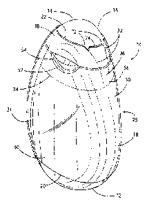
[0016] FIG. 1 is a front perspective view of one embodiment of an exemplary
container having a perforated shrink wrap sleeve;
CA 2807777 2017-09-07
[0017] FIG. 2 is a front perspective view of one embodiment of an exemplary
container having a perforated shrink wrap sleeve with a first perforation
peeled away;
[0019] FIG. 3 is a front perspective view of one embodiment of an exemplary
container having a perforated shrink wrap sleeve with a first perforation
removed and a
second perforation peeled partially away;
[0019] FIG. 4 is a front perspective view of one embodiment of an exemplary
container having a perforated shrink wrap sleeve with a first and second
perforation
peeled away;
[0020] FIG. 5 is a rear perspective view of one embodiment of an exemplary
container having a perforated shrink wrap sleeve;
[0021] FIG. 6 illustrates one embodiment of an exemplary perforated shrink
wrap
sleeve in a front planar view (6a) and as a side view placed on a container
(6b);
[0022] FIG. 7 illustrates a second embodiment of an exemplary perforated
shrink
wrap sleeve in a front planar view (7a) and as a side view placed on a
container (7b);
5a
CA 2807777 2017-09-07
CA 02807777 2013-02-07
WO 2012/024218 PCT/US2011/047750
[0023] FIG. 8 illustrates a third embodiment of an exemplary perforated shrink
wrap
sleeve in a front planar view (8a) and as a side view placed on a container
(8b);
[0024] FIG. 9 illustrates a fourth embodiment of an exemplary perforated
shrink wrap
sleeve in a front planar view (9a) and as a side view placed on a container
(9b);
[0025] FIG. 10 illustrates a fifth embodiment of an exemplary perforated
shrink wrap
sleeve in a front planar view (10a) and as a side view placed on a container
(10b);
[0026] FIG. 11 illustrates one embodiment of an exemplary perforated shrink
wrap
sleeve in a rear planar view;
[0027] FIG, 12 illustrates a blank of one embodiment of a shrink wrap sleeve
for a
container; and
[0028] FIG. 13 is a front planar view of second embodiment of an exemplary
container
having a perforated shrink wrap sleeve.
DETAILED DESCRIPTION OF PREFERRED EMBODIMENTS
[0029] Provided herein are embodiments for perforated shrink wrap sleeves and
containers with perforated shrink wrapped sleeves configured to provide easy
partial
removal, evidence of tamper, and product labeling - even with irregularly
shaped and
non-symmetrical containers,
[0030] Generally, the present embodiments illustrate a cost efficient and easy
open
feature for consumers to obtain full product access. As described, the present
embodiments can provide printed surfaces to provide graphics and other types
of
printed information on a shrink wrapable film that can be transparent,
translucent,
opaque, or variations/combinations thereof. Metallic inks can also be provided
to
6
CA 02807777 2013-02-07
WO 2012/024218 PCT/US2011/047750
provide a silver or metallic hue. To accommodate container shape
irregularities, a
maximum to minimum shrinkage ratio should be at least 2:1. It is noted that
various
product container sizes are possible so long as the shrink wrap can be
maintained
thereon even after a partial band of film has been removed. Preferably, the
shrink wrap
film is applied as a sleeve. When a container bottom is present, it is
preferably not
encapsulated by the shrink wrap. On top tapered containers, the sleeve should
terminate at a height on the container so that no 'puckering would occur. For
example,
for the container embodiments illustrated in FIGs. 1 and 13, a sleeve is shown
that is
proportioned to reduce any evidence of a 'pucker' near the top and is not
present on the
bottom to allow the container to stand on its own.
(0031] The perforations of the present embodiments can permit removal of
shrink
wrap above the shoulder area, which allows access to a container opening, such
as a
flip top cap. The shrink wrap perforations provide a tamper evident feature in
that once
the perforations have been breached (ruptured) and/or a partial band of film
material
has been removed, it is visually obvious that the container has been opened.
There are
several perforation patterns described within the present embodiments, though
it is
noted that several other variations are possible. Nevertheless, the general
features of
the perforation patterns can provide two separate perforation types. A first
pattern can
be a pair of perforations axially oriented to the sleeve to form a tab; and a
second
pattern can be a generally circumferential ring pattern perpendicular to the
axially
oriented perforations to define an upper band for removal, The axial pair of
perforations
can terminate at or near (e.g,, 1-5 mm or 1-3 perforations) above the
circumferential
ring. The patterns can be configured to remove the upper band of material in
one
7
CA 02807777 2013-02-07
WO 2012/024218 PCT/US2011/047750
motion or by removing first a vertical tab, and then the remaining portion of
the upper
band. The material for the shrink wrap should be configured to withstand
multiple
container flexing (e.g., at least 50 times). This feature is useful for a
container that
contains products, such as a beverage concentrate, that require the container
to be
squeezed to deliver product.
[0032] Turning now to the Figures, a container having a perforated shrink wrap
sleeve
is generally indicated at 10. As shown, the container 10 can be used to
dispense a
liquid concentrate in a desirable manner. The container 10 can include
desirable
properties, for example, to consistently discharge across a range of squeezed
forces,
generally consistent discharge with the same force without significant
dependence on
the amount of liquid concentrate in the container, a substantially dripless or
leak proof
outlet opening, a jet that minimizes splashing when the liquid concentrate
enters
another liquid, and a jet that maximizes mixing between the liquid concentrate
and the
other liquid. The container 10 utilizes some or all of these properties while
dispensing a
jet of the liquid concentrate into a target container having a target liquid
therein. The
container 10 described herein can dispense a liquid concentrate in such a way
as to
enter the target liquid without substantial splashing or splatter while also
causing
sufficient turbulence or mixing within the target container between the liquid
concentrate
and the target liquid to form a generally homogenous end mixture without the
use of
extraneous utensils or shaking,
[0033] Referring now to FIGs, 1 and 13, exemplary forms of the container 10
are
shown with at least some, and preferably all, of the above properties. The
container
can include a closed, first end 12 and a top, second end 14 having a hinged
flip top cap
CA 02807777 2013-02-07
WO 2012/024218 PCT/US2011/047750
16 secured to a back surface 23 by a hinge 44. The first end 12 and the flip
top cap 16
can be connected by a generally tubular sidewall 18, which can take any
suitable cross
section, including any polygonal shape, any curvilinear shape, or any
combination
thereof, to form a container interior. Preferably, the container 10 can be
sized for any
number of uses and can specifically be in the range of 20 to 200 cc.
[0034] Exemplary shapes of the container 10 are illustrated in FIGs. 1 and 13
in which
the first end 12 acts as a secure base for the container 10 to rest upon. The
sidewall 18
can generally extend upward from the base or first end 12 to the second end
14. In the
form of FIG. 1, the container 10 can have a generally 'egg' shape, where front
and rear
surfaces 21 and 23 respectively are curved to provide an ergonomic container
shape.
In another example in FIG. 13, the sidewalls 18 can include a 'waist' 80 so
that the
container 10 has an 'hourglass' shape on its front planar view.
[0035] Partially covering the container 10, including a seam for the flip top
cap 16 can
be a perforated shrink wrap sleeve 30 having two perforation patterns
including
generally a pair of vertical perforations 32 extending downward toward a
horizontal
(circumferential) perforation ring 34. The shrink wrap sleeve 30 can be a
polyolefin
such as polyethylene terephthalate (PET), a copolymerized polyethylene
terephthalate
(PETG), polyethylene terephthalate glycol (PETG LV ==== such as sold as a film
by
GILBRETH, Croydon, PA, USA), polyvinyl chloride (PVC), polypropylene (PP),
polyethylene (PE), and combinations thereof (or other shrinkable films).
Preferably, the
shrink wrap sleeve 30 is PETG. The gauge of the shrink wrap sleeve 30 can be
about
40 to 55 microns, preferably about 45 microns. Shrinkage of the shrink wrap
sleeve 30
can be at a shrinkage rate of about 75 percent to about 85 percent (preferably
about 76
9
CA 02807777 2013-02-07
WO 2012/024218 PCT/US2011/047750
percent) and have a shrink ratio selected to preferably withstand a shrinkage
ratio of
about 2:1. The shrink wrap sleeve 30 can provide printed surfaces for graphics
and
other types of printed information or indicia on film that can be transparent,
translucent,
opaque, or various combinations thereof. Metallic inks can also be provided to
provide
a silver or metallic hue.
[0036] In the present embodiments, the container 10 preferably has a body
having a
circumference variation along an axis oriented to receive the shrink wrap
sleeve 30,
such as a vertical axis. It is noted that circumference by the present term
can mean a
perimeter variation and can include circles, ellipses and other various
curvilinear or
geometric shaped cross-sections. By way of illustration, container 10 is
configured to
receive a shrink wrap sleeve 30 along a vertical axis. The portion of the
container body
covered by shrink wrap sleeve 30 can have a circumference variation having a
greater
(FIG. 1, 18) or lesser (FIG. 13, 80) circumference at at least one point
between the
shrink wrap horizontal perforation ring 34 and a shrink wrap bottom edge 20 as
compared to adjacent portions of the circumference. Alternately, the portion
of the
container body covered by the shrink wrap sleeve 30 can have a circumference
variation having a greater (FIG. 1, 18) or lesser (FIG. 13, 80) circumference
at at least
one point between the shrink wrap top edge 22 and the shrink wrap bottom edge
20 as
compared to adjacent portions of the circumference. This variation can
preferably
range from about 5 percent to about 200 percent, and most preferably at about
100
percent. Printing on a blank 28 (FIG. 12) for the shrink wrap sleeve 30 can
have its
printing distorted to accommodate circumference variation once the shrink wrap
film has
been applied to the container. For example, for the container 10 of FIG. 1
having a film
CA 02807777 2013-02-07
WO 2012/024218 PCT/US2011/047750
height of about 80 mm and placed as shown in FIG. 1, distortion rates can be
based on
the following distortion percentage TABLE as follows:
TABLE:
Percent distortion Vertical bottle height position Cmrn)
135 62-80
117 50-62
110 15-50
120 0-15
[0037] The axial circumference variation can prevent the shrink wrap seal from
slipping off the container before and/or after an upper band of shrink wrap is
removed to
expose a container opening, such as the illustrated flip top cap 16 and allow
it to be
opened for product removal. Alternately, an adhesive can be applied between
the
container 10 body and an inner surface of the shrink wrap sleeve 30 in various
configurations.
[0038] The perforation patterns for the present embodiments can be varied but
preferentially include a generally circumferential ring of perforations
generally
perpendicular to the vertical perforations 32, Horizontal perforations 34 for
a vertically
oriented shrink wrap sleeve 30, as illustrated, generally define an upper edge
of the
shrink wrap sleeve 30 remaining after the upper band 38 is removed to expose
the
container opening for product removal.
[0039] A second aspect of the shrink wrap sleeve 30 perforations is a pair of
perforations that can run generally perpendicular to the circumferential ring
of
perforations. As illustrated for a vertically oriented shrink wrap sleeve,
generally vertical
11
CA 02807777 2013-02-07
WO 2012/024218 PCT/US2011/047750
perforations 32 can descend from the shrink wrap top edge 22 towards the
horizontal
ring perforation ring 34, which is oriented below access to the flip top cap
16. Access to
flip top cap 16 can be by way of a recession portion 52 under a ledge 54.
Again, many
perforation pattern variations are possible within the scope of the
embodiments. FIGs.
6 ¨ 10 illustrate just a sample of these types of variations. The vertical
perforations 32
can be parallel, converge, or expand as they extend (here, descend) towards
the
circumferential perforation ring 34. The vertical perforations 32 can
terminate at the
horizontal ring 34 or terminate at some point above the horizontal ring 34.
[0040] As illustrated, the vertical perforations preferably converge as they
approach
the horizontal ring 34. FIG. 6a shows a perforation pattern for a shrink wrap
sleeve
ready for placement and heat shrinking onto the container body 10. FIG. 6b
illustrates
the shrink wrap sleeve 30 after it has been applied to the container 10 and
affixed to the
container by heat shrinking or other means known in the art to shrink a film
on a
container. FIGs. 7-10 illustrate similar views for alternate perforation
pattern
embodiments. It is noted that any feature or the various embodiments can be
interchanged within the other embodiments.
[0041] As to FIG. 6, the vertical perforations 32 converge as they approach
and
terminate at the horizontal line 34. Large cuts 66 are added to the top end of
the
vertical perforations 32 to provide a splitting effect, a "V" 72, when applied
to the
container 10_ The pair of "V"s 72 provides a peel tab 74 to allow easy removal
by a
user. It is noted that as a user pulls on the peel tab 74, a vertical tab 36
is generated as
the shrink wrap ruptures between the perforations. It is also noted that any
ruptured
patterns allow a visual inspection of the container to reveal whether the
container has
12
CA 02807777 2013-02-07
WO 2012/024218 PCT/US2011/047750
ever been opened or tampered with after shrink wrapping has been placed on the
container.
[0042] FIG. 7 shows a variation of the position of the large cut 66 below the
top edge
22 of the shrink wrap sleeve 30. In other words, the large cut 66 is placed
below one or
more normal perforation cuts on the top edge of the sleeve 30. In this
instance, the
heat shrinking separates the shrink wrap to form a circular opening to assist
in
developing a vertical tab 36 without forming a distinct peel tab 74.
[0043] FIG. 8 shows a variation of the perforation pattern by terminating the
vertical
perforations 32 before they reach the horizontal ring 34. This can be defined
by not
placing one, two, or three perforations before it reaches horizontal ring 34.
For a
container of about 80 mm in height, this non-perforated area 68 can have a
dimension
70 of about 1 to 5 mm, and preferably about 1 to 2 mm. FIG. 9 illustrates
where only
one of vertical perforations 32 has a non-perforated area 68.
[0044] FIG. 10 illustrates a horizontal cut 78 so that as the vertical tab 36
is removed
(See, e.g., FIG. 2) it separates from the shrink wrap sleeve 30 when it
reaches the
horizontal perforation ring.
[0045] In use, as shown in the sequence of Figures 2-4, a user can pinch the
tab 74
and pull the shrink wrap toward the horizontal ring 34 to form the vertical
tab 36 (FIG.
1). Depending on the perforation pattern, a user can continuously pull the
vertical tab
36 until it approaches the horizontal ring 34, followed by a horizontal pull
(FIG. 2) to
continue the shrink wrap rupture of the horizontal ring perforations until an
upper shrink
wrap band 38 is removed (FIG. 3). Once the band 38 is removed, the lower
shrink wrap
band 40 remains and the product is ready for use.
13
CA 02807777 2013-02-07
WO 2012/024218 PCT/US2011/047750
[0046] The shrink wrap 30 can be formed by a blank 28 from a continuous film
of
PETG as shown in FIG. 12. As shown in FIG. 12, cut lines 50 define the size of
the
sleeve blank 28 as well as fold lines 48, seal area 42, copy limit 56, no live
copy 58, no
legal information 60 (since that portion on the shrink wrap will be removed
prior to use),
front panel print 62, and rear panel print 64. Once a blank has been formed,
the film is
sealed at the seal area 42 and the perforations 32 and 34 are added to form
the shrink
wrap seal that is ready for placement on the container 10. It is noted that
there are
limitless variations that are possible to forming blanks for heat shrinking
onto a
container,
[0047] While preferred embodiments have been described in detail, variations
and
modifications can be effected within the scope of the presented embodiments,
14