Language selection

Search

Patent 2808150 Summary

Third-party information liability

Some of the information on this Web page has been provided by external sources. The Government of Canada is not responsible for the accuracy, reliability or currency of the information supplied by external sources. Users wishing to rely upon this information should consult directly with the source of the information. Content provided by external sources is not subject to official languages, privacy and accessibility requirements.

Claims and Abstract availability

Any discrepancies in the text and image of the Claims and Abstract are due to differing posting times. Text of the Claims and Abstract are posted:

  • At the time the application is open to public inspection;
  • At the time of issue of the patent (grant).
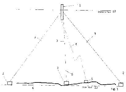
(12) Patent Application: (11) CA 2808150
(54) English Title: OCEANIC COMMUNICATIONS SYSTEM
(54) French Title: SYSTEME DE COMMUNICATIONS OCEANIQUES
Status: Deemed Abandoned and Beyond the Period of Reinstatement - Pending Response to Notice of Disregarded Communication
Bibliographic Data
(51) International Patent Classification (IPC):
  • H04B 13/02 (2006.01)
(72) Inventors :
  • PLENTL, BRETT A. (United States of America)
(73) Owners :
  • BRETT A. PLENTL
(71) Applicants :
  • BRETT A. PLENTL (United States of America)
(74) Agent: MARKS & CLERK
(74) Associate agent:
(45) Issued:
(86) PCT Filing Date: 2010-09-09
(87) Open to Public Inspection: 2011-03-17
Availability of licence: N/A
Dedicated to the Public: N/A
(25) Language of filing: English

Patent Cooperation Treaty (PCT): Yes
(86) PCT Filing Number: PCT/US2010/048198
(87) International Publication Number: US2010048198
(85) National Entry: 2013-02-12

(30) Application Priority Data:
Application No. Country/Territory Date
12/875,645 (United States of America) 2010-09-03
61/240,840 (United States of America) 2009-09-09

Abstracts

English Abstract

A system of buoys (1) is connected by vertical cables (2) to submarine fiber optic communications cable (6) on the ocean floor or in cases where no submarine fiber optic cable is present, the buoys (1) will use satellite communication. The buoys (1) are aligned on the surface of the ocean, underneath heavily traveled oceanic air routes to provide platforms for radios. The satellite or cable connection to the buoys (1) enables high bandwidth communications backhaul from the buoy (1) to the internet or public switched telephone network. The high bandwidth buoys (1) provide a platform to put different radio systems, enabling a substantially uninterrupted radio connection to high altitude aircraft as they transit oceanic airspace.


French Abstract

L'invention porte sur un système de bouées (1) qui est connecté par des câbles verticaux (2) à un câble de communications à fibres optiques sous-marin (6) sur le fond de l'océan ou, dans des cas où aucun câble à fibres optiques sous-marin n'est présent, les bouées (1) utiliseront une communication par satellite. Les bouées (1) sont alignées sur la surface de l'océan, sous des routes aériennes océaniques à fort trafic, de façon à fournir des plateformes pour les radios. La connexion par satellite ou par câble aux bouées (1) permet une retransmission de communications à grande largeur de bande de la bouée (1) vers le réseau téléphonique public ou l'Internet. Les bouées à grande largeur de bande (1) fournissent une plateforme afin de mettre en place différents systèmes de radio, permettant une connexion par radio sensiblement ininterrompue à des avions à haute altitude lorsqu'ils traversent l'espace aérien océanique.

Claims

Note: Claims are shown in the official language in which they were submitted.

CLAIM(S):
1. An array of buoys positioned and retained at selected positions by being
anchored to an
ocean floor, the buoys being positioned at an ocean's surface, the array
substantially traversing
an ocean coextending with a commercial transoceanic flight path, the array
providing a
substantially continuous wireless signal to aircraft traveling along the
commercial transoceanic
flight path such that the buoys provide a substantially continuous
communication system.
2. The array of buoys of claim 1 wherein the buoys have platforms for
positioning
receiver/transmitter devices.
3. The array of buoys of claim 2 wherein the receiver/transmitter devices
comprise radios.
4. The array of buoys of claim 1 wherein fiber optic cables are positioned on
the ocean
floor, and the array of buoys further comprises a plurality of vertically
extending cables,
extending from the buoys to the fiber optic cables.
5. The array of buoys of claim 1 wherein the receiver/transmitter devices are
in
communication with communication satellites.
6. The array of buoys of claim 1 and further comprising at least one
electrical generator
positioned on at least one of the buoys to provide electrical power.
7. The array of buoys of claim 6 and further comprising at least one junction
box or
branching unit positioned below the ocean surface for providing electrical
power below the
ocean surface.
6

8.
The array of buoys of claim 6 and further comprising at least one fiber optic
cable
connector in data communication with either a fiber optic cable on the ocean
floor or in data
communication with a satellite.
9.
The array of buoys of claim 4 and further comprising at least one attachment
point
positioned on at least one of the vertical cables, the attachment point being
positioned below the
ocean's surface, the attachment point providing an electrical connection or a
data communication
connection below the ocean's surface.
7

Description

Note: Descriptions are shown in the official language in which they were submitted.


CA 02808150 2013-02-12
WO 2011/031815 PCT/US2010/048198
OCEANIC COMMUNICATIONS SYSTEM
CROSS-REFERENCE TO RELATED APPLICATION
[0001] The present application is based on and claims the benefit of U.S.
provisional
patent application Serial No. 60/240,840, filed September 9, 2009, the content
of which is
hereby incorporated by reference in its entirety.
BACKGROUND OF THE INVENTION
[0002] The present invention is in the technical field of communications. More
particularly, the present invention is in the technical field of ocean-based
communications.
[0003] Current ocean-based communications systems, such as submarine fiber
optic
cable, do not offer data paths to the surface of the ocean, except at the
cable landing
stations. Aircraft or ships transiting the ocean are dependent on satellite-
based
communications systems, even though the routes they fly or sail often
approximate the
same paths where submarine fiber optic cable is laid on the ocean floor.
BRIEF SUMMARY OF THE INVENTION
[0004] The present invention is a system of buoys, connected by vertical
cables to
submarine fiber optic communications cable on the ocean floor or in cases
where no
submarine fiber optic cable is present, the buoys will use satellite
communication. The
buoys are aligned on the surface of the ocean, underneath heavily traveled
oceanic air
routes to provide platforms for radios. The satellite or cable connection to
the buoys
enable high bandwidth communications backhaul from the buoy to the intern& or
public
switched telephone network. The high bandwidth buoys provide a platform to put
different radio systems, enabling a substantially uninterrupted radio
connection to high
altitude aircraft as they transit oceanic airspace.
BRIEF DESCRIPTION OF THE SEVERAL VIEWS OF THE DRAWING
[0005] Fig. 1 is a side view of one buoy comprising part of the present
invention;
1

WO 2011/031815 CA 02808150 2013-02-12 PCT/US2010/048198
[0006] Fig. 2 is a top view of one buoy comprising part of the present
invention; and
[0007] Fig. 3 is a top system view of several buoys comprising part of the
present
invention.
[0008] Fig. 4 is a diagrammatical view of a system of buoys of this invention
showing
buoy positions along aircraft traffic in the North Atlantic Track System.
DETAILED DESCRIPTION OF THE INVENTION
[0009] Referring now to the invention in more detail, in Fig. land Fig. 2
there is shown a
large buoy or structure 1 floating on the surface of the ocean 10 and attached
to the ocean
floor 12 by a combination of anchors 3 and mooring lines. 2. The buoy or
structure 1 is
also attached to an undersea junction box or branching unit 5 by a dynamic
riser 4. The
undersea junction box 5 is also attached to an undersea fiber optic cable
system 6. When
no fiber optic submarine cable is available, satellite communications will be
used.
[0010] Fig 3 depicts a Top System View of several large buoys or structures 1
moored in
position by anchors 3 and mooring lines 2, and attached by dynamic risers 4 to
the
submarine junction box or branching unit 5 and to a submarine fiber optic
cable system 6.
When no fiber optic submarine cable is available, satellite communications
will be used.
The several large buoys or structures 1 are optimally positioned on the
surface of the
ocean under heavily traveled air routes.
[0011] In more detail, still referring to the invention of Fig. 1 and Fig 2,
the buoy or
structure 1 contains electric generators, fuel, as well as equipment and
wiring required to
deliver wideband intern& connectivity and electricity to voice and data radio
systems.
The large buoy or structure 1, functioning as a floating radio mast, is
seaworthy and tall
enough to provide line of sight connectivity in storm conditions to high
altitude aircraft.
The large buoy or structure 1 is constructed of long life marine grade
materials like steel
or concrete. Other suitable materials that can withstand the rigors of an
ocean salt-water
2

WO 2011/031815 CA 02808150 2013-02-12 PCT/US2010/048198
environment may be used. The buoy or structure 1 may also contain a satellite
communications system.
[0012] Still referring to the invention in Fig. 1 and Fig.2, the mooring lines
3 have
sufficient length and strength to hold the buoy at the designated location on
the surface of
the ocean. The type of anchors 2 may vary based on sea floor composition and
type.
Deadweight anchors or suction pile anchors are two possibilities.
[0013] Still referring to the invention in Fig 1 and Fig 2, the dynamic riser
4 connects the
buoy to the undersea junction box 5. The dynamic riser 4 is a vertical
umbilical cable,
extending through the water column, connecting the floating buoy or structure
1 to the
undersea junction box 5 on the ocean floor 12. The dynamic riser 4 contains
fiber optic
cable, electrical cable, load bearing cable, and connectors spaced along its
length. The
connectors provide electrical power and bandwidth to oceanographic sensors or
to
autonomous underwater vehicles. The undersea junction box 5 contains
electrical power
connectors and fiber optic cable connectors that can provide power and
bandwidth to
undersea oceanographic sensors. When using a transoceanic undersea fiber optic
cable 6
to provide an internet connection to the buoy or floating structure 1,
undersea junction
box 5 provides the interface from the undersea fiber optic cable 6 to the
large buoy or
structure 1. The undersea junction box 5 can be spliced directly into the
undersea fiber
optic cable system 6 or it can be some distance from the undersea fiber optic
cable system
6 and connect to it via an industry standard branching unit on the undersea
fiber optic
cable system 6 with an extension fiber optic cable to the undersea junction
box 5. If
satellite communication is being used to provide an intern& connection (no
undersea
fiber optic cable available), the undersea junction box 5, provides bandwidth
to the
oceanographic sensors via the dynamic riser 4 connection to the satellite
communications
system contained in the buoy.
3

WO 2011/031815 CA 02808150 2013-02-12PCT/US2010/048198
[0014] Referring to the invention in Fig. 3, the buoy or structure 1, is a
single part of a
larger oceanic scale system depicted in Fig. 3. The buoys or structures 1 are
aligned to
overhead commercial air traffic routes or corridors and to a dedicated or
existing
undersea fiber optic cable system 6. When no fiber optic submarine cable is
available,
satellite communications will be used. Spacing between buoys is based on radio
line of
sight to the high altitude commercial air traffic.
[0015] In further detail, still referring to the invention in Fig. 1 and Fig.
2, the buoy or
structure 1 is sufficiently large to be seaworthy and provide enough freeboard
in the
worst sea conditions, such as about 30 feet to 700 feet in length. The mooring
lines 3 are
typically between 5-10 times the water depth in length. For example, the
average water
depth in the North Atlantic is approximately 14,000 feet, so each mooring line
3 would
be between 70,000 and 140,000 feet in length depending on operational
requirements and
weather and sea conditions. Referring to the system of buoys in Fig. 3, the
buoys or
structures 1 are spaced between 150-250 nautical miles apart and are aligned
longitudinally with the commercial air routes overhead. Great circle routes
are the
shortest distance between two points on the surface of the earth. Since
airliners will
normally fly to the left or right of a great circle route based on high
altitude winds, the
buoys or structures 1 will also be placed 150-250 nautical miles apart axially
along the
commercial air route.
[0016] The advantages of the present invention include, without limitation,
the ability to
provide a constant radio connection to high altitude aircraft as they transit
the ocean, as
well as a location to install ocean floor sensors, ocean water column sensors,
and ocean
surface sensors to advance scientific knowledge and improve weather
forecasting.
[0017] Fig. 4 illustrates a system or an array of buoys in the North Atlantic
Track
System. The buoys are located approximately in the center of the circles, the
circle
illustrating the communication range of each respective buoy. The
communication range
4

WO 2011/031815 CA 02808150 2013-02-12 PCT/US2010/048198
overlap of adjacent buoys is shown by the overlap of the circles. The dots
along the
North Atlantic Track System indicate aircraft. The overlap in range of the
buoys
provides a substantially continuous communication system to aircraft flying
overhead.
5

Representative Drawing
A single figure which represents the drawing illustrating the invention.
Administrative Status

2024-08-01:As part of the Next Generation Patents (NGP) transition, the Canadian Patents Database (CPD) now contains a more detailed Event History, which replicates the Event Log of our new back-office solution.

Please note that "Inactive:" events refers to events no longer in use in our new back-office solution.

For a clearer understanding of the status of the application/patent presented on this page, the site Disclaimer , as well as the definitions for Patent , Event History , Maintenance Fee  and Payment History  should be consulted.

Event History

Description Date
Application Not Reinstated by Deadline 2015-09-09
Time Limit for Reversal Expired 2015-09-09
Deemed Abandoned - Failure to Respond to Maintenance Fee Notice 2014-09-09
Inactive: Cover page published 2013-04-17
Inactive: Notice - National entry - No RFE 2013-03-15
Application Received - PCT 2013-03-15
Inactive: First IPC assigned 2013-03-15
Inactive: IPC assigned 2013-03-15
National Entry Requirements Determined Compliant 2013-02-12
Application Published (Open to Public Inspection) 2011-03-17

Abandonment History

Abandonment Date Reason Reinstatement Date
2014-09-09

Maintenance Fee

The last payment was received on 2013-08-26

Note : If the full payment has not been received on or before the date indicated, a further fee may be required which may be one of the following

  • the reinstatement fee;
  • the late payment fee; or
  • additional fee to reverse deemed expiry.

Patent fees are adjusted on the 1st of January every year. The amounts above are the current amounts if received by December 31 of the current year.
Please refer to the CIPO Patent Fees web page to see all current fee amounts.

Fee History

Fee Type Anniversary Year Due Date Paid Date
MF (application, 2nd anniv.) - standard 02 2012-09-10 2013-02-12
Basic national fee - standard 2013-02-12
Reinstatement (national entry) 2013-02-12
MF (application, 3rd anniv.) - standard 03 2013-09-09 2013-08-26
Owners on Record

Note: Records showing the ownership history in alphabetical order.

Current Owners on Record
BRETT A. PLENTL
Past Owners on Record
None
Past Owners that do not appear in the "Owners on Record" listing will appear in other documentation within the application.
Documents

To view selected files, please enter reCAPTCHA code :


To view images, click a link in the Document Description column. To download the documents, select one or more checkboxes in the first column and then click the "Download Selected in PDF format (Zip Archive)" or the "Download Selected as Single PDF" button.

List of published and non-published patent-specific documents on the CPD .

If you have any difficulty accessing content, you can call the Client Service Centre at 1-866-997-1936 or send them an e-mail at CIPO Client Service Centre.


Document
Description 
Date
(yyyy-mm-dd) 
Number of pages   Size of Image (KB) 
Description 2013-02-11 5 184
Drawings 2013-02-11 4 91
Claims 2013-02-11 2 44
Abstract 2013-02-11 1 62
Representative drawing 2013-03-17 1 7
Notice of National Entry 2013-03-14 1 194
Courtesy - Abandonment Letter (Maintenance Fee) 2014-11-03 1 172
Reminder - Request for Examination 2015-05-11 1 116
PCT 2013-02-11 6 243