Note: Descriptions are shown in the official language in which they were submitted.
CA 02808248 2015-02-17
78639-58
Measuring system having a MEASURING transducer of vibration-
type
The invention relates to a measuring transducer of vibration-
type for measuring a medium flowably guided in a pipeline,
especially a gas, liquid, powder or other flowable material,
especially for measuring a density and/or a mass flow rate,
especially also a mass flow integrated over a time interval, of
a medium flowing, at least at times, in the pipeline with a
mass flow rate of more than 2200 t/h, especially more than 2500
t/h. Additionally, the invention relates to a measuring system
having such a measuring transducer.
Often used in process measurements and automation technology
for measuring physical parameters, such as e.g. mass flow,
density and/or viscosity, of media flowing in pipelines are
measuring systems (especially measuring systems developed as
compactly constructed, inline measuring devices), which, by
means of a measuring transducer of vibration-type, through
which medium flows, and a measuring, and driver, circuit
connected thereto, effect, in the medium, reaction forces, such
as e.g. Coriolis forces corresponding with mass flow, inertial
forces corresponding with density of the medium and/or
frictional forces corresponding with viscosity of the medium,
etc., and produce, derived from these, a measurement signal
representing the particular mass flow, viscosity and/or density
of the medium. Such measuring transducers, especially
measuring transducers embodied as Coriolis, mass flow meters or
Coriolis, mass flow/ densimeters, are described at length and
in detail e.g. in EP-A 1 001 254, EP-A 553 939, US-A 4,793,191,
US-A 2002/0157479, US-A 2006/0150750, US-A 2007/0151368, US-A
1
CA 02808248 2015-02-17
78639-58
5,370,002, US-A 5,796,011, US-B 6,308,580, US-B 6,415,668, US-B
6,711,958, US-B 6,920,798, US-B 7,134,347, US-B 7,392,709, or
WO-A 03/027616.
Each of the measuring transducers includes a transducer
housing, of which 1) an inlet-side, first housing end is formed
at least partially by means of a first flow divider having
exactly two, mutually spaced, circularly cylindrical, or
tapered or conical, flow openings and 2) an outlet-side, second
housing end is formed at least partially by means of a second
flow divider having exactly two, mutually spaced, flow
openings. In the case of some of the measuring transducers
illustrated in US-A 5,796,011, US-B 7,350,421, or US-A
2007/0151368, the transducer housing comprises a rather thick
walled, circularly cylindrical, tubular segment, which forms at
least a middle segment of the transducer housing.
For guiding the medium, which flows, at least at times, the
measuring transducers include, furthermore, in each case,
exactly two measuring tubes of metal, especially steel or
titanium, which are connected such that the medium can flow in
parallel and which are positioned within the transducer housing
and held oscillatably therein by means of the aforementioned
flow dividers. A first of the, most often, equally constructed
and, relative to one another, parallelly extending, measuring
tubes opens with an inlet-side, first, measuring tube end into
a first flow opening of the inlet-side, first flow divider and
with an outlet-side, second measuring tube end into a first
flow opening of the outlet-side, second flow divider and a
second of the measuring tubes opens with an inlet-side, first
measuring tube end into a second flow opening of the first flow
2
CA 02808248 2015-02-17
78639-58
divider and with an outlet-side, second measuring tube end into
a second flow opening of the second flow divider. Each of the
flow dividers includes additionally, in each case, a flange
with a sealing surface for fluid tight connecting of the
measuring transducer to tubular segments of the pipeline
serving, respectively, for supplying, and removing, medium,
respectively, to and from the measuring transducer.
For producing the above discussed reaction forces, the
measuring tubes are caused to vibrate during operation, driven
by an exciter mechanism serving for producing, or maintaining,
as the case may be, mechanical oscillations, especially bending
oscillations, of the measuring tubes in the so-called wanted
mode. The oscillations in the wanted mode are, most often,
especially in the case of application of the measuring
transducer as a Coriolis, mass flow meter and/or densimeter,
developed, at least partially, as lateral bending oscillations
and, in the case of medium flowing through the measuring tubes,
as a result of therein induced Coriolis forces, as additional,
equal frequency oscillations superimposed in the so-called
Coriolis mode. Accordingly, the - here most often
electrodynamic - exciter mechanism is, in the case of straight
measuring tubes, embodied in such a manner that, therewith, the
two measuring tubes are excitable in the wanted mode, at least
partially, especially also predominantly, to opposite equal,
thus opposite phase, bending oscillations differentially in a
shared plane of oscillation - thus through introduction of
exciter forces acting simultaneously along a shared line of
action, however, in opposed direction.
3
CA 02808248 2015-02-17
78639-58
For registering vibrations, especially bending oscillations, of
the measuring tubes excited by means of the exciter mechanism
and for producing oscillation measurement signals representing
vibrations, the measuring transducers have, additionally, in
each case, a, most often, likewise electrodynamic, vibration
sensor arrangement reacting to relative movements of the
measuring tubes. Typically, the vibration sensor arrangement
is formed by means of an inlet-side, oscillation sensor
registering oscillations of the measuring tubes differentially
- thus only relative movements of the measuring tubes - as well
as by means of an outlet-side, oscillation sensor registering
oscillations of the measuring tubes differentially. Each of
the oscillation sensors, which are usually constructed equally
with one another, is formed by means of a permanent magnet held
on the first measuring tube and a cylindrical coil held on the
second measuring tube and permeated by the magnetic field of
the permanent magnet.
In operation, the above described inner part of the measuring
transducer formed by means of the two measuring tubes as well
as the exciter mechanism and vibration sensor arrangement
attached thereto is excited by means of the electromechanical
exciter mechanism, at least at times, to execute mechanical
oscillations in the wanted mode at at least one dominating,
wanted, oscillation frequency. Selected as oscillation
frequency for the oscillations in the wanted mode is, in such
case, usually a natural, instantaneous, resonance frequency of
the inner part, which, in turn, depends essentially both on
size, shape and material of the measuring tubes as well as also
on an instantaneous density of the medium; in given cases, this
wanted oscillation frequency can also be influenced
4
CA 02808248 2015-02-17
78639-58
significantly by an instantaneous viscosity of the medium. As
a result of fluctuating density of the medium being measured
and/or as a result of media change occurring during operation,
the wanted oscillation frequency during operation of the
measuring transducer varies naturally, at least within a
calibrated and, thus, predetermined, wanted frequency band,
which correspondingly has a predetermined lower, and a
predetermined upper, limit frequency.
For defining a free, oscillatory length of the measuring tubes
and, associated therewith, for adjusting the band of the wanted
frequency, measuring transducers of the above described type
include, additionally, most often, at least one inlet-side,
coupling element, which is affixed to both measuring tubes and
spaced from the two flow dividers, for forming inlet-side,
oscillation nodes for opposite equal vibrations, especially
bending oscillations, of both measuring tubes, as well as at
least one outlet-side, coupling element, which is affixed to
both measuring tubes and spaced both from the two flow
dividers, as well as also from the inlet-side, coupling
element, for forming outlet-side, oscillation nodes for
opposite equal vibrations, especially bending oscillations, of
the measuring tubes. In the case of straight measuring tubes,
in such case, a minimum distance between inlet side and outlet-
side coupling elements (thus coupling elements belonging to the
inner part) corresponds to the free oscillatory length of the
measuring tubes. By means of the coupling elements,
additionally also an oscillation quality factor of the inner
part, as well as also the sensitivity of the measuring
transducer, in total, can be influenced, in a manner such that,
5
CA 02808248 2015-02-17
78639-58
for a minimum required sensitivity of the measuring transducer,
at least one minimum, free, oscillatory length is provided.
Development in the field of measuring transducers of vibration-
type has, in the meantime, reached a level, wherein modern
measuring transducers of the described type can, for a broad
application spectrum of flow measurement technology, satisfy
highest requirements as regards precision and reproducibility
of the measurement results. Thus, such measuring transducers
are, in practice, applied for mass flow rates from some few l/h
(gram per hour) up to some t/min (tons per minute), at
pressures of up to 100 bar for liquids or even over 300 bar for
gases. The accuracy of measurement achieved, in such case,
lies usually at about 99.9% of the actual value, or above, or
at a measuring error of about 0.1%, wherein a lower limit of
the guaranteed measurement range can lie quite easily at about
1% of the measurement range end value. Due to the high
bandwidth of their opportunities for use, industrial grade
measuring transducers of vibration-type are available with
nominal diameters (corresponding to the caliber of the pipeline
to be connected to the measuring transducer, or to the caliber
of the measuring transducer measured at the connecting flange),
which lie in a nominal diameter range between 1 mm and 250 mm
and at maximum nominal mass flow rate of 2200 t/h, in each
case, for pressure losses of less than 1 bar. A caliber of the
measuring tubes lies, in such case, for instance, in a range
between 80 mm and 100 mm.
In spite of the fact that, in the meantime, measuring
transducers for use in pipelines with very high mass flow rates
and, associated therewith, very large calibers of far beyond
6
CA 02808248 2015-02-17
78639-58
100 mm have become available, there is still considerable
interest in obtaining measuring transducers of high precision
and low pressure loss also for yet larger pipeline calibers,
about 300 mm or more, or mass flow rates of 2500 t/h or more,
for instance for applications in the petrochemical industry or
in the field of transport and transfer of petroleum, natural
gas, fuels, etc. This leads, in the case of correspondingly
scaled enlarging of the already established measuring
transducer designs known from the state of the art, especially
from EP-A 1 001 254, EP-A 553 939, US-A 4,793,191, US-A
2002/0157479, US-A 2007/0151368, US-A 5,370,002, US-A
5,796,011, US-B 6,308,580, US-B 6,711,958, US-B 7,134,347, US-B
7,350,421, or WO-A 03/027616, to the fact that the geometric
dimensions would be exorbitantly large, especially the
installed length corresponding to a distance between the
sealing surfaces of both flanges and, in the case of curved
measuring tubes, a maximum lateral extension of the measuring
transducer, especially dimensions for the desired oscillation
characteristics, the required mechanical load bearing ability
(especially a load bearing ability required also for preventing
possible deformations of the measuring transducer significant
for the oscillatory behavior of the measuring tubes), as well
as the maximum allowed pressure loss. Along with that, also
the empty mass of the measuring transducer increases
unavoidably, with conventional measuring transducers of large
nominal diameter already having an empty mass of about 400 kg.
Investigations, which have been carried out for measuring
transducers with two bent measuring tubes, constructed, for
instance, according to US-B 7,350,421 or US-A 5,796,011, as
regards their to-scale enlargement to still greater nominal
diameters, have, for example, shown that, for nominal diameters
7
CA 02808248 2015-02-17
78639-58
of more than 300 mm, the empty mass of a to-scale enlarged,
conventional measuring transducer would lie far above 500 kg,
accompanied by an installed length of more than 3000 mm and a
maximum lateral extension of more than 1000 mm. As a result,
it can be said that industrial grade, mass producible,
measuring transducers of conventional design and materials with
nominal diameters far above 300 mm cannot be expected in the
foreseeable future both for reasons of technical
implementability, as well as also due to economic
considerations.
Proceeding from the above recounted state of the art, it is
consequently an object of the invention to provide a measuring
system with a vibration-type measuring transducer of high
sensitivity and high oscillation quality factor, which also in
the case of large mass flow rates of more than 2200 t/h, causes
only a small pressure loss of less than 1 bar and which also
has a construction, which is as compact as possible at large
nominal diameters of over 250 mm, coupled with an installed
weight, which is as small as possible. Moreover, the measuring
system formed by means of the measuring transducer should have
as little as possible cross-sensitivity to possible changes of
stress conditions in the measuring transducer, for instance, as
a result of temperature changes, or -gradients within the
measuring transducer and/or as a result of forces acting
externally on the measuring transducer, such as e.g. clamping
forces introduced via the connected pipeline.
For achieving the object, the invention resides in a measuring
system for measuring density and/or mass flow rate, for
example, also total mass flow totalled over a time interval
8
CA 02808248 2015-02-17
78639-58
and/or viscosity of a medium, for instance, a gas, a liquid, a
powder or some other flowable material, flowing, at least at
times, in a pipeline, for example, a medium flowing with a mass
flow rate of more than 2200 t/h.
The measuring system, for example, one embodied as an in-line
measuring device and/or a compactly constructed measuring
device, comprises a measuring transducer of vibration-type for
producing oscillation measurement signals, for instance,
oscillation measurement signals serving for registering density
and/or mass flow rate and/or viscosity.
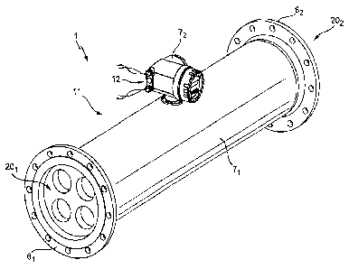
The measuring transducer includes a transducer housing, for
example, an essentially tubular and/or outwardly circularly
cylindrical, transducer housing, of which an inlet-side, first
housing end is formed by means of an inlet-side, first flow
divider having exactly four flow openings spaced, in each case,
from one another, for example, circularly cylindrical, or
conical, flow openings and an outlet-side, second housing end
formed by means of an outlet-side, second flow divider having
exactly four flow openings spaced, in each case, from one
another, for example, circularly cylindrical, or conical, flow
openings,
exactly four measuring tubes for conveying flowing
medium and connected to the flow dividers, for example,
equally-constructed, flow dividers, for forming flow paths
connected for parallel flow, for example, four such measuring
tubes held oscillatably in the transducer housing only by means
of said flow dividers and/or four such measuring tubes, which
are constructed equally to one another and/or four such
measuring tubes, which are at least pairwise parallel to one
9
CA 02808248 2015-02-17
78639-58
another and/or, four such measuring tubes, which are straight,
of which a first measuring tube, for example, a circularly
cylindrical, first measuring tube, opens with an inlet-side,
first measuring tube end into a first flow opening of the first
flow divider and with an outlet-side, second measuring tube end
into a first flow opening of the second flow divider, a second
measuring tube, for example, a circularly cylindrical, second
measuring tube, opens with an inlet-side, first measuring tube
end into a second flow opening of the first flow divider and
with an outlet-side, second measuring tube end into a second
flow opening of the second flow divider, a third measuring
tube, for example, a circularly cylindrical, third measuring
tube, opens with an inlet-side, first measuring tube end into a
third flow opening of the first flow divider and with an
outlet-side, second measuring tube end into a third flow
opening of the second flow divider and a fourth measuring tube,
for example, a circularly cylindrical, fourth measuring tube,
opens with an inlet-side, first measuring tube end into a
fourth flow opening of the first flow divider and with an
outlet-side, second measuring tube end into a fourth flow
opening of the second flow divider,
an electromechanical, exciter mechanism serving for
producing and/or maintaining mechanical oscillations, for
example, bending oscillations, of the four measuring tubes and
formed by means of a first oscillation exciter, for example, an
electrodynamic, first oscillation exciter and/or a first
oscillation exciter differentially exciting oscillations of the
first measuring tube relative to the second measuring tube,
wherein the exciter mechanism is embodied in such a manner
that, therewith, the first measuring tube and the second
CA 02808248 2015-02-17
78639-58
measuring tube are excitable during operation to opposite equal
bending oscillations in a shared, imaginary, first plane of
oscillation and the third measuring tube and the fourth
measuring tube are excited during operation to opposite equal
bending oscillations in a shared, imaginary, second plane of
oscillation, for example, a second plane of oscillation
essentially parallel to the first plane of oscillation, as well
as
a vibration sensor arrangement serving for producing
oscillation measurement signals representing vibrations, for
example, bending oscillations, of the measuring tubes, and
reacting to vibrations of the measuring tubes, especially
bending oscillations excited by means of the exciter mechanism,
for example, an electrodynamic, vibration sensor arrangement
and/or a vibration sensor arrangement formed by means of
oscillation sensors constructed equally to one another.
Moreover, the measuring system comprises a transmitter
electronics electrically coupled with the measuring transducer,
for example, a transmitter electronics arranged in an
electronics housing connected mechanically with the transducer
housing, for activating the measuring transducer, especially
its exciter mechanism, and for evaluating oscillation
measurement signals delivered by the measuring transducer.
The transmitter electronics includes a driver circuit for the
exciter mechanism, and
a measuring circuit formed, for example, by means of
a microcomputer and/or a digital signal processor. The
measuring circuit, with application of at least one oscillation
11
CA 02808248 2016-04-26
' 78639-58
measurement signal delivered by the vibration sensor
arrangement, generates a density measured value representing
the density of the medium and/or a mass flow measured value
representing its mass flow rate. In the case of the measuring
system of the invention, the measuring circuit, for producing
the density measured value and/or the mass flow measured value,
is additionally adapted to correct a change of at least one
characteristic variable (for example, a signal frequency) of
the oscillation measurement signals delivered by the measuring
transducer, for instance, a change of their signal frequency
and/or a change of a phase difference between two oscillation
measurement signals generated by means of the vibration sensor
arrangement, wherein said changes are caused 1) by a change of
a stress state in the measuring transducer, for instance, a
change of a stress state accompanying thermally related
deformation of the measuring transducer and/or deformation
effected by external forces, and/or 2) by a deviation of an
instantaneous stress state in the measuring transducer from a
therefor predetermined, reference stress state, for example, a
reference stress state ascertained earlier in the course of a
manufacturer side, calibration of the measuring system and/or a
calibration performed in the installed position, for instance,
such a deviation accompanying thermally related deformation of
the measuring transducer and/or deformation of the measuring
transducer effected by external forces.
According to an aspect of the present invention, there is
provided Measuring system for measuring at least one of:
density, mass flow rate, and viscosity of a medium flowing, at
least at times, in a pipeline, which measuring system
comprises: a measuring transducer of vibration-type for
12
CA 02808248 2016-04-26
78639-58
producing oscillation measurement signals, wherein the
measuring transducer includes a transducer housing of which an
inlet-side, first housing end is formed by means of an inlet-
side, first flow divider having exactly four, mutually spaced,
flow openings and an outlet-side, second housing end is formed
by means of an outlet-side, second flow divider having exactly
four, mutually spaced, flow openings; exactly four measuring
tubes, which are connected to the flow dividers for guiding
flowing medium along flow paths connected in parallel, of which
a first measuring tube opens with an inlet-side, first
measuring tube end into a first flow opening of the first flow
divider and with an outlet-side, second measuring tube end into
a first flow opening of the second flow divider, a second
measuring tube opens with an inlet-side, first measuring tube
end into a second flow opening of the first flow divider and
with an outlet-side, second measuring tube end into a second
flow opening of the second flow divider, a third measuring tube
opens with an inlet-side, first measuring tube end into a third
flow opening of the first flow divider and with an outlet-side,
second measuring tube end into a third flow opening of the
second flow divider and a fourth measuring tube opens with an
inlet-side, first measuring tube end into a fourth flow opening
of the first flow divider and with an outlet-side, second
measuring tube end into a fourth flow opening of the second
flow divider; and an electromechanical, exciter mechanism
formed by means of a first oscillation exciter for at least one
of: producing and maintaining mechanical oscillations of the
four measuring tubes, wherein the exciter mechanism is embodied
in such a manner that therewith the first measuring tube and
the second measuring tube are excitable during operation to
execute opposite equal bending oscillations in a shared,
12a
CA 02808248 2016-04-26
78639-58
imaginary, first plane of oscillation and the third measuring
tube and the fourth measuring tube during operation to opposite
equal bending oscillations in a shared, imaginary, second plane
of oscillation as well as a vibration sensor arrangement reacting
to vibrations of the measuring tubes for producing oscillation
measurement signals representing vibrations of the measuring
tubes; as well as a transmitter electronics electrically coupled
with the measuring transducer for activating the measuring
transducer and for evaluating oscillation measurement signals
delivered from the measuring transducer, which transmitter
electronics includes a driver circuit for the exciter mechanism,
and a measuring circuit, wherein the measuring circuit, with
application of at least one oscillation measurement signal
delivered from the vibration sensor arrangement, generates at
least one of: a density measured value representing the density
of the medium and a mass flow measured value representing the
mass flow rate, wherein the measuring circuit, for producing the
density measured value and the mass flow measured value,
respectively, corrects a change of at least one characteristic
variable of oscillation measurement signals delivered from the
measuring transducer, which changes are caused by at least one
of: a change of a stress state in the measuring transducer and a
deviation of an instantaneous stress state in the measuring
transducer from a reference stress state predetermined therefor.
Another aspect relates to use of such a measuring system for
measuring at least one of: density and mass flow rate of a medium
flowing in a pipeline, at least at times, with a mass flow rate
of more than 2200 t/h.
According to a first embodiment of the invention, it is
additionally provided that said change of the stress state in the
measuring transducer (especially a change influencing an
12b
CA 02808248 2016-04-26
' 78639-58
oscillatory behavior of the measuring tubes and/or effecting a
change of at least one resonance frequency of the measuring
12c
CA 02808248 2015-02-17
78639-58
transducer) to be corrected by means of the measuring circuit
and/or said deviation of the instantaneous stress state in the
measuring transducer from the reference stress state
predetermined therefor (especially such a deviation influencing
an oscillatory behavior of the measuring tubes and/or effecting
a change of at least one resonance frequency of the measuring
transducer) result(s) from a deformation (for instance, a
thermally related deformation and/or a deformation effected by
external forces) of the measuring transducer, for example, a
strain of one or a plurality of the measuring tubes.
According to a second embodiment of the invention, it is
additionally provided that the measuring circuit ascertains the
change of the stress state in the measuring transducer and/or
the deviation of the instantaneous stress state in the
measuring transducer from the reference stress state
predetermined therefor by means of at least one oscillation
measurement signal produced by the vibration sensor arrangement
and representing, for example, two- or multimodal vibrations,
especially bending oscillations, of the measuring tubes and
having, for example, two or more signal components of different
signal frequency. Alternatively or in supplementation, it is
additionally provided that the measuring circuit corrects the
change of the at least one characteristic variable of the
oscillation measurement signals delivered from the measuring
transducer (which change results from the change of the stress
state in the measuring transducer, or from the deviation of the
instantaneous stress state in the measuring transducer from the
reference stress state predetermined therefor) by means of at
least one oscillation measurement signal produced by the
vibration sensor arrangement, for example, a signal
13
CA 02808248 2015-02-17
78639-58
representing two- or multimodal vibrations, especially bending
oscillations, of the measuring tubes, and having, for example,
two or more signal components of different signal frequency.
According to a third embodiment of the invention, it is
additionally provided that each of the four measuring tubes,
especially measuring tubes of equal caliber and/or equal
length, has a caliber, which amounts to more than 60 mm,
especially more than 80 mm.
According to a fourth embodiment of the invention, is
additionally provided that the first flow divider has a flange,
especially a flange having mass of more than 50 kg, for
connecting the measuring transducer to a tubular segment of the
pipeline serving for supplying medium to the measuring
transducer and the second flow divider has a flange, especially
a flange having a mass of more than 50 kg, for connecting the
measuring transducer to a segment of the pipeline serving for
removing medium from the measuring transducer. Developing this
embodiment of the invention further, each of the flanges has a
sealing surface for fluid tight connecting of the measuring
transducer with the, in each case, corresponding tubular
segment of the pipeline, wherein a distance between the sealing
surfaces of both flanges defines an installed length of the
measuring transducer, especially an installed length amounting
to more than 1200 mm and/or less than 3000 mm. Especially, the
measuring transducer is additionally so embodied that, in such
case, a measuring tube length of the first measuring tube
corresponding to a minimum distance between the first flow
opening of the first flow divider and the first flow opening of
the second flow divider is so selected that a measuring tube
14
CA 02808248 2015-02-17
78639-58
length to installed length ratio of the measuring transducer,
as defined by a ratio of the measuring tube length of the first
measuring tube to the installed length of the measuring
transducer, amounts to more than 0.7, especially more than 0.8
and/or less than 0.95, and/or that a caliber to installed
length ratio of the measuring transducer, as defined by a ratio
of the caliber of the first measuring tube to the installed
length of the measuring transducer, amounts to more than 0.02,
especially more than 0.05 and/or less than 0.09. Alternatively
thereto or in supplementation thereof, the measuring transducer
is so embodied that a nominal diameter to installed length
ratio of the measuring transducer, as defined by a ratio of the
nominal diameter of the measuring transducer to the installed
length of the measuring transducer, is smaller than 0.3,
especially smaller than 0.2 and/or greater than 0.1, wherein
the nominal diameter corresponds to a caliber of the pipeline,
in whose course the measuring transducer is to be used.
In a fifth embodiment of the invention, it is additionally
provided that a measuring tube length of the first measuring
tube corresponding to a minimum distance between the first flow
opening of the first flow divider and the first flow opening of
the second flow divider amounts to more than 1000 mm,
especially more than 1200 mm and/or less than 2000 mm.
In a sixth embodiment of the invention, it is additionally
provided that each of the four measuring tubes, especially four
measuring tubes of equal caliber, is so arranged that a
smallest lateral separation of each of the four measuring
tubes, especially measuring tubes of equal length, from a
housing side wall of the transducer housing is, in each case,
CA 02808248 2015-02-17
78639-58
greater than zero, especially greater than 3 mm and/or greater
than twice a respective tube wall thickness; and/or that a
smallest lateral separation between two neighboring measuring
tubes amounts to, in each case, greater than 3 mm and/or
greater than the sum of their respective tube wall thicknesses.
In a seventh embodiment of the invention, it is additionally
provided that each of the flow openings is so arranged that a
smallest lateral separation of each of the flow openings from a
housing side wall of the transducer housing amounts, in each
case, to greater than zero, especially greater than 3 mm and/or
greater than twice a smallest tube wall thickness of the
measuring tubes; and/or that a smallest lateral separation
between the flow openings amounts to greater than 3 mm and/or
greater than twice a smallest tube wall thickness of the
measuring tubes.
According to an eighth embodiment of the invention, it is
additionally provided that a mass ratio of an empty mass of the
total measuring transducer to an empty mass of the first
measuring tube is greater than 10, especially greater than 15
and smaller than 25.
According to a ninth embodiment of the invention, it is
additionally provided that an empty mass, M18, of the first
measuring tube, especially of each of the measuring tubes is
greater than 20 kg, especially greater than 30 kg and/or less
than 50 kg.
According to a tenth embodiment of the invention, it is
additionally provided that an empty mass of the measuring
16
CA 02808248 2015-02-17
78639-58
transducer is greater than 200 kg, especially greater than 300
kg.
According to an eleventh embodiment of the invention, it is
additionally provided that a nominal diameter of the measuring
transducer, which corresponds to a caliber of the pipeline, in
whose course the measuring transducer is to be used, amounts to
more than 100 mm, especially is greater than 300 mm. In
advantageous manner, the measuring transducer is additionally
so embodied that a mass to nominal diameter ratio of the
measuring transducer, defined by a ratio of the empty mass of
the measuring transducer to the nominal diameter of the
measuring transducer is less than 2 kg/mm, especially less than
1 kg/mm and/or greater than 0.5 kg/mm.
In a twelfth embodiment of the invention, it is additionally
provided that the first and the second measuring tubes are of
equal construction, at least as regards a material, of which
their tube walls are, in each case, composed, and/or as regards
their geometrical tube dimensions, especially a tube length, a
tube wall thickness, a tube outer diameter and/or a caliber.
According to a thirteenth embodiment of the invention, it is
additionally provided that the third and fourth measuring tubes
are of equal construction, at least as regards a material, of
which their tube walls are, in each case, composed, and/or as
regards their geometric tube dimensions, especially a tube
length, a tube wall thickness, a tube outer diameter and/or a
caliber.
17
CA 02808248 2015-02-17
78639-58
According to a fourteenth embodiment of the invention, it is
additionally provided that the four measuring tubes are of
equal construction as regards a material, of which their tube
walls are composed, and/or as regards their geometric tube
dimensions, especially a tube length, a tube wall thickness, a
pipe outer diameter and/or a caliber. It can, however, also be
advantageous, when, alternatively thereto, both the third
measuring tube as well as also the fourth measuring tube are
different from the first measuring tube and the second
measuring tube as regards their respective geometric tube
dimensions, especially a tube length, a tube wall thickness, a
pipe outer diameter and/or a caliber.
In a fifteenth embodiment of the invention, it is additionally
provided that a material, of which the tube walls of the four
measuring tubes are at least partially composed, is titanium
and/or zirconium and/or duplex steel and/or super duplex steel.
According to a sixteenth embodiment of the invention, it is
additionally provided that the transducer housing, the flow
divider and tube walls of the measuring tubes are, in each
case, composed of steel, for example, stainless steel.
According to a seventeenth embodiment of the invention, it is
additionally provided that minimum bending oscillation
resonance frequencies at least of the first and second
measuring tube are essentially equal and minimum bending
oscillation resonance frequencies at least of the third and
fourth measuring tube are essentially equal. In such case, the
minimum bending oscillation resonance frequencies of all four
measuring tubes can be kept essentially equal or, however, also
kept only pairwise equal.
18
CA 02808248 2015-02-17
78639-58
According to an eighteenth embodiment of the invention, it is
additionally provided that the four flow openings of the first
flow divider are so arranged that imaginary areal centers of
gravity associated with cross sectional areas, especially
circularly shaped, cross sectional areas, of the flow openings
of the first flow divider form the vertices of an imaginary
square, wherein said cross sectional areas lie in a shared,
imaginary, cutting plane of the first flow divider extending
perpendicularly to a longitudinal axis of the measuring
transducer, especially a longitudinal axis extending parallel
to a principal flow axis of the measuring transducer.
In a nineteenth embodiment of the invention, it is additionally
provided that the four flow openings of the second flow divider
are so arranged that imaginary areal centers of gravity
associated with cross sectional areas, especially circularly
shaped, cross sectional areas, of the flow openings of the
second flow divider form the vertices of an imaginary square,
wherein said cross sectional areas lie in a shared, imaginary,
cutting plane of the second flow divider extending
perpendicularly to a longitudinal axis of the measuring
transducer, especially a longitudinal axis extending parallel
to a principal flow axis of the measuring transducer.
According to a twentieth embodiment of the invention, it is
additionally provided that a middle segment of the transducer
housing is formed by means of a straight tube, for example, a
circularly cylindrical straight tube.
According to a twenty-first embodiment of the invention, it is
additionally provided that the transducer housing is
essentially tubularly embodied, for example, circularly
19
CA 02808248 2015-02-17
78639-58
cylindrically embodied. In such case, it is additionally
provided that the transducer housing has a largest housing
inner diameter, which is greater than 150 mm, especially
greater than 250 mm, especially in such a manner that a housing
to measuring tube inner diameter ratio of the measuring
transducer, as defined by a ratio of the largest housing inner
diameter to a caliber of the first measuring tube is kept
greater than 3, especially greater than 4 and/or smaller than
5, and/or that a housing inner diameter to nominal diameter
ratio of the measuring transducer, as defined by a ratio of the
largest housing inner diameter to the nominal diameter of the
measuring transducer is smaller than 1.5, especially smaller
than 1.2 and/or greater than 0.9, wherein the nominal diameter
corresponds to a caliber of the pipeline, in whose course the
measuring transducer is to be used. The housing inner diameter
to nominal diameter ratio of the measuring transducer can, in
such case, in advantageous manner, be, for example, also equal
to one.
According to a twenty-second embodiment of the invention, it is
additionally provided that the vibration sensor arrangement is
formed by means of an inlet-side, first oscillation sensor,
especially an electrodynamic sensor and/or one differentially
registering oscillations of the first measuring tube relative
to the second measuring tube, as well as by means of an outlet-
side, second oscillation sensor, especially an electrodynamic
sensor and/or one differentially registering oscillations of
the first measuring tube relative to the second measuring tube,
especially in such a manner that a measuring length of the
measuring transducer corresponding to a minimum distance
between the first oscillation sensor and the second oscillation
CA 02808248 2015-02-17
78639-58
sensor amounts to more than 500 mm, especially more than 600 mm
and/or less than 1200 mm, and/or that a caliber to measuring
length ratio of the measuring transducer, defined by a ratio of
a caliber of the first measuring tube to the measuring length
of the measuring transducer amounts to more than 0.05,
especially more than 0.09. Additionally, the first oscillation
sensor can be formed by means of a permanent magnet held on the
first measuring tube and a cylindrical coil permeated by its
magnetic field and held on the second measuring tube, and the
second oscillation sensor by means of a permanent magnet held
on the first measuring tube and a cylindrical coil permeated by
its magnetic field and held on the second measuring tube.
According to a twenty-third embodiment of the invention, it is
additionally provided that the vibration sensor arrangement is
formed by means of an inlet-side, first oscillation sensor,
especially an electrodynamic sensor and/or one differentially
registering oscillations of the first measuring tube relative
to the second measuring tube, by means of an outlet-side,
second oscillation sensor, especially an electrodynamic sensor
and/or one differentially registering oscillations of the first
measuring tube relative to the second measuring tube, by means
of an inlet-side third oscillation sensor, especially an
electrodynamic sensor and/or one differentially registering
oscillations of the third measuring tube relative to the fourth
measuring tube, as well as by means of an outlet-side fourth
oscillation sensor, especially an electrodynamic sensor and/or
one differentially registering oscillations of the third
measuring tube relative to the fourth measuring tube, this, for
example, in such a manner that a measuring length of the
measuring transducer corresponding to a minimum distance
21
CA 02808248 2015-02-17
78639-58
between the first oscillation sensor and the second oscillation
sensor amounts to more than 500 mm, especially more than 600 mm
and/or less than 1200 mm, and/or that a caliber to measuring
length ratio of the measuring transducer, defined by a ratio of
a caliber of the first measuring tube to the measuring length
of the measuring transducer amounts to more than 0.05,
especially more than 0.09. In such case, in advantageous
manner, the first and third oscillation sensor can be
electrically interconnected serially in such a manner that a
common oscillation measurement signal represents shared inlet-
side oscillations of the first and third measuring tube
relative to the second and fourth measuring tube, and/or the
second and fourth oscillation sensor can be electrically
interconnected serially in such a manner that a common
oscillation measurement signal represents shared outlet-side
oscillations of the first and third measuring tube relative to
the second and fourth measuring tube. Alternatively or in
supplementation, additionally, the first oscillation sensor can
be formed by means of a permanent magnet held on the first
measuring tube and a cylindrical coil permeated by its magnetic
field and held on the second measuring tube, and the second
oscillation sensor by means of a permanent magnet held on the
first measuring tube and a cylindrical coil permeated by its
magnetic field and held on the second measuring tube, and/or
the third oscillation sensor by means of a permanent magnet
held on the third measuring tube and a cylindrical coil
permeated by its magnetic field and held on the fourth
measuring tube and the fourth oscillation sensor by means of a
permanent magnet held on the third measuring tube and a
cylindrical coil permeated by its magnetic field and held on
the fourth measuring tube.
22
CA 02808248 2015-02-17
78639-58
According to a twenty-fourth embodiment of the invention, the
exciter mechanism is formed by means of a second oscillation
exciter, for example, an electrodynamic exciter and/or one
exciting oscillations of the third measuring tube relative to
the fourth measuring tube differential. In such case, it is
additionally provided that the first and second oscillation
exciters are electrically serially interconnected in such a
manner that a common driver signal excites shared oscillations
of the first and third measuring tube relative to the second
and fourth measuring tube. The oscillation exciter of the
exciter mechanism can, for example, be formed by means of a
permanent magnet held on the first measuring tube and a
cylindrical coil permeated by its magnetic field and held on
the second measuring tube, and wherein the second oscillation
exciter can, for example, be formed by means of a permanent
magnet held on the third measuring tube and a cylindrical coil
permeated by its magnetic field and held on the fourth
measuring tube.
According to a first further development of the invention, the
measuring transducer further comprises: A first, plate shaped,
stiffening element, which, for tuning resonance frequencies of
bending oscillations of the first measuring tube and the third
measuring tube in a third plane of oscillation essentially
perpendicular to the first and/or second plane of oscillation,
is affixed to the first measuring tube and to the third
measuring tube, and, indeed, in each case, to a segment of the
first, or third measuring tube lying between the first
oscillation exciter and the first flow divider; a second, plate
shaped, stiffening element, which, for tuning resonance
frequencies of bending oscillations of the second measuring
23
CA 02808248 2015-02-17
78639-58
tube and the fourth measuring tube in a fourth plane of
oscillation essentially perpendicular to the first and/or
second plane of oscillation, is affixed to the second measuring
tube and to the fourth measuring tube, and, indeed, in each
case, to a segment of the second, or fourth measuring tube
lying between the first oscillation exciter and the first flow
divider; a third, plate shaped, stiffening element, which, for
tuning resonance frequencies of bending oscillations of the
first measuring tube and the third measuring tube in the third
plane of oscillation, is affixed to the first measuring tube
and to the third measuring tube, and, indeed, in each case, to
a segment of the first, or third measuring tube lying between
the first oscillation exciter and the second flow divider; as
well as a fourth, plate shaped, stiffening element, which for
tuning resonance frequencies of bending oscillations of the
second measuring tube and the fourth measuring tube in the
fourth plane of oscillation, is affixed to the second measuring
tube and to the fourth measuring tube, and, indeed, in each
case, to a segment of the second, or fourth measuring tube
lying between the first oscillation exciter and the second flow
divider. The plate shaped stiffening elements can, for the
case, in which the vibration sensor arrangement is formed by
means of an inlet-side, first oscillation sensor and by means
of an outlet-side, second oscillation sensor, be arranged e.g.
in such a manner in the measuring transducer that the first
plate shaped stiffening element is affixed to the segment of
the first measuring tube lying between the first oscillation
sensor and the first flow divider along one of the straight
lateral surface elements of the first measuring tube -, for
instance, that nearest the third measuring tube - as well as to
the segment of the third measuring tube lying between the first
24
CA 02808248 2015-02-17
78639-58
oscillation sensor and the first flow divider along one of the
straight lateral surface elements of the third measuring tube -
, for instance, that nearest the first measuring tube -, the
second plate shaped stiffening element is affixed to the
segment of the second measuring tube lying between the first
oscillation sensor and the first flow divider along one of the
straight lateral surface elements of the second measuring tube
-, for instance, that nearest the fourth measuring tube - as
well as to the segment of the fourth measuring tube lying
between the first oscillation sensor and the first flow divider
along one of the straight lateral surface elements of the
fourth measuring tube -, for instance, that nearest the second
measuring tube -, the third plate shaped stiffening element is
affixed to the segment of the first measuring tube lying
between the second oscillation sensor and the second flow
divider along one of the straight lateral surface elements of
the first measuring tube -, for instance, that nearest the
third measuring tube - as well as to the segment of the third
measuring tube lying between the second oscillation sensor and
the second flow divider along one of the straight lateral
surface elements of the third measuring tube -, for instance,
that nearest the first measuring tube -, and the fourth plate
shaped stiffening element is affixed to the segment of the
second measuring tube lying between the second oscillation
sensor and the second flow divider along one of the straight
lateral surface elements of the second measuring tube -, for
instance, that nearest the fourth measuring tube - as well as
to the segment of the fourth measuring tube lying between the
second oscillation sensor and the second flow divider along one
of the straight lateral surface elements of the fourth
measuring tube -, for instance, that nearest the second
CA 02808248 2015-02-17
78639-58
measuring tube. Additionally, it is provided, in such case,
that each of the four plate shaped stiffening elements, for
example, plate shaped stiffening elements of equal
construction, is so embodied and so placed in the measuring
transducer that it has a height corresponding to a smallest
distance between the lateral surface elements of those two
measuring tubes, along which it is, in each case, affixed,
which height is smaller, especially by more than half, than a
length of said plate shaped stiffening element measured in the
direction of said lateral surface element. In supplementation
thereto, each of the four plate shaped stiffening elements can
additionally, in each case, be so embodied that the length of
each of the plate shaped stiffening elements is greater,
especially by more than twice, than a thickness of the said
plate shaped stiffening element.
According to a second further development of the invention, the
measuring transducer further comprises a plurality of annular,
especially equally-constructed, stiffening elements serving for
increasing the oscillation quality factor of the measuring
tubes, of which each is so placed on exactly one of the
measuring tubes that it grips around this along one of its
peripheral surface elements. According to an embodiment of the
second further development of the invention, there are on each
of the measuring tubes at least four annular, for example,
equally constructed, stiffening elements, placed especially in
such a manner that the stiffening elements are so placed in the
measuring transducer that two adjoining stiffening elements
mounted on the same measuring tube are separated by a distance,
which amounts to at least 70% of a pipe outer diameter of said
measuring tube, at most, however, 150% of such pipe outer
26
CA 02808248 2015-02-17
78639-58
diameter, for example, a distance in the range of 80% to 120%
of such pipe outer diameter.
According to a third further development of the invention, the
measuring system further comprises a temperature measuring
arrangement, for example, a temperature measuring arrangement
formed by means of a affixed resistance thermometer on one of
the measuring tubes and/or by means of a resistance thermometer
affixed on the transducer housing and/or electrically connected
with the transmitter electronics, for registering a temperature
of the measuring transducer, for example, a temperature of one
or a plurality of the measuring tubes, especially a temperature
influencing an oscillatory behavior of the measuring tubes
and/or effecting a change of at least one resonance frequency
of at least one of the measuring tubes.
According to a first embodiment of the third further
development of the invention, it is additionally provided that
the temperature measuring arrangement is formed by means of a
resistance thermometer, for example, a resistance thermometer
affixed on one of the measuring tubes, wherein the resistance
thermometer has an ohmic resistance dependent on a temperature
of the measuring transducer, for example, a temperature of one
of the measuring tubes.
According to a second embodiment of the third further
development of the invention, it is additionally provided that
the measuring circuit ascertains the change of the stress state
in the measuring transducer and/or the deviation of the
instantaneous stress state in the measuring transducer from the
reference stress state predetermined therefor based on a
temperature of the measuring transducer, for example, a
27
CA 02808248 2015-02-17
78639-58
temperature of one or a plurality of the measuring tubes,
registered by the temperature measuring arrangement, especially
a temperature influencing an oscillatory behavior of the
measuring tubes and/or effecting a change of at least one
resonance frequency of at least one of the measuring tubes.
According to a third embodiment of the third further
development of the invention, it is additionally provided that
the measuring circuit corrects the change of the at least one
characteristic variable of the oscillation measurement signals
delivered from the measuring transducer (which change results
from the change of the stress state in the measuring
transducer, or the deviation of the instantaneous stress state
in the measuring transducer from the reference stress state
predetermined therefor) based on a temperature of the measuring
transducer, for example, a temperature of one or a plurality of
the measuring tubes, registered by the temperature measuring
arrangement, especially a temperature influencing an
oscillatory behavior of the measuring tubes and/or effecting a
change of at least one resonance frequency of at least one of
the measuring tubes.
According to a fourth further development of the invention, the
measuring transducer further comprises a first coupling element
of first type, especially a plate-shaped first coupling element
of first type, which is affixed at least to the first measuring
tube and to the second measuring tube and spaced on the inlet
side both from the first flow divider as well as also from the
second flow divider for forming inlet-side, oscillation nodes
at least for vibrations, especially bending oscillations, of
the first measuring tube and for thereto opposite equal
28
CA 02808248 2015-02-17
78639-58
vibrations, especially bending oscillations, of the second
measuring tube, as well as a second coupling element of first
type, especially a plate-shaped second coupling element of
first type and/or a second coupling element constructed equally
to the first coupling element and/or a second coupling element
parallel to the first coupling element, which second coupling
element of first type is affixed at least to the first
measuring tube and to the second measuring tube and spaced on
the outlet side both from the first flow divider as well as
also from the second flow divider, as well as also from the
first coupling element, for forming outlet-side, oscillation
nodes at least for vibrations, especially bending oscillations,
of the first measuring tube and for thereto opposite equal
vibrations, especially bending oscillations, of the second
measuring tube.
In a first embodiment of the fourth further
development of the invention, it is additionally provided that
all four measuring tubes are connected with one another
mechanically by means of the first coupling element of first
type as well as by means of the second coupling element of
first type.
In a second embodiment of the fourth further
development of the invention, it is additionally provided that
the first coupling element of first type is plate shaped,
especially in such a manner that it has essentially a
rectangular, square, round, cross, or X, shaped or H shaped,
basic shape.
In a third embodiment of the fourth further
development of the invention, it is additionally provided that
29
CA 02808248 2015-02-17
78639-58
the second coupling element of first type, especially a
coupling element of construction equal to that of the first
coupling element of first type, is plate shaped, especially in
such a manner that it has a rectangular, square, round, cross,
or X, shaped or H shaped, basic shape.
In a fourth embodiment of the fourth further
development of the invention, it is additionally provided that
the first coupling element of first type is affixed also to the
third measuring tube and to the fourth measuring tube, and that
the second coupling element of first type is affixed to the
third measuring tube and to the fourth measuring tube.
In a fifth embodiment of the fourth further
development of the invention, it is additionally provided that
a center of mass of the first coupling element of first type
has a distance to a center of mass of the measuring transducer,
which is essentially equal to a distance of a center of mass of
the second coupling element of first type to said center of
mass of the measuring transducer.
In a sixth embodiment of the fourth further
development of the invention, the measuring transducer is
additionally so embodied that a free, oscillatory length, L19x,
of the first measuring tube, especially of each of the
measuring tubes, corresponding to a minimum separation between
the first coupling element of first type and the second
coupling element of first type, amounts to less than 2500 mm,
especially less than 2000 mm and/or more than 800 mm.
Especially, the measuring transducer is, in such case,
additionally so embodied that each of the four measuring tubes,
especially measuring tubes of equal caliber and/or equal
CA 02808248 2015-02-17
78639-58
length, has a caliber, which amounts to more than 60 mm,
especially more than 80 mm, especially in such a manner that a
caliber to oscillatory length ratio of the measuring
transducer, as defined by a ratio of the caliber of the first
measuring tube to the free, oscillatory length of the first
measuring tube, amounts to more than 0.07, especially more than
0.09 and/or less than 0.15.
In supplementation to the fourth further development
of the invention, it is additionally provided that the
measuring transducer further comprises: A third coupling
element of first type, for example, a plate shaped, third
coupling element of first type, which, for forming inlet-side
oscillation nodes at least for vibrations, especially bending
oscillations, of the third measuring tube and thereto opposite-
equal vibrations, especially bending oscillations, of the
fourth measuring tube, is affixed on the inlet side at least to
the third measuring tube and to the fourth measuring tube and
spaced both from the first flow divider as well as also from
the second flow divider; as well as a fourth coupling element
of first type, for example, a plate shaped, fourth coupling
element of first type, which, for forming outlet-side
oscillation nodes at least for vibrations, especially bending
oscillations, of the third measuring tube and thereto opposite-
equal vibrations, especially bending oscillations, of the
fourth measuring tube, is affixed on the outlet side at least
to the third measuring tube and to the fourth measuring tube
and spaced both from the first flow divider as well as also
from the second flow divider, as well as also from the third
coupling element of first type. In such case, for example,
also all four measuring tubes can be mechanically connected
31
CA 02808248 2015-02-17
78639-58
with one another by means of the third coupling element of
first type as well as by means of the fourth coupling element
of first type. Additionally, the first and third coupling
element of first type can be connected with one another
supplementally with a first coupler connecting element (for
example, a rod- or, plate shaped, first coupler connecting
element and/or a first coupler connecting element extending
parallel to the measuring tubes) affixed both to the first
coupling element of first type as well as also to the third
coupling element of first type and the second and fourth
coupling element of first type can be connected with one
another supplementally with a second coupler connecting element
(for example, rod- or, plate shaped, second coupler connecting
element and/or a second coupler connecting element extending
parallel to the measuring tubes) affixed both to the second
coupling element of first type as well as also to the fourth
coupling element of first type.
In a fifth further development of the invention, the measuring
transducer additionally comprises a first coupling element of
second type, for example, a plate shaped or rod shaped, first
coupling element of second type, which is affixed to the first
measuring tube and to the third measuring tube and otherwise to
none other of the measuring tubes and spaced both from the
first coupling element of first type as well as also from the
second coupling element of first type for synchronizing
vibrations, especially bending oscillations, of the first
measuring tube and thereto equal frequency vibrations,
especially bending oscillations, of the third measuring tube,
as well as a second coupling element of second type, for
example, a plate shaped or rod shaped, second coupling element
32
CA 02808248 2015-02-17
78639-58
of second type, which is affixed to the second measuring tube
and to the fourth measuring tube and otherwise to none other of
the measuring tubes and spaced both from the first coupling
element of first type as well as also from the second coupling
element of first type, as well as also from the first coupling
element of second type, especially in such a manner that the
first and second coupling elements of second type are placed in
the measuring transducer lying opposite one another, for
synchronizing vibrations, especially bending oscillations, of
the second measuring tube and thereto equal frequency
vibrations, especially bending oscillations, of the fourth
measuring tube. In supplementation thereof, the measuring
transducer can further comprise a third coupling element of
second type, for example, a plate shaped or rod shaped, third
coupling element of second type, which is affixed to the first
measuring tube and to the third measuring tube and otherwise to
none other of the measuring tubes and spaced from the first
coupling element of second type, for synchronizing vibrations,
especially bending oscillations, of the first measuring tube
and thereto equal frequency vibrations, especially bending
oscillations, of the third measuring tube, as well as a fourth
coupling element of second type, for example, a plate shaped or
rod shaped, fourth coupling element of second type, which is
affixed to the second measuring tube and to the fourth
measuring tube and otherwise to none other of the measuring
tubes and spaced, in each case, from the second and third
coupling elements of second type, especially in such a manner
that the third and fourth coupling elements of second type are
placed lying opposite one another in the measuring transducer,
for synchronizing vibrations, especially bending oscillations,
of the second measuring tube and thereto equal frequency
33
CA 02808248 2015-02-17
78639-58
vibrations, especially bending oscillations, of the fourth
measuring tube.
Moreover, the measuring transducer can comprise,
additionally, a fifth coupling element of second type, for
example, a plate shaped or rod shaped, fifth coupling element
of second type, which is affixed to the first measuring tube
and to the third measuring tube and otherwise to none other of
the measuring tubes and spaced from the first and third
coupling elements of second type, for synchronizing vibrations,
especially bending oscillations, of the first measuring tube
and thereto equal frequency vibrations, especially bending
oscillations, of the third measuring tube, as well as a, for
example, a plate shaped or rod shaped, sixth coupling element
of second type, which is affixed to the second measuring tube
and to the fourth measuring tube and otherwise to none other of
the measuring tubes and spaced, in each case, from the second,
fourth and fifth coupling elements of second type, especially
in such a manner that the fifth and sixth coupling elements of
second type are placed in the measuring transducer lying
opposite one another, for synchronizing vibrations, especially
bending oscillations, of the second measuring tube and thereto
equal frequency vibrations, especially bending oscillations, of
the fourth measuring tube.
According to a sixth further development of the invention, the
measuring system further comprises a deformation measuring
arrangement, for instance, one electrically connected with the
transmitter electronics and/or mechanically coupled with at
least one of the measuring tubes, for registering deformation
of the measuring transducer, for instance, thermally related
34
CA 02808248 2015-02-17
78639-58
deformation and/or deformation effected by forces acting
externally on the measuring transducer and/or deformation
influencing an oscillatory behavior of the measuring tubes
and/or effecting a change of at least one resonance frequency
of at least one of the measuring tubes and/or a translational
deformation, especially a strain of one or a plurality of the
measuring tubes.
According to a first embodiment of the sixth further
development of the invention, it is additionally provided that
the deformation measuring arrangement is formed by means of a
sensor element, for example, in the form of semiconductor
strain gages or as metal foil strain gages formed, which has an
ohmic resistance dependent on deformation of the measuring
transducer, for example, a strain of one or a plurality of the
measuring tubes.
According to a second embodiment of the sixth further
development of the invention, it is additionally provided that
the deformation measuring arrangement is formed by means of a
sensor element, for example, in the form of semiconductor
strain gages or metal foil strain gages, which has an ohmic
resistance dependent on deformation of the measuring
transducer, for example, a strain of one or a plurality of the
measuring tubes, and that the sensor element, for instance,
embodied as strain gages, is affixed, for example, adhesively,
on one of the measuring tubes, for instance, in such a manner
that it reacts to changes of a measuring tube length of the
said measuring tube corresponding to a respective minimum
distance between the flow opening of the first flow divider
corresponding to the respective first measuring tube end and
CA 02808248 2015-02-17
78639-58
the flow opening of the second flow divider corresponding to
the respective second measuring tube end with a change of its
ohmic resistance and/or in such a manner that it is connected
flushly with said measuring tube.
According to a third embodiment of the sixth further
development of the invention, it is additionally provided that
the at least one sensor element, embodied, for example, as
strain gages, is affixed, for example, adhesively, on an outer
surface of the wall of the said measuring tube.
According to a fourth embodiment of the sixth further
development of the invention, it is additionally provided that
the at least one sensor element, embodied, for example, as
strain gages, is affixed, for example, adhesively on an outer
surface of the wall of the said measuring tube. This,
especially, in such a manner that it at least partially flushly
contacts a detection region covered thereby on the surface of
the wall of said tube; and/or that it is connected flushly with
a detection region covered thereby on the surface of the wall
of said tube; and/or that a detection region on the surface of
the wall of said tube covered by the sensor element, for
example, contacted flushly by this and/or connected flushly
therewith, has at least one zone, in which the opposite equal
bending oscillations excited by means of the exciter mechanism
result in no bending stress.
According to a fifth embodiment of the sixth further
development of the invention, it is additionally provided that
- considering that each of the measuring tubes, in each case,
has a measuring tube length, which corresponds to a respective
minimum distance between the flow opening of the first flow
36
CA 02808248 2015-02-17
78639-58
divider corresponding to the respective first measuring tube
end and the flow opening of the second flow divider
corresponding to the respective second measuring tube end -
changes of a measuring tube length of one or a plurality of the
measuring tubes are registerable by means of the deformation
measuring arrangement. For registering changes of the
measuring tube length of one or a plurality of the measuring
tubes, the deformation measuring arrangement can have at least
one strain gage, for example, a semiconductor strain gage or a
metal foil strain gage, affixed, for example, adhesively and/or
flushly, for instance, externally, on one of the measuring
tubes.
According to a sixth embodiment of the sixth further
development of the invention, it is additionally provided that
the deformation measuring arrangement is formed by means of at
least one strain gage, for example, a semiconductor strain gage
or a metal foil strain gage, mechanically coupled with at least
one of the measuring tubes, for example, affixed adhesively to
one of the measuring tubes.
According to a seventh embodiment of the sixth
further development of the invention, it is additionally
provided that the measuring circuit ascertains the change of
the stress state in the measuring transducer and/or the
deviation of the instantaneous stress state in the measuring
transducer from the reference stress state predetermined
therefor based on deformation of the measuring transducer (for
instance, thermally related deformation and/or deformation
effected by forces acting externally on the measuring
transducer and/or deformation influencing an oscillatory
37
CA 02808248 2015-02-17
78639-58
behavior of the measuring tubes and/or deformation effecting a
change of at least one resonance frequency of at least one of
the measuring tubes and/or translational deformation),
especially a strain of one or a plurality of the measuring
tubes, registered by the deformation measuring arrangement.
According to an eighth embodiment of the sixth
further development of the invention, it is additionally
provided that the measuring circuit corrects the change of the
at least one characteristic variable of the oscillation
measurement signals delivered from the measuring transducer
resulting from the change of the stress state in the measuring
transducer, or the deviation of the instantaneous stress state
in the measuring transducer from the reference stress state
predetermined therefor, based on a deformation of the measuring
transducer, especially a strain of one or a plurality of the
measuring tubes, registered by the deformation measuring
arrangement, for example, thermally related deformation and/or
deformation effected by forces acting externally on the
measuring transducer and/or deformation influencing an
oscillatory behavior of the measuring tubes and/or deformation
effecting a change of at least one resonance frequency of at
least one of the measuring tubes and/or translational
deformation.
According to a ninth embodiment of the sixth further
development of the invention, it is additionally provided that
the deformation measuring arrangement is formed by means of a
first sensor element, for example, in the form of semiconductor
strain gages or metal foil strain gages, having an ohmic
resistance dependent on deformation of the measuring
38
CA 02808248 2015-02-17
78639-58
transducer, and by means of at least a second sensor element,
for example, in the form of semiconductor strain gages or metal
foil strain gages, having an ohmic resistance dependent on
deformation of the measuring transducer, for example, in such a
manner that the first sensor element and the second sensor
element are electrically connected with one another by means of
at least one wire extending within the transducer housing,
and/or that the first sensor element and the second sensor
element are electrically serially interconnected, and/or that
the first sensor element and the second sensor element are of
equal construction, and/or that the first sensor element and
the second sensor element lie in an imaginary cutting plane of
the measuring transducer, in which a longitudinal axis of the
measuring transducer extends parallel to a principal flow axis
of the measuring transducer. Developing this embodiment of the
invention further, it is additionally provided that the first
sensor element of the deformation measuring arrangement is
affixed on the first measuring tube, for example, in such a
manner that, by means of the first sensor element, a strain of
the first measuring tube changing the measuring tube length of
the first measuring tube is registerable. In supplementation
thereto, the second sensor element of the deformation measuring
arrangement can be affixed on other than the first measuring
tube, especially on the measuring tube spaced laterally the
farthest therefrom, for example, in such a manner that, by
means of the sensor element, a strain of the fourth measuring
tube changing the measuring tube length of the fourth measuring
tube is registerable.
According to a tenth embodiment of the sixth further
development of the invention, it is additionally provided that
39
CA 02808248 2015-02-17
78639-58
the measuring transducer further comprises: A first, plate
shaped, stiffening element, which, for tuning resonance
frequencies of bending oscillations of the first measuring tube
and the third measuring tube in a third plane of oscillation
essentially perpendicular to the first and/or second plane of
oscillation, is affixed to the first measuring tube and to the
third measuring tube, and, indeed, in each case, to a segment
of the first, or third measuring tube lying between the first
oscillation exciter and the first flow divider; a second, plate
shaped, stiffening element, which, for tuning resonance
frequencies of bending oscillations of the second measuring
tube and the fourth measuring tube in a fourth plane of
oscillation essentially perpendicular to the first and/or
second plane of oscillation, is affixed to the second measuring
tube and to the fourth measuring tube, and, indeed, in each
case, to a segment of the second, or fourth measuring tube
lying between the first oscillation exciter and the first flow
divider; a third, plate shaped, stiffening element, which, for
tuning resonance frequencies of bending oscillations of the
first measuring tube and the third measuring tube in the third
plane of oscillation, is affixed to the first measuring tube
and to the third measuring tube, and, indeed, in each case, to
a segment of the first, or third measuring tube lying between
the first oscillation exciter and the second flow divider; as
well as a fourth, plate shaped, stiffening element, which for
tuning resonance frequencies of bending oscillations of the
second measuring tube and the fourth measuring tube in the
fourth plane of oscillation, is affixed to the second measuring
tube and to the fourth measuring tube, and, indeed, in each
case, to a segment of the second, or fourth measuring tube
lying between the first oscillation exciter and the second flow
CA 02808248 2015-02-17
78639-58
divider; and that the at least one sensor element of the
deformation measuring arrangement is affixed on one of the
stiffening elements, for example, in such a manner that the
sensor element reacts to a strain of the measuring tubes
connected with said stiffening element by changing its ohmic
resistance.
According to an eleventh embodiment of the sixth
further development of the invention, it is additionally
provided that the measuring transducer further comprises: A
first, plate shaped, stiffening element, which, for tuning
resonance frequencies of bending oscillations of the first
measuring tube and the third measuring tube in a third plane of
oscillation essentially perpendicular to the first and/or
second plane of oscillation, is affixed to the first measuring
tube and to the third measuring tube, and, indeed, in each
case, to a segment of the first, or third measuring tube lying
between the first oscillation exciter and the first flow
divider; a second, plate shaped, stiffening element, which, for
tuning resonance frequencies of bending oscillations of the
second measuring tube and the fourth measuring tube in a fourth
plane of oscillation essentially perpendicular to the first
and/or second plane of oscillation, is affixed to the second
measuring tube and to the fourth measuring tube, and, indeed,
in each case, to a segment of the second, or fourth measuring
tube lying between the first oscillation exciter and the first
flow divider; a third, plate shaped, stiffening element, which,
for tuning resonance frequencies of bending oscillations of the
first measuring tube and the third measuring tube in the third
plane of oscillation, is affixed to the first measuring tube
and to the third measuring tube, and, indeed, in each case, to
41
CA 02808248 2015-02-17
78639-58
a segment of the first, or third measuring tube lying between
the first oscillation exciter and the second flow divider; as
well as a fourth, plate shaped, stiffening element, which for
tuning resonance frequencies of bending oscillations of the
second measuring tube and the fourth measuring tube in the
fourth plane of oscillation, is affixed to the second measuring
tube and to the fourth measuring tube, and, indeed, in each
case, to a segment of the second, or fourth measuring tube
lying between the first oscillation exciter and the second flow
divider; and that the deformation measuring arrangement is
formed by means of a first sensor element, for example, in the
form of semiconductor strain gages or metal foil strain gages,
having an ohmic resistance dependent on deformation of the
measuring transducer, and by means of at least a second sensor
element, for example, in the form of semiconductor strain gages
or metal foil strain gages, having an ohmic resistance
dependent on deformation of the measuring transducer, for
example, in such a manner that the first sensor element of the
deformation measuring arrangement is affixed to the first
stiffening element, for instance, in such a manner that the
first sensor element reacts to a strain of the first and/or
third measuring tube by changing its ohmic resistance, and/or
that the second sensor element of the deformation measuring
arrangement is affixed to the second stiffening element,
especially in such a manner that the second sensor element
reacts to a strain of the second and/or fourth measuring tube
by changing its ohmic resistance.
According to a twelfth embodiment of the sixth
further development of the invention, it is additionally
provided that the measuring transducer further comprises a
42
CA 02808248 2015-02-17
78639-58
coupler connecting element affixed both to the first coupling
element of first type as well as also to the third coupling
element of first type, for example, a rod, or plate, shaped,
coupler connecting element and/or a coupler connecting element
extending parallel to the measuring tubes, and that the at
least one sensor element of the deformation measuring
arrangement is affixed on the coupler connecting element, for
instance, in such a manner that the sensor element reacts to a
strain of one or a plurality of the measuring tubes by changing
its ohmic resistance.
According to a thirteenth embodiment of the sixth
further development of the invention, it is additionally
provided that the measuring transducer further comprises: A
first coupler connecting element affixed both to the first
coupling element of first type as well as also to the third
coupling element of first type, for example, a rod, or plate,
shaped, first coupler connecting element and/or a first coupler
connecting element extending parallel to the measuring tubes;
as well as a second coupler connecting element affixed both to
the second as well as also to the fourth coupling element, for
example, a rod, or plate, shaped, second coupler connecting
element and/or a second coupler connecting element extending
parallel to the measuring tubes and/or one constructed equally
to the first coupler connecting element; and that the
deformation measuring arrangement is formed by means of a first
sensor element, for example, in the form of semiconductor
strain gages or metal foil strain gages, having an ohmic
resistance dependent on deformation of the measuring
transducer, and by means of at least a second sensor element,
for example, in the form of semiconductor strain gages or metal
43
CA 02808248 2015-02-17
78639-58
foil strain gages, having an ohmic resistance dependent on
deformation of the measuring transducer, in such a manner that
the first sensor element of the deformation measuring
arrangement is affixed on the first coupler connecting element,
for instance, in such a manner that the first sensor element
reacts to a strain of one or a plurality of the measuring tubes
by changing its ohmic resistance, and/or that the second sensor
element of the deformation measuring arrangement is affixed to
the second coupler connecting element, especially in such a
manner that the second sensor element reacts to a strain of one
or a plurality of the measuring tubes by changing its ohmic
resistance.
A basic idea of the invention is to use, instead of the two
measuring tubes flowed through in parallel used in the case of
conventional measuring transducers of large nominal diameter,
four straight measuring tubes flowed through in parallel, and
so, on the one hand, to enable an optimal exploitation of
limited space, while, on the other hand, to be able to assure
an acceptable pressure loss over a broad measuring range,
especially also in the case of very high mass flow rates of far
over 2200 t/h, at still very high accuracy of measurement.
This, especially, also in applications with operationally
widely fluctuating temperature ranges of more than 100K and/or
in application with strong mechanical loading of the measuring
transducer, for instance, as a result of axial forces or also
pipeline forces acting asymmetrically on the measuring
transducer. Moreover, the effective flow cross section of the
inner part resulting from the total cross section of the four
measuring tubes can be directly increased by more than 20% in
comparison to conventional only two measuring tubes having
44
CA 02808248 2015-02-17
78639-58
measuring transducers of equal nominal diameter and equal empty
mass. A further advantage of the measuring transducer of the
invention is that predominantly established structural designs,
as, for instance, as regards the used materials, the joining
technology, the manufacturing steps etc., can be applied as is
or only slightly modified, whereby also the manufacturing
costs, as a whole, are quite comparable to those of
conventional measuring transducers. Thus, the invention not
only creates an opportunity to construct comparatively compact
measuring transducers of vibration-type nevertheless with large
nominal diameters of over 150 mm, especially with a nominal
diameter of greater 250 mm, with manageable geometric
dimensions and empty masses, but, also this permits this to be
done with economically sensible budgets.
The measuring system of the invention, is due to its
potentially large nominal diameter, on the one hand, and its
relative small pressure loss, on the other hand, especially
suitable for measuring flowable media, which are conveyed in a
pipeline with a caliber of greater 150 mm, especially of 300 mm
or greater, and at least at times with mass flow rates of more
than 2200 t/h, especially also of more than 2500 t/h, as is
quite usual especially in applications for measuring petroleum,
natural gas or other petrochemical substances.
The invention, as well as other advantageous embodiments
thereof, will now be explained in greater detail on the basis
of examples of embodiments presented in the figures of the
drawing. Equal parts are provided in the figures with equal
reference characters; when required to avoid clutter or when it
otherwise appears sensible, already mentioned reference
CA 02808248 2015-02-17
78639-58
characters are omitted in subsequent figures. Other
advantageous embodiments or further developments, especially
also combinations of first only individually explained aspects
of the invention, will become evident additionally from the
figures of the drawing, as well as also alone from the
dependent claims. In particular, the figures of the drawing
show as follows:
Figs. 1,2 a measuring system - here in the form of an in-line
measuring device in compact construction - serving, for
example, as a Coriolis flow/density/viscosity transducer, in
perspective, also partially sectioned, side views;
Figs. 3a,ba projection of the measuring system of Fig. 1 in two
different side views;
Fig. 4 in perspective, a side view of a measuring transducer
of vibration-type as component of a measuring system of Fig. 1;
Figs. 5a,bprojection of the measuring transducer of Fig. 4 in
two different side views;
Figs. 6a,bprojections of an inner part of the measuring
transducer of Fig. 4 in two different side views;
Fig. 7 in perspective side view, a further development of
the measuring transducer according to Fig. 4, as a component of
a measuring system according to Fig. 1;
Figs. 8a,bprojection of the measuring transducer according to
Fig. 7 in two different side views; and
46
CA 02808248 2015-02-17
78639-58
Fig. 9
a side view of a further development of an inner part
for a measuring transducer according to Fig. 4.
Figs. 1, 2 show, schematically, a measuring system 1,
especially a measuring system embodied as a Coriolis, mass
flow, and/or density, measuring device, which serves for
registering a mass flow m of a medium flowing in a pipeline
(not shown) and for representing such in a mass flow, measured
value representing this mass flow instantaneously. The medium
can be practically any flowable material, for example, a
powder, a liquid, a gas, a vapor, or the like. Alternatively
or in supplementation, the measuring system 1 can, in given
cases, also be used for measuring a density p and/or a
viscosity ri of the medium. Especially, the measuring system 1
- here in the form of an in-line measuring device in compact
construction - is provided for measuring media, such as e.g.
petroleum, natural gas or other petrochemical materials, which
are flowing in a pipeline having a caliber greater than 250 mm,
especially a caliber of 300 mm or more. Especially, the
measuring system is also provided for measuring flowing media
of the aforementioned type, which are caused to flow with a
mass flow rate of greater than 2200 t/h, especially greater
than 2500 t/h.
The measuring system 1 comprises, for such purpose: A measuring
transducer 11 of vibration-type, through which the medium being
measured flows during operation; as well as, electrically
connected with the measuring transducer 11, a transmitter
electronics 12, which is here not shown in detail, but, instead
only schematically in the form of an enclosed unit. In
advantageous manner, the transmitter electronics 12 is so
47
CA 02808248 2015-02-17
78639-58
designed that, during operation of the measuring system 1, it
can exchange measuring and/or other operating data with a
measured value processing unit superordinated to it, for
example, a programmable logic controller (PLC), a personal
computer and/or a work station, via a data transmission system,
for example, a hardwired fieldbus system and/or wirelessly per
radio. Furthermore, the transmitter electronics 12 is so
designed that it can be fed by an external energy supply, for
example, also via the aforementioned fieldbus system. For the
case, in which the measuring system 1 is provided for coupling
to a fieldbus or other communication system, the transmitter
electronics 12, especially a programmable measuring device
electronics, includes, additionally, a corresponding
communication interface for data communication, e.g. for
sending the measured data to the already mentioned,
programmable logic controller or to a superordinated process
control system.
Figs. 4, 5a, 5b, 6a, 6b, 7, 8a, 8b show different
representations of examples of embodiments for a measuring
transducer 11 of vibration-type suited for the measuring system
1, especially one serving as a Coriolis, mass flow, density
and/or viscosity transducer, which measuring transducer 11 is
applied, during operation, in the course of a pipeline (not
shown), through which a medium to be measured, for example, a
powdered, liquid, gaseous or vaporous medium, is flowing. The
measuring transducer 11 serves to produce, as already
mentioned, in a medium flowing therethrough, such mechanical
reaction forces, especially Coriolis forces dependent on mass
flow, inertial forces dependent on density of the medium and/or
frictional forces dependent on viscosity of the medium, which
48
CA 02808248 2015-02-17
78639-58
react measurably, especially registerably by sensor, on the
measuring transducer. Derived from these reaction forces
describing the medium, by means of evaluating methods
correspondingly implemented in the transmitter electronics in
manner known to those skilled in the art, e.g. the mass flow,
the density and/or the viscosity of the medium can be measured.
The measuring transducer 11 includes a transducer housing 71,
which is, here, essentially tubular, and externally circularly
cylindrical, and which serves, among other things, also as a
support frame, in which other components of the measuring
transducer 11 serving for registering the at least one measured
variable are accommodated to be protected against external,
environmental influences. In the example of an embodiment
shown here, at least one middle segment of the transducer
housing 71 is formed by means of a straight, especially
circularly cylindrical, tube, so that, for manufacture of the
transducer housing, for example, also cost effective, welded or
cast, standard tubes, for example, of cast steel or forged
steel, can be used.
An inlet-side, first housing end of the transducer housing 71
is formed by means of an inlet-side, first flow divider 201 and
an outlet-side, second housing end of the transducer housing 71
is formed by means of outlet-side, second flow divider 202.
Each of the two flow dividers 201, 202, which are, in this
respect, formed as integral components of the housing, includes
exactly four, for example, circularly cylindrical or tapered or
conical, flow openings 201A, 201E, 201c, 201D, or 202A, 202B, 202c,
202D, each spaced from one another and/or each embodied as an
inner cone.
49
CA 02808248 2015-02-17
78639-58
Moreover, each of the flow dividers 201, 202, for example,
manufactured of steel, is provided with a flange 61, or 62, for
example, manufactured of steel, for connecting of the measuring
transducer 11 to a tubular segment of the pipeline serving for
supplying medium to the measuring transducer, or to a tubular
segment of such pipeline serving for removing medium from the
measuring transducer. Each of the two flanges 61, 62 has,
according to an embodiment of the invention, a mass of more
than 50 kg, especially more than 60 kg and/or less than 100 kg.
For leakage free, especially fluid tight, connecting of the
measuring transducer with the, in each case, corresponding
tubular segment of the pipeline, each of the flanges includes
additionally, in each case, a corresponding, as planar as
possible, sealing surface 61A, or 62A. A distance between the
two sealing surfaces 61A, 62A of both flanges defines, thus, for
practical purposes, an installed length, L11, of the measuring
transducer 11. The flanges are dimensioned, especially as
regards their inner diameter, their respective sealing surface
as well as the flange bores serving for accommodating
corresponding connection bolts, according to the nominal
diameter D11 provided for the measuring transducer 11 as well
as the therefor, in given cases, relevant industrial standards,
corresponding to a caliber of the pipeline, in whose course the
measuring transducer is to be used.
As a result of the large nominal diameter lastly desired for
the measuring transducer, its installed length Lll amounts,
according to an embodiment of the invention, to more than 1200
mm. Additionally, it is, however, provided that the installed
length of the measuring transducer 11 is kept as small as
possible, especially smaller than 3000 mm. The flanges 61, 62
CA 02808248 2015-02-17
78639-58
can, as well as also directly evident from Fig. 4 and such as
quite usual in the case of such measuring transducers, be
arranged, for this purpose, as near as possible to the flow
openings of the flow dividers 201, 202, in order so to provide
an as short as possible inlet, or outlet, as the case may be,
region in the flow dividers and, thus, in total, to provide an
as short as possible installed length Ln of the measuring
transducer, especially an installed length Ln of less than
3000 mm. For an as compact as possible measuring transducer
and especially also in the case of desired high mass flow rates
of over 2200 t/h, according to another embodiment of the
invention, the installed length and the nominal diameter of the
measuring transducer are so dimensioned and matched to one
another that a nominal diameter to installed length ratio Dn/
Ln of the measuring transducer, as defined by a ratio of the
nominal diameter Dn of the measuring transducer to the
installed length Ln of the measuring transducer is smaller
than 0.3, especially smaller than 0.2 and/or greater than 0.1.
In an additional embodiment of the measuring transducer, the
transducer housing comprises an essentially tubular, middle
segment. Additionally, it is provided that the transducer
housing is so dimensioned that a housing inner diameter to
nominal diameter ratio of the measuring transducer defined by a
ratio of the largest housing inner diameter to the nominal
diameter of the measuring transducer is, indeed, greater than
0.9, however, smaller than 1.5, as much as possible, however,
smaller than 1.2.
In the case of the here illustrated example of an embodiment,
there adjoin on the inlet and outlet sides of the middle
51
CA 02808248 2015-02-17
78639-58
segment, additionally, likewise tubular end segments of the
transducer housing. For the case illustrated in the example of
an embodiment, in which the middle segment and the two end
segments, as well as also the flow dividers connected with the
respective flanges in the inlet and outlet regions all have the
same inner diameter, the transducer housing can in advantageous
manner also be formed by means of a one piece, for example,
cast or forged, tube, on whose ends the flanges are formed or
welded, and in the case of which the flow dividers are formed
by means of plates having the flow openings, especially plates
somewhat spaced from the flanges and welded to the inner wall
orbitally and/or by means of laser. Especially for the case,
in which the mentioned housing inner diameter to nominal
diameter ratio of the measuring transducer is selected equal to
one, for manufacture of the transducer housing, for example, a
tube matched to the pipeline to be connected to as regards
caliber, wall thickness and material and, in that respect, also
as regards the allowed operating pressure and with suitable
length corresponding to the selected measuring tube length can
be used. For simplifying the transport of the measuring
transducer, or the totally therewith formed, in-line measuring
device, additionally, such as, for example, also provided in
the initially mentioned US-B 7,350,421, transport eyes can be
provided affixed on the inlet side and on the outlet side
externally on the transducer housing.
For conveying the medium flowing, at least at times, through
pipeline and measuring transducer, the measuring transducer of
the invention comprises, additionally, exactly four, straight,
for example mutually parallel and/or equally long, measuring
tubes 181, 182, 183, 184, which are held oscillatably in the
52
CA 02808248 2015-02-17
78639-58
transducer housing 10 and which, in operation, each communicate
with the pipeline and are, at least at times, caused to vibrate
in at least one oscillatory mode, the so-called wanted mode,
suited for ascertaining the physical, measured variable.
Especially suited as wanted mode and naturally inherent to each
of the measuring tubes lei, 182, 183, and 184 is e.g. a bending
oscillation, fundamental mode, which at a minimum bending
oscillation, resonance frequency, f181, f 182 , f183, or f184, has
exactly one oscillatory antinode.
Of the four measuring tubes (here essentially circularly
cylindrical, equally long and parallel to one another as well
as to the above mentioned, middle tube segment of the
transducer housing), a first measuring tube 181 opens with an
inlet-side, first measuring tube end into a first flow opening
201A of the first flow divider 201 and with an outlet-side,
second measuring tube end into a first flow opening 202A of the
second flow divider 202, a second measuring tube 182 opens with
an inlet-side, first measuring tube end into a second flow
opening 201B of the first flow divider 201 and with an outlet-
side, second measuring tube end into a second flow opening 202B
of the second flow divider 202, a third measuring tube 183
opens with an inlet-side, first measuring tube end into a third
flow opening 201c of the first flow divider 201 and with an
outlet-side, second measuring tube end into a third flow
opening 202c of the second flow divider 202 and a fourth
measuring tube 184 opens with an inlet-side, first measuring
tube end into a fourth flow opening 201D of the first flow
divider 201 and with an outlet-side, second measuring tube end
into a fourth flow opening 202D of the second flow divider 202.
The four measuring tubes 181, 182, 183, 184 are, thus, connected
53
CA 02808248 2015-02-17
78639-58
to the flow dividers 201, 202, especially equally constructed
flow dividers 201, 202, to form flow paths connected in
parallel, and, indeed, in a manner enabling vibrations,
especially bending oscillations, of the measuring tubes
relative to one another, as well as also relative to the
transducer housing. Additionally, it is provided that the four
measuring tubes 181, 182, 183, 184 are held in the transducer
housing 71 only by means of said flow dividers 201, 202.
The measuring tubes 181, 182, 183, 184, and, respectively, a
therewith formed, tube arrangement of the measuring transducer
11, are, such as directly evident from the combination of Figs.
1, 2 and 4, and, as also usual in the case of such measuring
transducers, encased by the transducer housing 71, in the
illustrated case practically completely. Transducer housing 71
serves, in this regard, thus not only as support frame or
holder of the measuring tubes 181, 182, 183, 184, but also for
protecting them, as well as also other components of the
measuring transducer placed within the transducer housing 71,
from external environmental influences, such as e.g. dust or
water spray. Moreover, the transducer housing 71 can
additionally also be so embodied and so dimensioned that it
can, in the case of possible damage to one or a plurality of
the measuring tubes, e.g. through crack formation or bursting,
completely retain outflowing medium up to a required maximum
positive pressure in the interior of the transducer housing 71
as long as possible, wherein such critical state can, such as,
for example, also indicated in the initially mentioned US-B
7,392,709, be registered and signaled by means of corresponding
pressure sensors and/or on the basis of operating parameters
produced internally, during operation, by the mentioned
54
CA 02808248 2015-02-17
78639-58
transmitter electronics 12. Used as material for the
transducer housing 71 can be, accordingly, especially, steels,
such as, for instance, structural steel, or stainless steel, or
also other suitable, or usually suitable for this application,
high strength materials.
According to an embodiment of the invention, the four measuring
tubes 181, 182, 183, 184 are additionally so embodied and so
installed in the measuring transducer 11, that at least the
minimum bending oscillation, resonance frequencies f181, f182 of
the first and second measuring tubes 181, 182 are essentially
equal and at least the minimum bending oscillation, resonance
frequencies fun, f184 of the third and fourth measuring tubes
183, 184 are essentially equal.
According to an additional embodiment of the invention, at
least the first and second measuring tubes 181, 182 are of
equal construction as regards a material, of which their tube
walls are composed, and/or as regards their geometric tube
dimensions, especially a tube length, a tube wall thickness, a
tube outer diameter and/or a caliber. Additionally, also at
least the third and fourth measuring tubes 183, 184 are of
equal construction as regards a material, of which their tube
walls are composed, and/or as regards their geometric tube
dimensions, especially a tube length, a tube wall thickness, a
tube outer diameter and/or a caliber, so that, as a result, the
four measuring tubes 181, 182, 183, 184 are, at least pairwise,
essentially of equal construction. According to an additional
embodiment of the invention, it is, in such case, additionally
provided, to construct both the third measuring tube as well as
also the fourth measuring tube, such that the two measuring
CA 02808248 2015-02-17
78639-58
tubes are different from the first measuring tube and from the
second measuring tube, as regards their respective geometric
tube dimensions, especially a tube length, a tube wall
thickness, a tube outer diameter and/or a caliber, especially
in such a manner that the minimum bending oscillation,
resonance frequencies of the four measuring tubes are only
pairwise equal. Through the, thus, created symmetry breaking
in the case of the four measuring tubes 181, 182, 183, 184,
among other things, the sensitivity, the oscillatory behavior,
especially the mechanical eigenfrequencies, and/or the cross
sensitivity to the primary, measuring influencing, disturbance
variables, such as, for instance, a temperature, or pressure,
distribution, the loading of the medium with impurities, etc.,
of the two, in this respect, mutually different, measuring tube
pairs 181, 182, or 183, 184, can be matched, with targeting, to
one another and, thus, an improved diagnosis of the measuring
transducer, during operation, can be enabled. Of course, the
four measuring tubes 181, 182, 183, 184 can, in case required,
however, also be of equal construction as regards a material,
of which their tube walls are composed, and/or as regards their
geometric tube dimensions, especially a tube length, a tube
wall thickness, a tube outer diameter, and/or a caliber,
especially in such a manner, that, as a result, the minimum
bending oscillation, resonance frequencies of all four
measuring tubes 181, 182, 183, 184 are essentially equal.
Suited as material for the tube walls of the measuring tubes
is, again, especially, titanium, zirconium or tantalum.
However, serving as material for the four measuring tubes 181,
182, 183, 184 can be also practically any other therefor usually
applied, or at least suitable, material, especially such with a
56
CA 02808248 2015-02-17
78639-58
thermal expansion coefficient as small as possible and a yield
point as high as possible. For most .applications of industrial
measurements technology, especially also in the petrochemical
industry, consequently, also measuring tubes of stainless
steel, for example, also duplex steel or super duplex steel,
would satisfy the requirements as regards mechanical strength,
chemical resistance as well as thermal requirements, so that in
numerous cases of application of the transducer housing 71, the
flow dividers 201, 202, as well as also the tube walls of the
measuring tubes 181, 182, 183, 184 can, in each case, be made of
steel of, in each case, sufficiently high quality, this being
of advantage, especially as regards material, and
manufacturing, costs, as well as also as regards the thermally
related dilation behavior of the measuring transducer 11,
during operation.
In an additional advantageous embodiment of the invention, the
flow openings of the first flow divider 201 are additionally so
arranged that those imaginary areal centers of gravity, which
belong to the cross sectional areas (here circularly shaped
cross sectional areas) of the flow openings of the first flow
divider and lie in a shared, imaginary, cutting plane of the
first flow divider extending perpendicular to a longitudinal
axis L of the measuring transducer, especially an axis parallel
to a principal flow axis of the measuring transducer, form the
vertices of an imaginary square. Additionally, also the flow
openings of the second flow divider 202 are so arranged that
imaginary areal centers of gravity associated with - here
likewise circularly shaped - cross sectional areas of the flow
openings of the second flow divider 202 form the vertices of an
imaginary square, wherein said cross sectional areas lie,
57
CA 02808248 2015-02-17
78639-58
again, in a shared imaginary, cutting plane of the second flow
divider extending perpendicular to the mentioned longitudinal
axis, L of the measuring transducer. As a result of this, an
envelope of the four measuring tubes 181, 182, 183, 184 forms
practically a straight, cuboid-like body having a square-like
base having an at least four-fold symmetry, whereby the space
requirement of the inner part formed by means of the four
measuring tubes 181, 182, 183, 184 can be minimized in a manner
supporting the compactness of the measuring transducer 11 as a
whole.
According to an additional embodiment of the invention, each of
the measuring tubes is additionally so arranged in the
measuring transducer that a smallest lateral separation of each
of the four measuring tubes (here, of equal length) from a
housing side wall of the transducer housing is, in each case,
greater than zero, especially, however, greater than 3 mm
and/or greater than twice a respective tube wall thickness, or
that a smallest lateral separation between two neighboring
measuring tubes is, in each case, greater than 3 mm and/or
greater than the sum of their respective tube wall thicknesses.
Accordingly, additionally, each of the flow openings is so
arranged that a smallest lateral separation of each of the flow
openings from a housing side wall of the transducer housing 71
is, in each case, greater than zero, especially greater than 3
mm and/or greater than twice a smallest tube wall thickness of
the measuring tubes 181, 182, 183, 184, or that a smallest
lateral separation between the flow openings is greater than 3
mm and/or greater than twice a smallest tube wall thickness of
the measuring tubes 181, 182, 183, 184. For such purpose,
according to an additional embodiment of the invention, the
58
CA 02808248 2015-02-17
78639-58
four measuring tubes 181, 182, 183, 184 and the transducer
housing 71 are so dimensioned and matched to one another that a
housing to measuring tube, inner diameter ratio of the
measuring transducer, as defined by a ratio of the largest
housing inner diameter to a caliber at least of the first
measuring tube is greater than 3, especially greater than 4
and/or smaller than 5.
As already initially mentioned, in the case of the measuring
transducer 11, the reaction forces required for the measuring
are effected in the medium being measured by causing the
measuring tubes 181, 182, 183, 184 to oscillate in the so-called
wanted mode. For such purpose, the measuring transducer
comprises additionally an exciter mechanism 5 formed by means
of at least one electromechanical, for example, electrodynamic,
oscillation exciter acting on the measuring tubes 181, 182, 183,
184, and serving for causing each of the measuring tubes,
operationally, at least at times, to execute, and to maintain,
oscillations suitable, in each case, for the particular
measuring, especially bending oscillations, in the so-called
wanted mode, with, in each case, sufficiently large oscillation
amplitude for producing and registering the above named
reaction forces in the medium. The at least one oscillation
exciter serves, in such case, especially for converting an
electrical excitation power P
- exc fed from a corresponding driver
circuit e.g. of the above named Coriolis, mass flow meter into
such, e.g. pulsating or harmonic, exciter forces Fexc, which
act, as simultaneously as possible, uniformly, however, with
opposite sense, on the measuring tubes. The exciter forces Fexc
can be tuned, in manner known, per se, to those skilled in the
art, by means of an electrical current and/or voltage
59
CA 02808248 2015-02-17
78639-58
controller provided in the already mentioned driver circuit as
regards their amplitude, and e.g. by means of phase control
loop (PLL) likewise provided in the driver circuit as regards
their frequency; compare, for this, for example, also US-A
4,801,897 or US-B 6,311,136.
As a result of medium flowing through the measuring tubes
excited to oscillations in the wanted mode, there are induced
in the medium Coriolis forces, which, in turn, effect
deformations of the measuring tubes corresponding to an
additional, higher oscillation mode of the measuring tubes, the
so-called Coriolis mode. For example, the measuring tubes 181,
182, 183, 184 can, during operation, be excited, by the
electromechanical exciter mechanism acting thereon, to bending
oscillations, especially to an instantaneous mechanical
eigenfrequency of the inner part formed by means of the four
measuring tubes 181, 182, 183, 184, in the case of which they
are - at least predominantly - laterally deflected in a
respective oscillation plane and, such as directly evident from
the combination of Figs. 3a, 3b, or 6a, 6b, are caused to
oscillate pairwise relative to one another with essentially
opposite equally in a shared plane XZ1 or XZ2. This occurs,
especially, in such a manner that vibrations executed by each
of the measuring tubes 181, 182, 181,, 184 during operation at
the same time, at least at times and/or at least partially, in
each case, are developed as bending oscillations about a
measuring tube longitudinal axis connecting the first and the,
in each case, associated second measuring tube end of the
respective measuring tube, wherein the four measuring tube
longitudinal axes in the here illustrated example of an
embodiment with four mutually parallel measuring tubes 181,
CA 02808248 2015-02-17
78639-58
182, 181, 184 are equally parallel to one another, as well as
also to the imaginary longitudinal axis L of the total
measuring transducer imaginarily connecting the two flow
dividers through a center of mass of the measuring transducer.
In other words, the measuring tubes can, as quite usual in the
case of measuring transducers of vibration-type, in each case,
be caused to oscillate at least sectionally in a bending
oscillation mode in the manner of a string held at both ends.
Accordingly, in an additional embodiment, the first and second
measuring tubes 181, 182, are caused, in each case, to execute
bending oscillations, which lie in a shared first plane of
oscillation XZ1 and, insofar, are essentially coplanar.
Additionally, it is provided the third and fourth measuring
tube 183, 184 are equally caused to in a shared, especially to
the first plane of oscillation XZ1 essentially parallel, second
plane of oscillation XZ2 to oscillate opposite equally one
another; compare, in this connection, also Figs. 6a, 6b.
In an additional embodiment of the invention, the measuring
tubes 181, 182, 183, 184 are excited by means of the exciter
mechanism 5, during operation, at least partially, especially
predominantly, to bending oscillations, which have a bending
oscillation frequency, which is about equal to an instantaneous
mechanical resonance frequency of the inner part comprising the
four measuring tubes 181, 182, 183, 184 or which at least lies
in the vicinity of such an eigen-, or resonance, frequency.
The instantaneous mechanical bending oscillation resonance
frequencies are, in such case, as is known, dependent in
special measure on size, shape and material of the measuring
tubes 181, 182, 183, 184, as well as also on an instantaneous
density of the medium flowing through the measuring tubes, and
61
CA 02808248 2015-02-17
78639-58
can, thus, during operation of the measuring transducer, be
variable within a wanted frequency band having an expanse of
several kilohertz. In the exciting of the measuring tubes to a
bending oscillation resonance frequency, on the one hand, an
average density of the medium instantaneously flowing through
the four measuring tubes can be easily ascertained on the basis
of the instantaneously excited oscillation frequency. On the
other hand, also, in such manner, the electrical power
instantaneously required for maintaining the oscillations
excited in the wanted mode can be minimized. Especially, the
four measuring tubes 181, 182, 183, 184, driven by the exciter
mechanism, additionally, are, at least at times, caused to
oscillate with essentially equal oscillation frequency,
especially at a shared natural mechanical eigenfrequency of the
inner part. Moreover, it is provided that the measuring tubes
181, 182, 183, 184, caused to oscillate at essentially equal
frequency, are so excited, that, at least in the case of no
flowing medium, the first and third measuring tubes 181, 183
oscillate essentially synchronously relative to one another,
i.e. with essentially equal oscillation form, essentially equal
phase position and about equal oscillation amplitude. In
manner analogous thereto, in the case of this embodiment of the
invention, also the second and fourth measuring tubes 182, 184
are caused to oscillate essentially synchronously relative to
one another.
The exciter mechanism is embodied according to an embodiment of
the invention in such a manner that the first measuring tube
181 and the second measuring tube 182 are excitable during
operation to execute opposite equal bending oscillations in the
shared first plane of oscillation XZ1 and the third measuring
= 62
CA 02808248 2015-02-17
78639-58
tube 183 and the fourth measuring tube 184 to opposite equal
bending oscillations in the shared second plane of oscillation
XZ2, especially one essentially parallel to the first plane of
oscillation XZi. In an additional embodiment of the invention,
the exciter mechanism 5 is formed therefor by means of a first
oscillation exciter 51, especially an electrodynamic, first
oscillation exciter 51 and/or a first oscillation exciter 51
differentially exciting oscillations of the first measuring
tube 181 relative to the second measuring tube 182.
Additionally, it is provided that the first oscillation exciter
51 is an oscillation exciter of electrodynamic type acting
simultaneously, especially differentially, on at least two of
the measuring tubes 181, 182, 183, 184. Accordingly, the first
oscillation exciter Si is formed additionally by means of a
permanent magnet held on the first measuring tube and a
cylindrical coil permeated by the magnetic field of the
permanent magnet and held on the second measuring tube,
especially in such a manner of a coil, plunging arrangement, in
the case of which the cylindrical coil is arranged coaxially to
the permanent magnet and the permanent magnet is embodied in
the form of an armature moved plungingly within the coil. In a
further development of the invention, the exciter mechanism
comprises additionally a second oscillation exciter 52,
especially an electrodynamic, second oscillation exciter 52
and/or a second oscillation exciter 52 constructed equally to
the first oscillation exciter 51 and/or differentially exciting
oscillations of the third measuring tube 183 relative to the
fourth measuring tube 184. The two oscillation exciters can,
in advantageous manner, be interconnected electrically in
series, especially in such a manner that a combined driver
63
CA 02808248 2015-02-17
78639-58
signal excites oscillations of the first and third measuring
tubes 181, 183 together relative to the second and fourth
measuring tubes 182, 184. In an additional embodiment, the
second oscillation exciter 52 is formed by means of a permanent
magnet held on the third measuring tube and a cylindrical coil
permeated by the magnetic field of the permanent magnet and
held on the fourth measuring tube.
As shown in Fig. 4, the first oscillation exciter 51 is
arranged above the first and second measuring tubes 181, 182
and, insofar, also above a shared, local center of gravity of
all four measuring tubes 181, 182, 183, 184, which lies in an
imaginary cross sectional plane of the inner part formed by
means of the four measuring tubes passing through the installed
position of said oscillation exciter. As a result of the
arrangements of at least one oscillation exciter of the exciter
mechanism 5 outside of the above-described shared center of
gravity, the four measuring tubes can be excited to execute,
simultaneously or intermittently and supplementally to bending
oscillations, in advantageous manner, also wanted torsional
oscillations. In this way, in considerable measure, also
frictional, or shear, forces mainly dependent on viscosity can
be induced in the medium instantaneously located in the
respective measuring tube 181, 182, 183, or 184, which, in turn,
react dampingly and, insofar, measurably, on the oscillations
of the measuring tubes 181, 182, 183, or 184. Then, for
example, based on the driver signal, especially its electrical
current level, fed into the exciter mechanism 5, in case
required, also a viscosity of the medium guided in the
measuring transducer can be ascertained.
64
CA 02808248 2015-02-17
78639-58
It is noted here, additionally, that, although the oscillation
exciter of the exciter mechanism illustrated in the example of
an embodiment acts, in each case, about centrally on the
measuring tubes, alternatively or in supplementation also
oscillation exciters acting on the inlet and on the outlet
sides on the respective measuring tubes can be used, for
instance in the manner of the exciter mechanisms proposed in
US-A 4,823,614, US-A 4,831,885, or US-A 2003/0070495.
As evident from Figs. 2 and 4 and usual in the case of
measuring transducers of the type being discussed, additionally
provided in the measuring transducer 11 is a vibration sensor
arrangement 19, for example, an electrodynamic sensor
arrangement, reacting to vibrations of the measuring tubes 181,
182, 183, or 184, especially inlet, and outlet-side vibrations,
especially bending oscillations excited by means of the exciter
mechanism 5, for producing oscillation measurement signals
representing vibrations, especially bending oscillations, of
the measuring tubes and influenced, for example, as regards a
frequency, a signal amplitude and/or a phase position -
relative to one another and/or relative to the driver signal -
by the measured variable to be registered, such as, for
instance, the mass flow rate and/or the density and a viscosity
of the medium, respectively.
In an additional embodiment of the invention, the vibration
sensor arrangement is formed by means of an inlet-side, first
oscillation sensor 191, especially an electrodynamic, first
oscillation sensor and/or a first oscillation sensor
differentially registering at least oscillations of the first
CA 02808248 2015-02-17
78639-58
measuring tube 181 relative to the second measuring tube 182,
as well as an outlet-side, second oscillation sensor 192,
especially an electrodynamic, second oscillation sensor and/or
a second oscillation sensor differentially registering at least
oscillations of the first measuring tube 181 relative to the
second measuring tube 182, which two oscillation sensors
deliver, respectively, a first, and a second, oscillation
measurement signal reacting to movements of the measuring tubes
181, 182, 183, 184, especially their lateral deflections and/or
deformations. This, especially, in such a manner that at least
two of the oscillation measurement signals delivered by the
vibration sensor arrangement 19 have a phase shift relative to
one another, which corresponds to, or depends on, the
instantaneous mass flow rate of the medium flowing through the
measuring tubes, as well as, in each case, a signal frequency,
which depends on an instantaneous density of the medium flowing
in the measuring tubes. The two oscillation sensors 191, 192,
for example, oscillation sensors constructed equally to one
another, can, for such purpose - such as quite usual in the
case of measuring transducers of the type being discussed - be
placed essentially equidistantly from the first oscillation
exciter 51 in the measuring transducer 11. Moreover, the
oscillation sensors of the vibration sensor arrangement 19 can,
at least, insofar as they are of equal construction to that of
the at least one oscillation exciter of the exciter mechanism
5, work analogously to its principle of action, for example,
thus be likewise of electrodynamic type. In a further
development of the invention, the vibration sensor arrangement
19 is additionally formed also by means of an inlet-side, third
oscillation sensor 193, especially an electrodynamic,
oscillation sensor and/or an oscillation sensor differentially
66
CA 02808248 2015-02-17
78639-58
registering oscillations of the third measuring tube 183
relative to the fourth measuring tube 184, as well as an
outlet-side, fourth oscillation sensor 194, especially an
electrodynamic, fourth oscillation sensor 194 and/or an
electrodynamic oscillation sensor differentially registering
oscillations of the third measuring tube 183 relative to the
fourth measuring tube 184. For additional improving of the
signal quality, as well as also for simplifying the transmitter
electronics 12 receiving the measurement signals, furthermore,
the first and third oscillation sensors 191, 193 can be
electrically in series interconnected, for example, in such a
manner that a combined oscillation measurement signal
represents combined inlet-side oscillations of the first and
third measuring tubes 181, 183 relative to the second and
fourth measuring tubes 182, 184. Alternatively or in
supplementation, also the second and fourth oscillation sensors
192, 194 can be electrically in series interconnected in such a
manner that a combined oscillation measurement signal of both
oscillation sensors 192, 194 represents combined outlet-side
oscillations of the first and third measuring tubes 181, 183
relative to the second and fourth measuring tubes 182, 184.
For the aforementioned case, that the oscillation sensors of
the vibration sensor arrangement 19, especially oscillation
sensors constructed equally to one another, should register
oscillations of the measuring tubes differentially and
electrodynamically, the first oscillation sensor 191 is formed
by means of a permanent magnet held to the first measuring tube
- here in the region of oscillations to be registered on the
inlet side - and a cylindrical coil permeated by the magnetic
field of the permanent magnet and held to the second measuring
67
CA 02808248 2015-02-17
78639-58
tube - here correspondingly likewise in the region of
oscillations to be registered on the inlet side -, and the
second oscillation sensor 192 is formed by means of a permanent
magnet held - in the region of oscillations to be registered on
the outlet side - to the first measuring tube and a cylindrical
coil permeated by the magnetic field of the permanent magnet
and held to the second measuring tube - here correspondingly
likewise in the region of oscillations to be registered on the
outlet side. Equally, additionally also the, in given cases,
provided, third oscillation sensor 193 can correspondingly be
formed by means of a permanent magnet held to the third
measuring tube and a cylindrical coil permeated by the magnetic
field of the permanent magnet and held to the fourth measuring
tube, and the, in given cases, provided, fourth oscillation
sensor 194 by means of a permanent magnet held to the third
measuring tube and a cylindrical coil permeated by the magnetic
field of the permanent magnet and held to the fourth measuring
tube.
It is to be noted here additionally that, although, in the case
of the oscillation sensors of the vibration sensor arrangement
19 illustrated in the example of an embodiment, the oscillation
sensor is, in each case, of electrodynamic type, thus, in each
case, formed by means of a cylindrical magnet coil affixed to
one of the measuring tubes and a therein plunging permanent
magnet correspondingly affixed to an oppositely lying measuring
tube, additionally also other oscillation sensors known to
those skilled in the art, such as e.g. optoelectronic sensors,
can be used for forming the vibration sensor arrangement.
68
CA 02808248 2015-02-17
78639-58
For assuring an as high as possible sensitivity of the
measuring transducer to the mass flow, according to an
additional embodiment of the invention, the measuring tubes and
the oscillation sensors are so arranged in the measuring
transducer that a measuring length, 1,19, of the measuring
transducer corresponding to a minimum separation between the
first oscillation sensor 191 and the second oscillation sensor
192 amounts to more than 500 mm, especially more than 600 mm.
The exciter mechanism 5 and the vibration sensor arrangement 19
are additionally, as usual in the case of such measuring
transducers, coupled, for example, by means of corresponding
cable connections, with the transmitter electronics, especially
with a therein provided measuring circuit and a driver circuit
equally implemented in the transmitter electronics. The
transmitter electronics, in turn, produces by means of the
driver circuit, on the one hand, an exciter signal
correspondingly driving the exciter mechanism 5 and controlled,
for example, as regards an exciter current and/or an exciter
voltage. On the other hand, the transmitter electronics
receives, by means of the, measuring circuit formed, for
instance, by means of a microcomputer and/or a digital signal
processor, the oscillation measurement signals of the vibration
sensor arrangement 19 and generates therefrom, in given cases,
also with application of the driver signal, the desired
measured values, for example, thus a mass flow rate, or a
totalled mass flow, representing mass flow, measured values,
density measured values representing a density of the medium
and/or viscosity measured values representing a viscosity of
the medium to be measured. The measured values can, in given
cases, be displayed on-site and/or also sent in the form of
69
CA 02808248 2015-02-17
78639-58
digital measured data to a data processing system
superordinated to the measuring system and there
correspondingly further processed.
The above mentioned application of differentially acting
oscillation exciter, and, respectively, oscillation sensors in
the case of the here shown inner part provides, in such case,
among other things, also the advantage that, for operating the
measuring transducer of the invention, also such established
measuring-, or driver circuits can be used, such as are, for
example, already widely used in conventional Coriolis-mass
flow/ density measuring devices. The transmitter electronics
12 including the measuring-, or driver circuit can,
furthermore, be accommodated, for example, in a separate
electronics housing 72, which is arranged remotely from the
measuring transducer or, as shown in Fig. 1, for forming a
single compact device, is affixed directly on the measuring
transducer 1, for example, externally on the transducer housing
71. In the case of the example of an embodiment shown here,
there is, consequently, on the transducer housing 71
additionally a necklike transition piece serving for holding
the electronics housing 72. Arranged within the transition
piece can be, additionally, a hermetically sealed and/or
pressure resistant feedthrough, for example, manufactured by
means of glass- and/or plastic potting compound, for the
electrical connecting lines between measuring transducer 11,
especially the therein placed oscillation exciters and sensors,
and the mentioned transmitter electronics 12.
As already multiply mentioned, the measuring system and, thus,
also the measuring transducer 11, is provided, especially, for
CA 02808248 2015-02-17
78639-58
measurements also of high mass flows of more than 2200 t/h in a
pipeline of large caliber of more than 250 mm. Taking this
into consideration, according to an additional embodiment of
the invention, the nominal diameter of the measuring transducer
11, which, as already mentioned, corresponds to a caliber of
the pipeline, in whose course the measuring transducer 11 is to
be used, is so selected, that it amounts to more than 100 mm,
especially, however, is greater than 300 mm. Additionally,
according to a further embodiment of the measuring transducer,
it is provided that each of the measuring tubes 181, 182, 183,
184 has, in each case, a caliber D18 corresponding to a
particular tube inner diameter, which amounts to more than 60
mm. Especially, the measuring tubes 181, 182, 183, 184 are
additionally so embodied that each has a caliber D18 of more
than 80 mm. Alternatively thereto or in supplementation
thereof, the measuring tubes 181, 182, 183, 184 are, according
to another embodiment of the invention, additionally so
dimensioned that they have, in each case, a measuring tube
length L18 of at least 1000 mm. The measuring tube length L18
corresponds, in the here illustrated example of an embodiment
with equal length measuring tubes 181, 182, 183, 184, in each
case, to a minimum distance between the first flow opening 201A
of the first flow divider 201 and the first flow opening 202A of
the second flow divider 202. Especially, the measuring tubes
181, 182, 183, 184 are, in such case, so designed that their
measuring tube length L18 is, in each case, greater than 1200
mm.
Accordingly, there results, at least for the mentioned case,
that the measuring tubes 181, 182, 183, 184 are composed of
steel, in the case of the usually used wall thicknesses of over
71
CA 02808248 2015-02-17
78639-58
1 mm, a mass of, in each case, at least 20 kg, especially more
than 30 kg. One tries, however, to keep the empty mass of each
of the measuring tubes 181, 182, 183, 184 smaller than 50 kg.
In consideration of the fact that, as already mentioned, each
of the measuring tubes 181, 182, 183, 184, in the case of the
measuring transducer of the invention, can weigh well over 20
kg and, in such case, such as directly evident from the above
dimensional specifications, can have a capacity of easily 10 1
or more, the inner part comprising then the four measuring
tubes 181, 182, 183, 184 can, at least in the case of medium
with high density flowing through, reach a total mass of far
over 80 kg. Especially in the case of the application of
measuring tubes with comparatively large caliber D18, large
wall thickness and large measuring tube length 1,18, the mass of
the inner part formed by the measuring tubes 1R
--1, 182, 183, 184
can directly, however, also be greater than 100 kg or, at least
with medium flowing through, e.g. oil or water, be more than
120 kg. As a result of this, an empty mass Mn of the
measuring transducer amounts, in total, also to far more than
200 kg, and, in the case of nominal diameters Dn of
significantly greater than 250 mm, even more than 300 kg. As a
result, the measuring transducer of the invention can have a
mass ratio Mil/NU of an empty mass Mn of the total measuring
transducer to an empty mass M18 of the first measuring tube of
easily greater than 10, especially greater than 15.
In order, in the case of the mentioned high empty mass Mn of
the measuring transducer, to employ the therefor, in total,
applied material as optimally as possible and, thus, to utilize
the - most often also very expensive - material, in total, as
72
CA 02808248 2015-02-17
78639-58
efficiently as possible, according to an additional embodiment,
the nominal diameter Dn of the measuring transducer is so
dimensioned relative to its empty mass Mn, that a mass to
nominal diameter ratio Mn/ Dn of the measuring transducer 11,
as defined by a ratio of the empty mass Mn of the measuring
transducer 11 to the nominal diameter Dn of the measuring
transducer 11, is smaller than 2 kg/mm, especially as much as
possible, however, smaller than 1 kg/mm. In order to assure a
sufficiently high stability of the measuring transducer 11, the
mass to nominal diameter ratio Mn/ Dn of the measuring
transducer 11 is, at least in the case use of the above
mentioned conventional materials, however, to be chosen as much
as possible greater than 0.5 kg/mm. Additionally, according to
an additional embodiment of the invention, for additional
improvement of the efficiency of the installed material, the
mentioned mass ratio Mn/Mn is kept smaller than 25.
For creation of a nevertheless as compact as possible measuring
transducer of sufficiently high oscillation quality factor and
as little pressure drop as possible, according to an additional
embodiment of the invention, the measuring tubes are so
dimensioned relative to the above mentioned, installed length
Ln of the measuring transducer 11, that a caliber to installed
length ratio Dn/ Ln of the measuring transducer, as defined by
a ratio of the caliber Dn at least of the first measuring tube
to the installed length Ln of the measuring transducer 11,
amounts to more than 0.02, especially more than 0.05 and/or
less than 0.09. Alternatively or in supplementation, the
measuring tubes 181, 182, 183, 184 are so dimensioned relative
to the above mentioned installed length Ln of the measuring
transducer that a measuring tube length to installed length
73
CA 02808248 2015-02-17
78639-58
ratio L18/ Lll of the measuring transducer, as defined by a
ratio of the measuring tube length L18 at least of the first
measuring tube to the installed length L11 of the measuring
transducer, amounts to more than 0.7, especially more than 0.8
and/or less than 0.95.
In case required, possibly or at least potentially, mechanical
stresses and/or vibrations caused by the vibrating, especially
in the mentioned manner, relatively large dimensioned,
measuring tubes at the inlet side or at the outlet side in the
transducer housing can e.g. be minimized by connecting the four
measuring tubes 181, 182, 183, 184 with one another mechanically
at least pairwise on the inlet side, and at least pairwise on
the outlet side, in each case, by means of coupling elements
serving as so-called node plates - in the following referred to
as coupling elements of first type. Moreover, by means of such
coupling elements of first type, be it through their
dimensioning and/or their positioning on the measuring tubes,
mechanical eigenfrequencies of the measuring tubes and, thus,
also mechanical eigenfrequencies of the inner part formed by
means of the four measuring tubes as well as thereon placed,
additional components of the measuring transducer and, thus,
also the oscillatory behavior of the inner part as a whole can,
with targeting, be influenced.
The coupling elements of first type serving as node plates can,
for example, be thin plates, or washers, manufactured
especially from the same material as the measuring tubes,
which, in each case, corresponding with the number and the
outer dimensions of the measuring tubes to be coupled with one
another, are provided with bores, in given cases,
74
CA 02808248 2015-02-17
78639-58
supplementally, slitted to the edge, so that the washers can
first be mounted onto the respective measuring tubes 181, 182,
183, or 184 and, in given cases, thereafter still be bonded to
the respective measuring tubes, for example, by hard soldering
or welding.
Accordingly, the measuring transducer comprises, according to
an additional embodiment of the invention, a first coupling
element 241 of first type, which is affixed on the inlet side
at least to the first measuring tube and to the second
measuring tube and spaced both from the first flow divider as
well as also from the second flow divider for forming inlet-
side, oscillation nodes at least for vibrations, especially
bending oscillations, of the first measuring tube and for
thereto opposite equal vibrations, especially bending
oscillations, of the second measuring tube, as well as a second
coupling element 242 of first type, especially a second
coupling element 242 constructed equally to the first coupling
element, which is affixed on the outlet side at least to the
first measuring tube 181 and to the second measuring tube 182
and spaced both from the first flow divider 201 as well as also
from the second flow divider 202, as well as also from the
first coupling element 241, for forming outlet-side,
oscillation nodes at least for vibrations, especially bending
oscillations, of the first measuring tube 181 and for thereto
opposite equal vibrations, especially bending oscillations, of
the second measuring tube 182. As directly evident amongst
others from Figs. 4a, 4b, and Figs. 5a, 5b, respectively, the
first coupling element 241 of first type is affixed on the
inlet side also to the third measuring tube 183 and to the
fourth measuring tube 184 and spaced both from the first flow
CA 02808248 2015-02-17
78639-58
divider 201 as well as also from the second flow divider 202,
for forming inlet-side, oscillation nodes also for vibrations,
especially bending oscillations, of the third measuring tube
183 and for thereto opposite equal vibrations, especially
bending oscillations, of the fourth measuring tube 184, and the
second coupling element 242 of first type is affixed on the
outlet side also to the third measuring tube 183 and to the
fourth measuring tube 184 and spaced both from the first flow
divider 201 as well as also from the second flow divider 202,
as well as also from the first coupling element 241, for
forming outlet-side, oscillation nodes at least for vibrations,
especially bending oscillations, of the third measuring tube
183 and for thereto opposite equal vibrations, especially
bending oscillations, of the fourth measuring tube 184, so
that, as a result, all four measuring tubes lA
182, 183, 184
are mechanically connected with one another by means of the
first coupling element 241 of first type as well as by means of
the second coupling element 242 of first type. Each of the two
aforementioned coupling elements 241, 242 of first type,
especially coupling elements constructed equally to one
another, is, according to an additional embodiment of the
invention, plate shaped, especially in such a manner that it
has, as well as also directly evident from the combination of
figures, a rather rectangular or also square, basic shape or,
however, that it has, rather, a round, an oval, a cross shaped
or, such as, for example, also provided in US-A 2006/0283264, a
rather H-shaped basic shape. Additionally, the two coupling
elements 241, 242, are oriented to extend essentially parallel
to one another.
76
CA 02808248 2015-02-17
78639-58
As amongst others directly evident from Figs. 4 and 5a, 5b,
respectively, the two aforementioned coupling elements 241, 242
are additionally so embodied and so placed in the measuring
transducer that a center of mass of the first coupling element
241 of first type has a distance to a center of mass of the
measuring transducer 11, which is essentially equal to a
distance of a center of mass of the second coupling element 242
of first type to said center of mass of the measuring
transducer 11, especially in such a manner that the two
coupling elements 241, 242 are, as a result, arranged
symmetrically to a shared imaginary cross sectional plane, in
each case, cutting centrally through the measuring tubes 181,
182, 183, 184.
For additionally increasing the degrees of freedom in the case
of optimizing the oscillatory behavior of the inner part formed
by means of the four measuring tubes 181, 182, 183, 184, the
measuring transducer 11 comprises, according to a further
development of the invention, additionally a third coupling
element 243 of first type, which is affixed on the inlet side
at least to the third measuring tube 183 and to the fourth
measuring tube 184 and spaced both from the first flow divider
201 as well as also from the second flow divider 202 for
forming inlet-side, oscillation nodes at least for vibrations,
especially bending oscillations, of the third measuring tube
183 and for thereto opposite equal vibrations, especially
bending oscillations, of the fourth measuring tube 184.
Moreover, the measuring transducer 11 comprises, in the case of
this further development, a fourth coupling element 244 of
first type, especially a fourth coupling element constructed
equally to the third coupling element 243 of first type, which
77
CA 02808248 2015-02-17
78639-58
fourth coupling element is affixed on the outlet side at least
to the third measuring tube 183 and to the fourth measuring
tube 184 and spaced both from the first flow divider 201 as
well as also from the second flow divider 202, as well as also
from the third coupling element 243 of first type, for forming
outlet-side, oscillation nodes at least for vibrations,
especially bending oscillations, of the third measuring tube
183 and for thereto opposite equal vibrations, especially
bending oscillations, of the fourth measuring tube 184.
Each of the two aforementioned third and fourth coupling
elements 243, 244 of first type, especially third and fourth
coupling elements constructed equally to one another, is
embodied, according to an additional embodiment of the
invention, again, plate shaped, especially in such a manner
that it has a rectangular, square, round, X, or cross, shaped
or H-shaped, basic shape. Additionally, the two aforementioned
third and fourth coupling elements 243, 244, are oriented to
extend essentially parallel to one another.
As shown in Figs. 4, and 5a, 5b, respectively, the third
coupling element 243 of first type is affixed on the inlet side
also to the first measuring tube 181 and to the second
measuring tube 182 and spaced both from the first flow divider
201, as well as also from the second flow divider 202, as well
as also from the first coupling element of first type 241, and
the fourth coupling element 244 of first type is affixed on the
outlet side also to the first measuring tube and to the second
measuring tube and spaced both from the first flow divider as
well as also from the second flow divider, as well as also from
the second coupling element, so that, as a result, all four
78
CA 02808248 2015-02-17
78639-58
measuring tubes 181, 182, 183, 184 are connected mechanically
with one another also by means of the third coupling element
243 of first type as well as by means of the fourth coupling
element 244 of first type.
As directly evident from the combination of Figs. 4, 5a, 5b,
also the third and fourth coupling elements 243, 244 are
additionally so embodied and so placed in the measuring
transducer that a center of mass of the third coupling element
243 of first type has a distance to the center of mass of the
measuring transducer, which essentially is equal to a distance
of a center of mass of the fourth coupling element 244 of first
type to said center of mass of the measuring transducer,
especially in such a manner that the two coupling elements 243,
244 are, as a result, arranged symmetrically to a shared
imaginary cross sectional plane, in each case, cutting
centrally through the four measuring tubes 181, 182, 183, 184.
Additionally, according to a further embodiment of the
invention, the four coupling element 241, 242, 243, 244 of first
type are so arranged in the measuring transducer that the
distance of the center of mass of the third coupling element
243 of first type from the center of mass of the measuring
transducer is greater than the distance of the center of mass
of the first coupling element 241 of first type from said
center of mass of the measuring transducer and greater than the
distance of the center of mass of the second coupling element
242 of first type from said center of mass of the measuring
transducer.
As directly evident from the combination of Figs. 4, 5a and 5b,
a minimum distance between the coupling element of first type
79
CA 02808248 2015-02-17
78639-58
affixed on the inlet side to the respective measuring tube and
lying nearest the center of mass of the measuring transducer 11
- here thus the first coupling element 241 of first type - and
the coupling element of first type affixed on the outlet side
to said measuring tube and lying nearest the center of mass of
the measuring transducer - here thus the second coupling
element 242 of first type - define, in each case, a free
oscillatory length, L18,, of such measuring tube, wherein,
according to an additional embodiment of the invention, the
coupling elements of first type are so placed in the measuring
transducer, that, as a result, the free, oscillatory length of
each of the measuring tubes 181, 182, 183, 184 amounts to less
than 2500 mm, especially less than 2000 mm and/or more than 800
mm. Alternatively or in supplementation, it is additionally
provided that all four measuring tubes 181, 182, 183, 184, as a
result, have the same free oscillatory length, Llsx.
It can additionally, in the context of a still simpler and yet
more exact adjusting of the oscillatory behavior of the
measuring transducer, be quite of advantage, when the measuring
transducer, such as, for example, provided in US-A
2006/0150750, moreover, has still other coupling elements of
the aforementioned type serving for forming inlet, or outlet,
side, oscillation nodes for vibrations, especially bending
oscillations, of the first measuring tube and for thereto
opposite equal vibrations, especially bending oscillations, of
the second measuring tube, or for vibrations, especially
bending oscillations, of the third measuring tube and for
thereto opposite equal vibrations, especially bending
oscillations, of the fourth measuring tube, for example, thus,
in total, 6 or 8 such coupling elements of first type.
CA 02808248 2015-02-17
78639-58
For creation of an as compact as possible measuring transducer
of sufficiently high oscillation quality factor and high
sensitivity in the case of as little pressure drop as possible,
according to an additional embodiment of the invention, the
measuring tubes 181, 182, 183, 184 are so dimensioned relative
to the mentioned free, oscillatory length that a caliber to
oscillatory length ratio D18/L18 of the measuring transducer,
as defined by a ratio of the caliber D18 of the first measuring
tube to the free, oscillatory length L18), of the first measuring
tube, amounts to more than 0.07, especially more than 0.09
and/or less than 0.15. Alternatively or in supplementation,
for this, according to an additional embodiment of the
invention, the measuring tubes 181, 182, 183, 184 are so
dimensioned relative to the above mentioned installed length
Lll of the measuring transducer that an oscillatory length to
installed length ratio L18x/ L11 of the measuring transducer, as
defined by a ratio of the free, oscillatory length L18x of the
first measuring tube to the installed length Lll of the
measuring transducer, amounts to more than 0.55, especially
more than 0.6 and/or less than 0.9.
According to an additional embodiment of the invention, the
oscillation sensors, relative to the free, oscillatory length,
are so arranged in the measuring transducer that a measuring
length to oscillatory length ratio of the measuring transducer,
as defined by a ratio of the mentioned measuring length of the
measuring transducer to the free, oscillatory length of the
first measuring tube, amounts to more than 0.6, especially more
than 0.65 and/or less than 0.95.
81
CA 02808248 2015-02-17
78639-58
For creation of an as compact as possible measuring transducer,
which is, nevertheless, however, as sensitive as possible to
mass flow, according to an additional embodiment of the
invention, the oscillation sensors are so arranged in the
measuring transducer relative to the installed length of the
measuring transducer that a measuring length to installed
length ratio of the measuring transducer, which is defined by a
ratio of the measuring length to the installed length of the
measuring transducer, amounts to more than 0.3, especially more
than 0.4 and/or less than 0.7. Alternatively or in
supplementation, the oscillation sensors are, according to an
additional embodiment of the invention, so placed in the
measuring transducer relative to the measuring tubes, that a
caliber to measuring length ratio D18/L19 of the measuring
transducer, which is defined by a ratio of the caliber DIE3 of
the first measuring tube to the measuring length L19 of the
measuring transducer, amounts to more than 0.05, especially
more than 0.09. In an additional embodiment of the invention,
additionally, the above mentioned measuring length L19 is kept
smaller than 1200 mm.
In an additional embodiment of the invention, it is further
provided that the measuring tubes 181, 182, 183, 184 are driven,
during operation, pairwise synchronously, thus with equal phase
position, so that the oscillations of all four measuring tubes
181, 182, 183, 184 are only pairwise out of phase. In
advantageous manner, the oscillatory behavior of the inner part
formed by means of the four measuring tubes 181, 182, 183, 184
together with the exciter mechanism and the vibration sensor
arrangement, as well as also the driver signals controlling the
exciter mechanism, are so matched to one another that at least
82
CA 02808248 2015-02-17
78639-58
the oscillations of the four measuring tubes 1R
--1, 182, 183/ 184
excited in the wanted mode are so developed, that the first and
the second measuring tubes 181, 182 oscillate essentially
opposite equally relative to one another, and also the third
and fourth measuring tubes 183, 184 oscillate essentially
opposite equally relative to one another, while,
simultaneously, the first and third measuring tubes 181, 183
oscillate with essentially equal phase relative to one another
and the second and fourth measuring tubes 182, 184 oscillate
with essentially equal phase relative to one another.
Therefore, the measuring transducer includes, according to a
further embodiment of the invention, additionally a first
coupling element 251 of second type, especially a plate shaped
or rod shaped, first coupling element 251 of second type, which
is affixed to the first measuring tube 181 and to the third
measuring tube 183 but to none other of the measuring tubes,
and thus only to the first measuring tube 181 and to the third
measuring tube 183, and spaced both from the first coupling
element 241 of first type as well as also from the second
coupling element 242 of first type, for synchronizing
vibrations, especially bending oscillations, of the first
measuring tube 181 and thereto equal frequency vibrations,
especially bending oscillations, of the third measuring tube
183. Furthermore, the measuring transducer comprises, at least
in the case of this embodiment of the invention, at least a
second coupling element 252 of second type, especially a plate
shaped or rod shaped, second coupling element 252 of second
type, which is affixed to the second measuring tube 182 and to
the fourth measuring tube 184 but to none other of the
measuring tubes, and thus only to the second measuring tube 182
83
CA 02808248 2015-02-17
78639-58
and to the fourth measuring tube 184, and spaced both from the
first coupling element 241 of first type as well as also from
the second coupling element 241 of first type, as well as also
from the first coupling element 251 of second type, for
synchronizing vibrations, especially bending oscillations, of
the second measuring tube 182 and thereto equal frequency
vibrations, especially bending oscillations, of the fourth
measuring tube 184. As directly evident from the combination
of Figs. 4, 5a and 5b, the first and second coupling elements
251, 252 of second type are placed in the measuring transducer
11 as oppositely lying to one another as possible.
An advantage of the mechanical coupling of the measuring tubes
in the above described manner is, among other things, to be
seen in the fact that the four measuring tubes 181, 182, 183,
184 are reduced to two measuring tube composites acting, in
each case, effectively as one oscillatory system, each thus
acting essentially as a single measuring tube, since the
exciter forces produced by the exciter mechanism 5 act, due to
the mechanical coupling, both between the first and second
measuring tubes 181, 182 as well as also equally between the
third and fourth measuring tubes 183, 184, and, in turn, also
the reaction forces caused in the through-flowing media for
purposes of the measuring are transmitted, in each case,
together back to the oscillation sensors of the vibration
sensor arrangement 5. Furthermore, possible differences
between the individual measuring tubes 181, 182, 183, 184 can as
regards their nominal oscillatory behavior, e.g. as a result of
non-uniform flow, different temperatures, and/or different
density distributions, etc., be cancelled in very simple
manner. The application of coupling elements of second type
84
CA 02808248 2015-02-17
78639-58
has additionally also the advantage, that each of the two
measuring tube composites formed, thus, in very simple manner,
acts, not only for the exciter mechanism, but equally also for
the vibration sensor arrangement 19, and, thus, also for the
measuring, and driver, circuit of the transmitter electronics
12, in total, practically, in each case, as a single measuring
tube, and the measuring transducer 11, thus, from the point of
view of the measuring, and driving, circuit, seems to have only
two measuring tubes oscillating relative to one another. As a
result of this, at least for the preprocessing and possible
digitizing of the oscillation measurement signals, proven
signal processing technologies and also proven, especially two
channel (thus processing oscillation measurement signals
delivered from only two oscillation sensors) measuring circuits
from the field of Coriolis, mass flow, or density measurement,
can be utilized. Equally, thus, also for the driver circuit
driving the exciter mechanism, driver circuits known to those
skilled in the art, especially such operating on one channel,
thus delivering exactly one driver signal for the exciter
mechanism, can be directly used. In case required, however,
also the oscillation measurement signals delivered, in each
case, from the two or more oscillation sensors can, however,
also be individually preprocessed and correspondingly digitized
in, in each case, separate measuring channels; equally, in case
required, also the, in given cases, present, two or more
oscillation exciters can be operated separately by means of
separate driver signals.
According to an embodiment of the invention, the measuring
tubes 181, 182, 183, 184, as well as the coupling elements
connecting these with one another, are, consequently,
CA 02808248 2015-02-17
78639-58
additionally so formed and so mechanically coupled with one
another by means of coupling elements of second type, in given
cases, supplementally also by means of coupling elements of
first type that a first measuring tube composite formed from
the first and the third measuring tubes 181, 183 and a second
measuring tube composite formed by the second and the fourth
measuring tubes 182, 184 have essentially the same mechanical
eigenfrequencies.
In the example of an embodiment shown here, the first coupling
element 251 of second type is affixed to the first and third,
measuring tubes 181, 183, respectively, in the region of 50% of
a minimum separation between the first coupling element 241 of
first type and the second coupling element 242 of first type -,
as a result, thus at about half the free, oscillatory length of
the first and third measuring tubes 181, 183, respectively.
Additionally, also the second coupling element of second type
is in corresponding manner affixed to the second and fourth
measuring tubes 182, 184, respectively, in the region of 50% of
a minimum separation between the first coupling element 241 of
first type and the second coupling element 242 of first type,
thus at about half the free, oscillatory length of the second
and fourth measuring tubes 182, 184, respectively.
In advantageous manner, the coupling elements of second type
can supplementally also serve as holders of components of the
exciter mechanism 5. Therefore, according to an additional
embodiment of the invention, it is provided that each of the
oscillation exciters 51, 52, especially equally constructed
oscillation exciters, is held, partially, in each case, on two
coupling elements of second type - here, the first and second
86
CA 02808248 2015-02-17
78639-58
coupling elements 251, 252 - lying opposite to one another.
Thus, it can, in very effective and, equally as well, very
simple manner, be assured, that the exciter force generated by
means of the oscillation exciter Si effects at least
predominantly synchronous, especially also of essentially equal
phase to one another, bending oscillations of the first and
third measuring tubes 181, 183, or the second and fourth
measuring tubes 182, 184. For example, in the case of
electrodynamic oscillation exciters, the cylindrical coils can
be affixed to the first coupling element of second type and
the, in each case, associated permanent magnet to the
oppositely lying, second coupling element of second type. For
the mentioned case, in which the exciter mechanism 5 has two
oscillation exciters 51, 52, both the first oscillation exciter
51 as well as also the second oscillation exciter 52 can, in
each case, be held on the first and second coupling elements
251, 252 of second type, for example, also in such a manner,
that, as directly evident from Fig. 4, or Fig. 5a, there is a
minimum separation between the first and second oscillation
exciters 51, 52 of more than two times as large as a tube outer
diameter of the measuring tubes 181, 182, 183, 184, at least,
however, of the first measuring tube 181. In this way, an
optimal exploitation of the available room in the inner space
of the transducer housing 71 and also a simple mounting of the
oscillation exciters Si, 52 are enabled.
According to an additional embodiment of the invention, the
measuring transducer comprises, additionally, a third coupling
element 253 of second type, for example, again, a plate shaped
or rod shaped, coupling element of second type, which is
affixed to the first measuring tube 181 and to the third
87
CA 02808248 2015-02-17
78639-58
measuring tube 183 and otherwise to none other of the measuring
tubes, and thus only to the first measuring tube 181 and to the
third measuring tube 183, and spaced both from the first
coupling element 241 of first type as well as also from the
second coupling element 242 of first type, as well as also from
the first coupling element 251 of second type, for
synchronizing vibrations, especially bending oscillations, of
the first measuring tube 181 and thereto equal frequency
vibrations, especially bending oscillations, of the third
measuring tube 183, as well as a fourth coupling element 254 of
second type, especially a plate shaped or rod shaped, coupling
element of second type, which is affixed to the second
measuring tube 182 and to the fourth measuring tube 184 and
otherwise to none other of the measuring tubes, and thus only
to the second measuring tube 182 and to the fourth measuring
tube 184, and spaced both from the first and second coupling
elements of first type as well as also from the second and
third coupling elements of second type, in each case, for
synchronizing vibrations, especially bending oscillations, of
the second measuring tube 182 and thereto equal frequency
vibrations, especially bending oscillations, of the fourth
measuring tube 184. The third and fourth coupling elements
253, 254 of second type are, such as directly evident from the
combination of Figs. 4, 5a and 5b, preferably placed in the
measuring transducer 11 lying opposite to one another.
Additionally, the measuring transducer 11 comprises, according
to an additional embodiment of the invention, a fifth coupling
element 255 of second type, especially a plate shaped or rod
shaped fifth coupling element 255 of second type, which is
affixed to the first measuring tube 181 and to the third
88
CA 02808248 2015-02-17
78639-58
measuring tube 183 and otherwise to none other of the measuring
tubes, and thus only to the first measuring tube 181 and to the
third measuring tube 183, and spaced both from the first and
second coupling elements of first type as well as also from the
first and third coupling elements of second type, for
synchronizing vibrations, especially bending oscillations, of
the first measuring tube 181 and of thereto equal frequency
vibrations, especially bending oscillations, of the third
measuring tube 183, as well as a sixth coupling element 256 of
second type, especially a plate shaped or rod shaped, sixth
coupling element 256 of second type, which is affixed to the
second measuring tube 182 and to the fourth measuring tube 184
and otherwise to none other of the measuring tubes, and thus
only to the second measuring tube 182 and to the fourth
measuring tube 184, and spaced, in each case, both from the
first and second coupling elements of first type as well as
also from the second, fourth and fifth coupling elements of
second type, for synchronizing vibrations, especially bending
oscillations, of the second measuring tube and of thereto equal
frequency vibrations, especially bending oscillations, of the
fourth measuring tube. The fifth and sixth coupling elements
255, 256 of second type are, preferably, again, placed lying
opposite to one another in the measuring transducer 11.
Furthermore, it can be of advantage to use the aforementioned
coupling elements of second type additionally also for holding
individual components of the vibration sensor arrangement. In
accordance therewith, it is provided, according to an
additional embodiment of the invention, that the inlet-side,
first oscillation sensor 191 is held, partially, in each case,
on the third and fourth coupling elements 253, 254 of second
89
CA 02808248 2015-02-17
78639-58
type. Additionally, the second oscillation sensor 192 is, in
corresponding manner, held on the fifth and sixth coupling
elements 255, 256 of second type. Thus, it can, in very
effective, equally as well very simple manner, be assured, that
the oscillation measurement signal generated, during operation,
by means of the first oscillation sensor 191 represents. at
least predominantly, synchronous, inlet-side, bending
oscillations (especially also bending oscillations of equal
phase to one another) of the first and third measuring tubes
181, 183 relative to the equally synchronized, inlet-side,
bending oscillations (especially also bending oscillations of
phase equal to one another) of the second and fourth measuring
tubes 182, 184, or that the oscillation measurement signal
generated, during operation, by means of the second oscillation
sensor 192 represents, at least predominantly, synchronous,
outlet-side, bending oscillations (especially also bending
oscillations of phase equal to one another) of the first and
third measuring tubes 181, 183 relative to the equally
synchronized, outlet-side, bending oscillations (especially
also bending oscillations of phase equal to one another) of the
second and fourth measuring tubes 182, 184. For example, in
the case of electrodynamic oscillation sensors, the cylindrical
coil of the first oscillation sensor 191 can be affixed to the
third coupling element of second type and the associated
permanent magnet to the oppositely lying, fourth coupling
element of second type, or the cylindrical coil of the second
oscillation sensor 192 can be affixed to the fifth, and the
associated permanent magnet to the oppositely lying, sixth
coupling element of second type. For the mentioned case, in
which the vibration sensor arrangement 19 is formed by means of
four oscillation sensors 191, 192, 193, 194, according to an
CA 02808248 2015-02-17
78639-58
additional embodiment of the invention, both the first
oscillation sensor 191 as well as also the third oscillation
sensor 193 are, in each case, partially held on the third and
fourth coupling elements of second type, especially in such a
manner, that, such as directly evident from the combination of
Figs. 4, Sa and 5b, a minimum separation between the first and
third oscillation sensors 191, 193 is more than twice as large
as a tube outer diameter of the first measuring tube 181. In
corresponding manner, additionally, also the second oscillation
sensor 192 and the fourth oscillation sensor 194 can, in each
case, be held on the fifth and sixth coupling elements of
second type, especially in such a manner that, as directly
evident from the combination of Figs. 4, Sa and 5b, a minimum
distance between the second and fourth oscillation sensors 192,
194 is more than twice as large as a tube outer diameter of the
first measuring tube 181, whereby, as a whole, an optimal
exploitation of the room available in the inner space of the
transducer housing 71 and also a simple mounting of the
oscillation sensors of the vibration sensor arrangement 19 are
enabled. Therefore, is according to an additional embodiment
of the invention, each of the oscillation sensors, especially
equally constructed oscillation sensors, of the vibration
sensor arrangement 19 held on two mutually opposing coupling
elements of second type.
For additional improving of the oscillation quality factor of
the inner part in the case of an as short as possible installed
length Ln of the measuring transducer 11, or as short as
possible free oscillatory length L18x of the measuring tubes
181, 182, 183, or 184, the measuring transducer comprises,
according to an additional embodiment of the invention, a
91
CA 02808248 2015-02-17
78639-58
plurality of annular stiffening elements
221A,...222A,...223A,...224A,..., especially stiffening elements
of equal construction, of which each is so placed on exactly
one of the measuring tubes 181, 182, 183, 184 that it grips
around such along one of its, especially encircling, imaginary
peripheral surface elements; compare, in this connection, also
the initially mentioned US-B 6,920,798.
Especially, it is, in
such case, additionally provided that at least four of said
stiffening elements 221A, 221s, 221c, 221D, respectively 222A,
222B, 22213, 22213, respectively 223A, 223s, 223c, 22313, respectively
224A, 22413, 22413, 22413, especially equally constructed stiffening
elements, are placed on each of the measuring tubes 181, 182,
183, and 184, respectively. The stiffening elements
221A, ...222A,.=.223A,==.224A,=== are placed in advantageous
manner in such a way in the measuring transducer 11 that two
adjoining stiffening elements mounted on the same measuring
tube have a distance from one another that amounts to at least
70% of a tube outer diameter of said measuring tube, at most,
however, 150% of such tube outer diameter. Proved as
especially suitable has been, in such case, a spacing of
neighboring stiffening elements relative to one another, which
lies in the range of 80% to 120% of the tube outer diameter of
the respective measuring tube 181, 182, 183, or 184.
Alternatively thereto or in supplementation thereof, for
improving the oscillation characteristics of the inner part,
and, insofar, also for improving the accuracy of measurement of
the measuring transducer, it is additionally provided that the
measuring transducer has, as schematically shown in Figs. 7,
8a, 8b, furthermore, plate shaped stiffening elements 261, 262,
263, 264 for tuning the natural eigenfrequencies of bending
oscillations of the measuring tubes 181, 182, 183, or 184 also
92
CA 02808248 2015-02-17
78639-58
in those oscillation planes YZ1, YZ2, which, as evident from
Figs. 3a, 3b, are essentially perpendicular to the above
mentioned plane XZ1, XZ2, of oscillation. The plate shaped
stiffening elements 261, 262, 263, 264, for example, plate
shaped stiffening elements of equal construction, are, in such
case, especially, so embodied and, in each case, so connected
with the measuring tubes that, as a result, at least the
bending oscillation resonance frequencies of the bending
oscillations of the measuring tubes 181, 182, 183, or 184 in the
wanted mode excited in the aforementioned - primary -
oscillation planes XZ1, XZ2 are always lower than the natural
eigenfrequencies of bending oscillations of the measuring
tubes, which are of equal modal order as the wanted mode,
however, would be executed within the -, thus, secondary -
oscillation planes YZ1, YZ2. In this way, in very simple yet
very effective manner, a significant separating of the bending
oscillation modes of the measuring tubes is achieved with
respect to the respective resonance frequencies of the
measuring tubes in the mutually perpendicular, here primary and
secondary, oscillation planes of the inner part, and,
respectively, the measuring tubes.
For such purpose, the measuring transducer comprises in an
additional embodiment of the invention directly evident from
the combination of Figs. 7, 8a, 8b, a first, plate shaped,
stiffening element 261, which for tuning one or more resonance
frequencies of bending oscillations of the first measuring tube
181 and of the third measuring tube 183 in a - secondary -
third plane of oscillation YZ1, in each case, essentially
perpendicular to the - primary - oscillation planes XZ1, or
XZ2, is affixed to the first measuring tube 181 and to the
93
CA 02808248 2015-02-17
78639-58
third measuring tube 183, and, indeed, in each case, to a
segment 181, 18'3 of the first, or third measuring tube 181,
183 lying between the first oscillation exciter 51 and the first
flow divider 201.
Additionally, the measuring transducer comprises, in the case
of this embodiment of the invention, a second, plate shaped,
stiffening element 262, which, for tuning one or more resonance
frequencies of bending oscillations of the second measuring
tube 182 and of the fourth measuring tube 184 in a fourth plane
of oscillation YZ2 -, insofar, thus also essentially parallel
to the aforementioned third plane of oscillation YZ1, secondary
- essentially perpendicular to the - primary - oscillation
planes XZ1, or XZ2, is affixed to the second measuring tube 182
and to the fourth measuring tube 184, namely, in each case, to
segments 18'2, 18'4 of the second and, respectively, fourth
measuring tube 182, 184 lying between the first oscillation
exciter 51 and the first flow divider 201. Moreover, the
measuring transducer includes a third, plate shaped, stiffening
element 263, which for tuning said resonance frequencies of the
first measuring tube 181 and of the third measuring tube 183 in
the third plane of oscillation YZ1, is affixed to the first
measuring tube 181 and to the third measuring tube 183 - here,
in each case, to segments 18"1, 18"3 of the first and,
respectively, third measuring tube 181, 183 lying between the
first oscillation exciter 51 and the second flow divider 202 -
as well as a fourth, plate shaped, stiffening element 264,
which, for tuning said resonance frequencies of the second
measuring tube 182 and of the fourth measuring tube 184 in the
fourth plane of oscillation YZ2, is affixed to the second
measuring tube 182 and to the fourth measuring tube 184 - here,
94
CA 02808248 2015-02-17
78639-58
in each case, to segments 18"2, 18"4 of the second and,
respectively, fourth measuring tube 182, 184 likewise lying
between the first oscillation exciter 51 and the second flow
divider 202. For example, in such case, the first and second
plate shaped stiffening elements 261, 262 can be placed, in
each case, between the first oscillation sensor 191 and the
first flow divider 201, especially also between the above
mentioned first and third coupling elements 241, 243 of first
type and the third and fourth plate shaped stiffening element
263, 244 can be placed, in each case, between the second
oscillation sensor 192 and the second flow divider 202,
especially also between the above mentioned second and fourth
coupling elements 242, 244 of first type. The plate shaped
stiffening elements can, for example, however, also be so
arranged in the measuring transducer that, as well as also
evident from the combination of Figs. 7, 8a, 8b, the first and
second plate shaped stiffening elements 261, 262 are, in each
case, placed between the first coupling element 241 of first
type and the first oscillation sensor 191; and the third and
fourth plate shaped stiffening element 263, 264 are, in each
case, placed between the second coupling element 242 of first
type and the second oscillation sensor 192.
The plate shaped stiffening elements can be connected with the
respective measuring tubes by soldering, brazing or welding.
For example, the stiffening elements can, in such case, be
connected in such a manner with the measuring tubes that, as
well as also evident from the combination of Figs. 7, 8a, 8b,
the first plate shaped stiffening element 261 is affixed to the
segment 18'1 of the first measuring tube 181 along one of its
straight lateral surface elements lying between the first
CA 02808248 2015-02-17
78639-58
oscillation sensor 191 and the first flow divider 201 - here,
for instance, that element nearest the third measuring tube 183
- as well as to the segment 18'3 of the third measuring tube
183 along one of its straight lateral surface elements lying
equally between the first oscillation sensor 191 and the first
flow divider 201 - here, for instance, that element nearest the
first measuring tube. In manner analogous thereto, then also
the second plate shaped stiffening element 262 is
correspondingly affixed to the segments 18'2, 18'4 of the
second and fourth measuring tubes 182, 184 lying, in each case,
between the first oscillation sensor 191 and the first flow
divider 201, the third plate shaped stiffening element 263 to
the segments 18"1, or 18"3 of the first and third measuring
tubes 181, 183 lying, in each case, between the second
oscillation sensor 192 and the second flow divider 202 and the
fourth plate shaped stiffening element 264 to the segments
18"2, 18"4 of the second and fourth measuring tubes 182, 184
lying, in each case, between the second oscillation sensor 192
and the second flow divider 202, and, indeed, in each case,
along one of the straight lateral surface elements of the
respective measuring tube. For achieving a sufficient
separating of the resonance frequencies, each of the four plate
shaped stiffening elements 261, 262, 263, 264 is, in a further
embodiment of the invention, additionally, in each case, so
embodied and so placed in the measuring transducer that it has
a breadth corresponding to a smallest distance between the
lateral surface elements of those two measuring tubes 181, 183,
or 182, 184, along which it is, in each case, affixed, which
breadth is smaller than a length of the respective plate shaped
stiffening element 261, 262, 263, 264, measured in the direction
of said lateral surface elements for example, in such a manner
96
CA 02808248 2015-02-17
78639-58
that the height amounts to less than 50%, especially less than
30%, said length. Furthermore, it is advantageous, when each
of the four plate shaped stiffening elements 26,, 262, 263, 264
additionally, in each case, is so embodied that the length of
each of the plate shaped stiffening elements is greater, for
example, more than twice, especially more than the 5 times,
than an associated thickness of the said plate shaped
stiffening element 261, 262, 263, 264 - measured transversely to
length and breadth. Alternatively, for affixing to the, in
each case, nearest lying lateral surface elements, the
stiffening elements can, for example, however, also, especially
also be so embodied, along with ensuring the aforementioned
breadth to thickness to length ratios, and so connected with
the measuring tubes, that each of the stiffening elements
contacts the respective two measuring tubes essentially
tangentially, for example, in each case, along the farthest
outwardly, or, in each case, along the farthest internally,
lying lateral element of each of the measuring tubes.
As already mentioned, the measuring transducer of the measuring
system of the invention can, in spite of its very compact
construction, be deformed temporarily. Such - most often
reversible - deformations can, for example, be caused
thermally, for instance, as a result of different thermal
coefficients of expansion of the materials, in each case, used
for the measuring tubes and the transducer housing and/or as a
result of temperature gradients between the measuring tubes and
the transducer housing, and/or as a result of external forces,
such as, for instance, clamping forces introduced via the
connected pipeline into the measuring transducer, and/or high
media pressure. As a result, such deformations, or
97
CA 02808248 2015-02-17
78639-58
distortions, of the measuring transducer can lead, especially,
to translational expansions, of one or more of the measuring
tubes, thus causing changes of the respective measuring tube
lengths (lengthening, or shortening), and, associated
therewith, to an undesired (because of the influencing of the
oscillatory behavior of the measuring tubes in a manner harmful
for the desired high accuracy of measurement) change of the
instantaneous stress condition, namely the spatial distribution
all mechanical stresses within the measuring transducer; this
surprisingly also being true for the mentioned cases of large
nominal diameters of more than 150 mm and comparatively short
free oscillatory lengths L18x of less than 2000 mm, or
comparatively large caliber to oscillatory length ratios,
D18/L18, of more than 0.09.
Taking this into consideration, in the case of the measuring
system of the invention, the measuring circuit is additionally
adapted, in the case of producing the density measured value
and/or the mass flow measured value, to correct a change
(caused by aforementioned deformations of the measuring
transducer, or the therefrom resulting changes of the stress
state of the measuring transducer) of at least one
characteristic variable, for instance, a signal frequency, of
oscillation measurement signals delivered from the measuring
transducer, for example, thus a change of their signal
frequency and/or a change of a phase difference between the two
oscillation measurement signals and/or between the at least one
oscillation measurement signal and the at least one driver
signal generated by means of the vibration sensor arrangement,
consequently thus correspondingly to compensate for the
damaging influence of deformations of the measuring transducer
98
CA 02808248 2015-02-17
78639-58
on the accuracy of measurement, with which density measured
values, or mass flow measured values, are produced. The
reference stress state can be ascertained, for example, earlier
in the course of calibration of the measuring system, for
example, in the form of a corresponding zero correction of the
measuring circuit, performed manufacturer side, for instance,
in the factory, and/or in the installed state, thus in the case
of measuring transducer installed, operationally capable, into
the pipeline.
According to an additional embodiment of the invention, the
measuring transducer includes, consequently, additionally, a
deformation measuring arrangement 30, electrically connected,
for example, by means of connecting lines led through the
mentioned feedthrough, with the transmitter electronics, for
registering by sensor such a deformation of the measuring
transducer, especially a deformation influencing an oscillatory
behavior of the measuring tubes and/or effecting a change of at
least one resonance frequency of the measuring transducer, for
example, by direct registering by sensor a strain of one or
more of the measuring tubes. The deformation measuring
arrangement is, according to an additional embodiment of the
invention, formed by means of at least one sensor element 301,
for instance, embodied as a semiconductor strain gage or a
metal foil strain gage, for example, affixed externally on the
measuring tube. Sensor element 301 has an ohmic resistance
dependent on deformation of the measuring transducer - here a
strain of one or more of the measuring tubes. The sensor
element, embodied especially in the form of strain gages, can
be affixed, for example, directly on an outer surface of a wall
of one of the measuring tubes adhesively, for example, by means
99
CA 02808248 2015-02-17
78639-58
of epoxide resin, for instance, in such a manner that that it
is connected flushly with said measuring tube and/or it reacts
to changes of the measuring tube length of the said measuring
tube - here the respective minimum distance between the flow
opening 201A of the first flow divider 201 corresponding to the
respective first measuring tube end and the flow opening 202A
of the second flow divider 202 corresponding to the respective
second measuring tube end - by changing its ohmic resistance;
in case required, however, for example, the sensor element can
also be soldered to the respective measuring tube. Both for
the case of adhering with adhesive as well as also for the case
of of soldering the at least one sensor element to the outer
surface of the wall of the said measuring tube for thus
directly registering during operation possible expansions of
the respective measuring tube, the sensor element for the
purpose of optimum registering of strain is affixed as much as
possible in such a manner that it at least partially flushly
contacts a detection region covered thereby on said surface of
the wall of the tube, or that it is connected flushly,
especially completely flushly, with a detection region covered
thereby on said surface of the wall of the tube.
In an additional embodiment of the invention, it is
additionally provided that at least one sensor element is so
placed on the outer surface of the wall of one of the measuring
tubes that a detection region on said surface of the wall of
the tube and covered by said sensor element, in given cases,
also flushly contacted thereby and/or flushly connected
therewith, has at least one zone, in which the opposite equal
bending oscillations excited by means of the exciter mechanism
effect no bending stresses, or at least none significant for
100
CA 02808248 2015-02-17
78639-58
the accuracy of measurement. In other words, thus, the
detection region of the at least one sensor element 301 is so
selected that it lies as exactly as possible on that neutral
fiber, which is associated with the bendings of the said
measuring tube accompanying the bending oscillations in the
wanted mode. In the case of a measuring transducer of the
measuring system of the invention, one of the said neutral
fibers of each of the measuring tubes extends, as, among other
things, also evident from the combination of Figs. 3a, 3b, 4,
5a, 5b, 6a, 6b, for example, in each case, also in a quarter
sector of each of the measuring tubes most remote from the
longitudinal axis L of the measuring transducer and produced by
means of cutting planes lying in the oscillation planes XZ1,
XZ2, YZ1, YZ2. In the here shown examples of embodiments, thus,
one of the said neutral fibers, consequently also a neutral
fiber well suited for placing the sensor element 301, of each
of the measuring tubes thus, in each case, extends above a
cutting plane corresponding to the plane of oscillation XZ1,
or, in each case, below a cutting plane corresponding to the
plane of oscillation XZ2, as well as, seen in the flow
direction, in each case, on the right side of a cutting planes
corresponding to the plane of oscillation YZ1, or, in each
case, on the left side of a cutting plane corresponding to the
plane of oscillation YZ2.
According to an additional embodiment of the invention, it is
additionally provided that the deformation measuring
arrangement is formed by means of at least two sensor elements
301, 302 with deformation dependent electrical resistance,
especially essentially equally constructed and/or electrically
serially connected, sensor elements 301, 302. In accordance
101
CA 02808248 2015-02-17
78639-58
therewith, the deformation measuring arrangement 30 comprises,
in at least in this case, a first sensor element 301 having an
ohmic resistance dependent on deformation of the measuring
transducer and, for instance, again, embodied in the form of a
semiconductor strain gage or a metal foil strain gage, and at
least a second sensor element 302 having an ohmic resistance
dependent on deformation of the measuring transducer and, in
given cases, in turn, embodied in the form of a semiconductor
strain gage or a metal foil strain gage. Especially, it is,
in such case, additionally provided that the first sensor
element 301 of the deformation measuring arrangement is affixed
on the first measuring tube, preferably such that a
translational strain of the first measuring tube 181 changing
the measuring tube length of the first measuring tube is
registerable by means of the first sensor element 301. The
second sensor element 302 of the deformation measuring
arrangement is likewise affixed on one of the measuring tubes,
preferably on other than the first measuring tube and/or in
such a manner that also a translational strain of the said
measuring tube changing the measuring tube length of the
measuring tube carrying the second sensor element 302 is
registerable by means of the second sensor element 302. Shown
to be an especially suitable variant for the deformation
measuring arrangement 30 has been, in such case, to affix the
second sensor element 302, as evident also from the combination
of Figs. 5a, 5b, or 6b, on the measuring tube, which is spaced
farthest laterally from that carrying the first sensor element
301 - in the example of an embodiment shown here, thus, the
fourth measuring tube 184. This is especially, therefore,
very advantageous, because, for the desired accuracy of
measurement, then indeed also two sensor elements can be
102
CA 02808248 2015-02-17
78639-58
sufficient for the deformation measuring arrangement.
Alternatively or in supplementation, the at least two sensor
elements of the deformation measuring arrangement 30 are
additionally so placed in the measuring transducer that the
first sensor element and the second sensor element lie in one,
namely one and the same, imaginary cutting plane of the
measuring transducer, in which one extends to the mentioned
longitudinal axis L of the measuring transducer. In the
example of an embodiment shown here, the first sensor element
301 and the second sensor element 302 are, in such case,
additionally so placed that they are, as also evident from Fig.
6b, removed from the longitudinal axis L extending in the
shared, imaginary, cutting plane as equidistantly as possible,
or that the deformation measuring arrangement 30 formed by
means of the two sensor elements is essentially point symmetric
with reference to said longitudinal axis.
For the mentioned case, in which the measuring transducer is
provided with plate shaped stiffening elements 261, 262, 263,
264 for tuning the natural eigenfrequencies of bending
oscillations of the measuring tubes 181, 182, 183, or 184 in the
oscillation planes YZ1, YZ2, the at least one sensor element of
the deformation measuring arrangement 30, or at least one of
the sensor elements of the deformation measuring arrangement 30
can, however, be affixed, for example, also on one of the said
stiffening elements 261, 262, 263, 264, for instance, in such a
manner that the sensor element reacts to a strain of the
measuring tubes connected with said stiffening element by
changing its ohmic resistance. For example, the first sensor
element 301 of the deformation measuring arrangement 30 can, as
shown schematically in Fig. 9, in such case, be placed on the
103
CA 02808248 2015-02-17
78639-58
first stiffening element 271, so that the first sensor element
301, as a result, reacts to a strain of the first and/or third
measuring tube, along with a corresponding strain of the first
stiffening element 271, by changing its ohmic resistance,
and/or the second sensor element 302 of the deformation
measuring arrangement can be placed on the second stiffening
element 272, so that the second sensor element, as a result,
reacts to a strain of the second and/or fourth measuring tube,
along with a corresponding strain of the second stiffening
element, by changing its ohmic resistance.
For the other mentioned case, in which, on the inlet side and
on the outlet side, in each case, at least two coupling
elements of first type are provided, according to an additional
embodiment of the invention, the first and third coupling
elements of first type are connected by means of a first
coupler connecting element 271 (for example, a rod- or plate
shaped element extending spaced and parallel relative to the
measuring tubes and providing a connection supplemental to the
connection in any event brought about by the measuring tubes)
affixed, in each case, thereto. The connecting element can
then serve (also alternatively or in supplementation to the
already mentioned positions for sensor elements of the
deformation measuring arrangement, as, for instance, on one of
the measuring tubes or on one of the plate shaped stiffening
elements 261, 262, 263, 264 pairwise connecting the measuring
tubes) for holding and exciting the at least one sensor element
of the deformation measuring arrangement. In accordance
therewith, in another embodiment of the invention, the at least
one sensor element of the deformation measuring arrangement is
affixed on the first coupler connecting element, for instance,
104
CA 02808248 2015-02-17
78639-58
in such a manner that said sensor element reacts to a strain of
one or more of the measuring tubes, transmitted to the coupler
connecting element, by changing its ohmic resistance. For the
purpose of increasing the sensitivity and/or for the purpose of
the detection of asymmetric deformations of the measuring
transducer, it can additionally be advantageous to provide also
yet a second coupler connecting element 272 (for example,
again, a rod, or plate, shaped connecting element, and/or a
connecting element extending parallel to the measuring tubes
and/or one constructed equally to the first coupler connecting
element) affixed both to the second as well as also to the
fourth coupling element, so that, in the case of at least two
sensor elements being advantageous for the deformation
measuring arrangement 30, then, for example, the first sensor
element of the deformation measuring arrangement can be affixed
in the above-described manner on the first coupler connecting
element 271 and/or the second sensor element of the deformation
measuring arrangement 30 can be affixed equally on the second
coupler connecting element 272.
Alternatively or in supplementation to the application of one
or more sensor elements 301, 302 affixed, in each case, on a
measuring tube, the deformation measuring arrangement 30 can
additionally, however, also be formed by means of at least one
sensor element affixed on the transducer housing and reacting
to possible deformations of the same with a changes of an ohmic
resistance.
For the multiply mentioned case, in which the deformation
measuring arrangement 30 is formed by two or more sensor
elements, for example, sensor elements, in each case,
105
CA 02808248 2015-02-17
78639-58
implemented as strain gages, additionally, the first sensor
element and the second sensor element of the deformation
measuring arrangement 30 are, in an additional embodiment of
the invention, electrically connected with one another by means
of at least one wire extending within the transducer housing,
especially in such a manner that the at least two or, in given
cases, yet more, sensor elements of the deformation measuring
arrangement are electrically interconnected in series; this
especially for the purpose, on the one hand, of increasing the
sensitivity of the deformation arrangement 30 to the
deformation(s) to be registered and, on the other hand, to keep
the total number of connecting lines to be led through the
mentioned feedthrough to the transmitter electronics 12 as
small as possible. Particularly for the mentioned case, in
which the second or a further sensor element of the deformation
measuring arrangement 30 is directly affixed to the transducer
housing for the purpose of direct registering of possible
deformations thereof, it can be of advantage to provide the
sensor element on the housing with another sensitivity to
strain than the first sensor element affixed, for instance, to
the measuring tube, for example, by using different resistances
for the first and second sensor elements, and, thus,
correspondingly to weight the different registered
deformations, or their influence on the oscillatory behavior of
the measuring tubes, thus, the therewith formed tube
arrangement, already at the stage of the detecting.
Alternatively or in supplementation, to the aforementioned
application of one or more sensor elements, for instance,
sensor elements in the form of strain gages and/or sensor
elements reacting to expansions of one or more of the measuring
106
CA 02808248 2015-02-17
78639-58
tubes with changes of a respective ohmic resistance, the
measuring circuit can ascertain the change of the stress state
in the measuring transducer and/or the deviation of the
instantaneous stress state in the measuring transducer from the
reference stress state predetermined therefor also by means of
the at least one oscillation measurement signal produced by the
vibration sensor arrangement for representing vibrations of the
measuring tubes and, in the generating of the measured values,
corresponding corrections can be made, for example, by having
the driver circuit actively excite two- or multimodal
oscillations of the measuring tubes by means of the exciter
mechanism, so that, as a result, the at least one oscillatory
signal accordingly has two or more signal components of
different signal frequencies. Changes of their respective
contributions to the total spectrum of the oscillation signal,
or changes of amplitudes of individual oscillation modes
relative to one another can, in such case, serve as a measure
for the deformation of the measuring transducer to be detected,
thus as measure for the change of its stress state, or as a
measure for the measuring errors resulting from said change of
the stress condition.
For separating changes of the oscillatory behavior of the
measuring tubes attributable to thermally related deformation
and thermally related change of the flexibility, or of the E-
modulus, of individual components of the measuring transducer
from changes of its stress state attributable rather to
deformations of the measuring transducer attributable to the
action of external forces, consequently from changes of its
stress state attributable to the action of external forces, the
measuring system includes, in an additional embodiment of the
107
CA 02808248 2015-02-17
78639-58
invention, additionally, a temperature measuring arrangement
40, especially one formed by means of a resistance thermometer
affixed on one of the measuring tubes and/or by means of a
resistance thermometer affixed on the transducer housing, for
registering a temperature of the measuring transducer,
especially a temperature influencing an oscillatory behavior of
the measuring tubes and/or effecting a change of at least one
resonance frequency of at least one of the measuring tubes,
especially temperature of one or more of the measuring tubes.
For example, the temperature measuring arrangement can be
formed by means of a resistance thermometer, especially one
affixed on one of the measuring tubes, wherein the resistance
thermometer has an ohmic resistance dependent on a temperature
of the measuring transducer, especially a temperature of one of
the measuring tubes; alternatively or in supplementation, the
temperature measuring arrangement 40 can, however, be formed,
for example, also by means of one or more thermocouples
correspondingly placed in the measuring transducer.
Moreover, as quite usual in the case of measuring transducers
of the type being discussed, supplementally to the oscillation
sensors of the vibration measuring arrangement, as well as the,
in given cases, present, sensor elements of the deformation
measuring arrangement, or the temperature measuring
arrangement, other, especially auxiliary-, or disturbance
variables registering, sensors can be provided in the measuring
transducer. Examples of these other sensors include
acceleration sensors and/or pressure sensors, by means of
which, for example, the ability of the measuring transducer to
function, and/or changes of the sensitivity (as a result of
cross sensitivities, or external disturbances) of the measuring
108
CA 02808248 2015-02-17
78639-58
transducer for the measured variables primarily to be
registered, especially the mass flow rate and/or the density,
can be monitored and, in given cases, correspondingly
compensated.
Through the application of four instead of, such as to this
point in time, two measuring tubes flowed through in parallel,
in combination with a measuring circuit registering also
mechanical stresses and, respectively, deformation, it is then
also possible to manufacture, cost effectively, measuring
systems of the described type also for large mass flow rates,
or with large nominal diameters of far over 250 mm, on the one
hand, with an accuracy of measurement of over 99.8% at an
acceptable pressure drop, especially of about lbar or less,
and, on the other hand, to keep the installed mass, as well as
also the empty mass, of measuring transducers used therein
sufficiently within limits, that, in spite of large nominal
diameter, manufacture, transport, installation, as well as also
operation can always still occur economically sensibly.
Especially also through implementing of above explained
measures for further developing the invention - individually or
also in combination -, measuring systems of the type being
discussed can also, in the case of large nominal diameter, be
so embodied and so dimensioned that a mass ratio of the
measuring transducer, as defined by a ratio of the mentioned
empty mass of the measuring transducer to a total mass of the
inner part formed by means of the four measuring tubes and the
thereon mounted exciter mechanism and vibration sensor
arrangement, as well as, in given cases, additional components
of the measuring transducer affixed on the measuring tubes and
109
CA 02808248 2015-02-17
78639-58
influencing their oscillatory behavior can be kept directly
smaller than 3, especially smaller than 2.5.
110