Note: Descriptions are shown in the official language in which they were submitted.
CA 02808609 2013-03-08
BACKLIGHT DISPLAY USING PHOTOLUMINESCENT MATERIAL
TUNED TO IMPROVE NVIS COMPATIBILITY
CROSS-REFERENCE TO RELATED APPLICATION
[0001] This application claims the priority benefit of U.S. Provisional
Patent
Application Serial Number 61/609,718, filed on March 12, 2012.
BACKGROUND
[0002] Night Vision Imaging System (NVIS) applications often require
displays to
be compatible with Night Vision goggles. Long Visible and Near-infrared
wavelength
emissions cause displays to "bloom" or have a "halo effect", which interferes
with the
user's goggles and also represents an undesirable beacon to other goggle
users.
Goggle interference is caused by the bright source/blooming object overloading
the
intensifier tube, which resultantly whites out adjacent features in the field
of view or
causes a loss of the entire image. Thus, radiance within NVIS-sensitive
regions should
be minimized or avoided, as shown in Figure 1.
[0003] LCD display configurations typically include LED or fluorescent
backlights.
These backlights have the unwanted characteristic of emitting radiance in the
NVIS
region of the spectrum. This radiance causes blooming in the display which
then must
be minimized in NVIS applications.
[0004] NVIS compatibility is usually achieved using costly dichroic/thin-
film and/or
glass absorption based NVIS filters. The dichroic filter's spectral profile is
controlled by
vacuum deposition layered coatings to produce selective interference, such as
a quarter
wave stack. A glass absorption filter's spectrum is created by the absorption
properties
of the inorganic and/or organic compounds built into the glass substrate.
Dichroic NVIS
filtering schemes have spectrums that are dependent on incident angle
transmission.
[0005] Moreover, both absorptive and dichroic NVIS filters often reduce a
display's color gamut in the attempt to reduce NVIS radiance.
1
CA 02808609 2013-03-08
. .
[0006]
Moreover, both absorptive and dichroic NVIS filters often reduce a
display's color gamut in the attempt to reduce NVIS radiance.
[0007]
Accordingly, a need exists for an improved flat-panel display backlight
which lowers the costs associated with typical NVIS solutions and avoids the
emission
of unwanted energies, while maintaining acceptable chromaticities. It is to
the provision
of solutions to this and other problems that the present invention is
primarily directed.
SUMMARY
[0008]
In a first preferred example form, the present invention comprises an
NVIS-compatible backlight assembly for an LCD display that includes a blue
light
source positioned in or at a first layer and a photoluminescent layer
positioned
generally adjacent the first layer. The photoluminescent material converts
short-
wavelength blue emissions into a set three primary color sources for use as a
full-color
light source while minimizing emissions in NVIS sensitive regions. In one
example
form, the NVIS-compatible backlight is adapted for selectively minimizing
undesired
emissions.
[0009]
Optionally, the short-wavelength light source comprises an array of blue
LED elements positioned in the first layer.
In another optional form, the
photoluminescent layer comprises quantum dots.
[0010]
Preferably, the long-wavelength emission peak from the photoluminescent
layer is selected to minimize NVIS-sensitive emissions while allowing for an
output that
produces desirable full-color display color saturation.
[0011]
Additionally, the photoluminescent backlight assembly can provide narrow
emission profiles to create distinct, more saturated colors. The
photoluminescent
backlight assembly can also allow the peak locations to be optimized to match
an LCD's
color filter peaks allowing for efficiency gains. Also optionally, scattering
elements can
be included to avoid the need for diffusion layers.
2
CA 02808609 2013-03-08
[0012] Optionally, the photoluminescent backlight may be used to further
enhance a standard NVIS-compatible display's NVIS performance or be used to
meet
additional full-color and monochrome NVIS requirements.
[0013] Optionally, the tri-color light profiles outputted by the
photoluminescent
layer for use as a full-color light source each has a Gaussian energy output
distribution,
and the long-wavelength emission peak is selected to minimize emissions in the
NVIS
sensitive regions.
[0014] Preferably, the tri-color light outputted by the photoluminescent
layer for
use as a full-color light source each has a Gaussian energy output
distribution, and the
long-wavelength emission peak is selected to minimize emissions in the NVIS
sensitive
regions. In addition or in the alternative, the medium-wavelength emission
peak can be
selected to minimize emission in NVIS sensitive regions.
[0015] Advantageously, this approach eliminates the need for expensive
NVIS
filtering, while at the same time providing full-color NVIS compatibility and
NVIS
compliance. Also, this approach allows for the use of cheaper monochromatic
blue
LEDs as a base light source, while still providing full-color NVIS
compatibility and
compliance.
[0016] Advantageously, this approach can provide more distinct and
saturated
colors while using less power. The power efficiency is achieved, at least in
part, by
avoiding the creation of emissions that have to be subsequently filtered.
BRIEF DESCRIPTION OF THE DRAWING FIGURES AND TABLES
[0017] FIGURE 1 is a schematic graph of the spectral profile response of
typical
prior art Class-B goggles, depicting the NVIS "sensitive region".
[0018] FIGURE 2 is a schematic functional depiction of an NVIS-compatible
display according to a first preferred form of the present invention and
showing the light
output of the components thereof.
3
CA 02808609 2013-03-08
. .
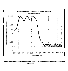
[0019] FIGURE 3 is a schematic diagram of the performance of the
NVIS-
compatible display of Figure 2, depicting a shifted long-wavelength peak of a
photoluminescent NVIS-compatible spectral profile.
[0020] FIGURE 4 is a schematic diagram of the spectral response of
the NVIS-
compatible display of Figure 2.
[0021] TABLE 1 lists the NVIS radiance requirements and the
performance of a
prototype of the present invention.
DESCRIPTION OF EXAMPLE EMBODIMENTS
[0022] It is to be understood that this invention is not limited
to the specific
devices, methods, conditions, or parameters described and/or shown herein, and
that
the terminology used herein is for the purpose of describing particular
embodiments by
way of example only. Thus, the terminology is intended to be broadly construed
and is
not intended to be limiting of the claimed invention. For example, as used in
the
specification including the appended claims, the singular forms "a," "an," and
"one"
include the plural, the term "or" means "and/or," and reference to a
particular numerical
value includes at least that particular value, unless the context clearly
dictates
otherwise. In addition, any methods described herein are not intended to be
limited to
the sequence of steps described but can be carried out in other sequences,
unless
expressly stated otherwise herein.
[0023] As shown in Figure 2, the present invention comprises a
backlight 10 for
an LCD display and includes a blue LED light source, in this example an array
12 of
blue LED elements (14, 16, 18) positioned in a first layer 22. A
photoluminescent layer
24 is positioned generally adjacent the first layer 22 of blue LED elements
for converting
blue LED emissions 26 into tri-colored light 28 for use as a full-color light
source, the
photoluminescent layer 24 being adapted for minimizing emissions in the NVIS
sensitive
range.
4
CA 02808609 2013-03-08
. . .
[0024] Optionally, the tri-color light profiles 28 outputted by
the photoluminescent
layer 24 for use as a full-color light source each has a Gaussian energy
output
distribution, and the long-wavelength emission peak is selected to minimize
emissions
in the NVIS sensitive regions. In addition or in the alternative, the medium-
wavelength
emission peak can be selected to minimize emission in NVIS sensitive regions.
[0025] The photoluminescent material works with a blue backlight
which excites
the photoluminescent -layer, causing medium and long-wavelength emissions,
creating
a "tunable" white source, as illustrated in Figure 2. In this regard,
"tunable" does not
refer to an ability to tune the device like a radio dial after it is
constructed, but rather to
the ability to design the device to have a desired performance. Thus, the
"tuning" is
accomplished in the design phase, not during use. One approach to tuning the
long-
wavelength peak is illustrated in Figure 3.
[0026] Preferably, the three primary color sources comprise a
short-wavelength
(450nm center, 5 30nm FWHM) emission profile equivalent to pinkish-blue, a
medium-
wavelength (540nm center, 5 30nm FWHM) profile equivalent to yellowish-green
and a
long-wavelength (610nm center, 5 20nm FWHM) emission profile equivalent to
reddish-
orange (color definitions per Gage, et al., "Optoelectonics Application
Manual" 1st
edition, McGraw Hill, New York, 1977).
[0027] Such a photo-luminescent backlight offers several
advantages. First, blue
LEDs are both cheaper and more efficient than white and RGB LED sources.
Second,
the peak outputs from the tri-color photoluminescent backlight can be tuned to
match
the LCD's color filters, providing greater efficiency. Third, the narrow
profiles of the
emission peaks create display colors that are more distinct and more
saturated. In the
past such technologies have not been used for NVIS-sensitive
environments/applications, because prior art photoluminescent backlights
output
unwanted emissions in NVIS sensitive regions. The present invention avoids
such
problems by avoiding the creation of unwanted emissions in the NVIS wavelength
range, thereby also avoiding the need for supplemental filters to remove those
unwanted emissions.
CA 02808609 2013-03-08
[0028] Advantageously, the present approach uses light, not voltage, to
excite
the photoluminescent material 14, 16, 18. In this regard, the material is
operated in a
passive mode or manner.
[0029] Advantageously, this approach eliminates the need for expensive
NVIS
filtering, while at the same time minimizing emissions in the NVIS sensitive
region
(which can interfere with NVIS goggles). Also, this approach allows for the
use of
cheaper monochromatic (e.g., blue) LEDs as a base light source, while still
providing
full-color NVIS compatibility and compliance. Also, this approach can be used
to tune
the emission peaks from the photoluminescent layer to match certain color
filters in an
LCD display to improve color saturation. For example, this can produce display
colors
that are more intense and/or more distinct from other colors.
[0030] Optionally, the blue LED light source could be replaced with
another blue
light source. For example, one can use fluorescent light sources, including
hot cathode
fluorescent lamps (HCFL) and cold cathode fluorescent lamps (CCFL). Also, one
can
use Light-Emitting Diodes, including semiconductor light-emitting diodes
(LEDs),
organic light-emitting diodes (OLED), and polymer light-emitting diodes
(PLED). Also,
one can employ lasers, including laser diodes, or electroluminescent Quantum
Dot
Light-emitting Devices (QD-LEDs or QLEDs). Moreover, other prior art light
source
technologies can be used, such as electron stimulated (CRT, etc.),
incandescent
(conventional tungsten, halogen, etc.), high-intensity discharge (xenon arc,
etc.), and
others which could be adapted for this application to generate a higher or
equivalent
energy/lower wavelength output sufficient to create the desired emissions in
the
photoluminescent layer.
[0031] Advantageously, this approach can provide cheaper and better color
(the
colors can be more distinct with better saturation), while using less power.
The power
efficiency can be achieved, at least in part, due to avoiding creating
energies that have
to be subsequently filtered.
6
CA 02808609 2013-03-08
[0032]
Advantageously, an NVIS-compatible backlight assembly according to the
present invention allows an array of relatively inexpensive blue LEDs,
together with a
photoluminescent layer positioned adjacent the array of blue LEDs, to minimize
radiance in NVIS-sensitive spectral regions. The emitted tri-color light
output from the
photoluminescent layer can have Gaussian emission profiles with the long-
wavelength
emission peak tuned to minimize spectral emissions in the NVIS sensitive
regions,
enhancing NVIS compatibility. Also, advantageously, the spectral profile
emitted by the
photoluminescent layer is substantially independent of angle of incidence.
Furthermore,
the backlight assembly is NVIS-compatible without needing any thin-
film/dichroic-based
NVIS filters. Optionally, one can augment the arrangement with supplemental
NVIS
radiance filtering. Also, one can augment the arrangement with scattering
elements to
minimize any need for a diffusion layer.
Further, the peak outputs from the
photoluminescent layer can be tuned to match the LCD's color filters,
providing greater
efficiency. In addition, the photoluminescent layer can be supplemented with
standard
NVIS filtering schemes to further improve NVIS performance and pass stricter
NVIS
requirement levels. Optionally, the photoluminescent layer can be configured
to operate
as a filter, lens or other optical component.
[0033] The
inventions disclosed herein have several advantages over NVIS
filtering schemes:
1. Greater power efficiency is achieved by using more efficacious blue LEDs
and by avoiding the creation of energies that are subsequently filtered.
2. The ability of the photoluminescent layer to tune the location of the
emission
peaks that match an LCD's color filters.
3. The emission from the photoluminescent layer exhibits narrow profiles which
result in improved colors that are more distinct and have greater saturation.
4. The narrow Gaussian profile and tuning of the long-wavelength emission
peak allows the display configuration to achieve NVIS compatibility and
compliance while maintaining greater color gamut.
5. The photoluminescent layer's spectral profile remains fixed over a wide
angle
7
CA 02808609 2013-03-08
of incidence.
[0034] This approach also eliminates the need for expensive dichroic/thin-
film
and absorptive NVIS filters, while at the same time making use of cheaper
monochromatic blue LEDs.
[0035] A prototype display utilizing the above approach shows promising
results.
A blue LED backlight was mated with a photoluminescent layer deposited on a
polyester gel film as part of the backlight configuration for an LCD display.
The display
exhibits no blooming when observed through NVIS goggles and passes MIL-STD-
3009
Class-B spectral radiance performance requirements for multi-color displays,
as listed in
Table 1.
Table 1. NVIS Class-B Requirements and Performance of a Proposed Prototype
Backlight Solution
NVIS-compatible
NVIS-B Type I/II
Color Fields phtoluminescent backlight
Requirement
performance
White 2.1E-09 2.2E-09
Max
1.0E-08 1.1E-08
[0036] While the invention has been shown and described in exemplary
forms, it
will be apparent to those skilled in the art that many modifications,
additions, and
deletions can be made therein without departing from the spirit and scope of
the
invention as defined by the following claims. For example:
a. The photoluminescent layer may be supplemented with standard NVIS
filtering schemes to further improve NVIS performance and achieve
stricter NVIS requirement levels.
b. The photoluminescent layer approach may be applied to monochrome
displays and additional NVIS-Class standards and requirements.
8
CA 02808609 2013-03-08
. . = .
c. The photoluminescent layer may be configured to operate as a filter, lens
or other optical component.
d. The photoluminescent layer may include scattering elements to avoid or
lessen the need for a diffusion layer.
[0037] These and other modifications, additions, and deletions are
within the
spirit and scope of the invention as defined by the following claims.
9