Note: Descriptions are shown in the official language in which they were submitted.
CA 02809806 2015-03-30
TURN COLLAR FULCRUM HANDLE SYSTEM
PRIORITY
[0001] This application claims priority from US Provisional Patent
Application
No. 61/625,566, filed April 17, 2012.
FIELD
1 0 [0002] This invention relates generally to detachable
auxiliary handles for use
with long shaft implements such as shovels, rakes, pitchforks, brooms, etc.
BACKGROUND
1 5 [0003] Snow shoveling can be an especially painful experience
due to low
back disc compression from repeated bending and lifting of heavy snow loads
(the
average shovelful of snow weighs 15-25 pounds). Each year over 100,000 people
in
North America end up in emergency rooms, clinics and doctors' offices due to
injuries
related to snow shoveling; sadly over 100 people suffer cardiac arrest and
die. The
20 shovel is ubiquitous, yet its design has remained relatively unchanged
for thousands
of years. The majority of households in North America have at least one long
shaft
tool that, due to design, will cause some level of back strain due to
inappropriate
bending or excessive spinal loading.
[0004] Accordingly, the applicants have recognized a need for
improved
25 systems and methods for facilitating the use of various implements.
- 1 -
CA 02809806 2013-03-18
=
BRIEF SUMMARY OF THE INVENTION
[0005] The Turn Collar Fulcrum Handle System described herein may
provide
a single light weight fulcrum handle with no moving parts, complicated
assembly or
tools required to releasably attach it to long shaft tools. The Turn Collar
Fulcrum
Handle is a simple click on/click off design that may be moved from one tool
to
another tool. The Turn Collar Fulcrum Handle can be placed adjacent to the
load
(e.g. a shovel full of snow), thereby reducing the lifting effort which may be
required
and which may also reduce the need for the user to bend.
1 0 [0006] Light weight versions of the Turn Collar Fulcrum Handle may
be used
for brooms, mops, rakes, etc., while a heavy duty J-hook turn collar
configuration
may be used for lifting heavier loads that require optimal ergonomic support,
while a
version with a shorter or no fulcrum arm can attach to long shaft tools that
did not
come with an end handle by attaching with the unique locking turn collar. In
1 5 summary, an easily repositionable turn collar fulcrum handle will
ensure continued
use when and where it is needed in order to provide optimal ergonomics and
safe
lifting when using long shaft tools to lift loads that can cause pain, fatigue
and
repetitive stress or back injuries.
[0007] The described embodiments relate to auxiliary or fulcrum
handles which
20 may be releasably coupled to tools and other implements.
[0008] In one broad aspect, there is provided a handle for use
with and/or for
releasably coupling to an implement. The handle may include: a handgrip, an
arm
operatively coupled to the handgrip, and a collar operatively coupled to the
arm
remote from the handgrip. The collar may be configured to releasably receive a
shaft
25 of the implement. The collar may comprise two substantially opposing
collar portions
defining a shaft pathway, wherein the collar portions are displaced axially
along the
shaft pathway to form a keyway sized to receive the shaft when the shaft and
the
shaft pathway are substantially orthogonal to each other.
- 2 -
CA 02809806 2013-03-18
[0009] In some instances, the collar portions may be curvilinear. As
well, in
some implementations, the handle may include a support portion, wherein the
shaft
pathway is intermediate or between the support portion and the handgrip.
[0010] In some embodiments, the collar comprises a reinforced spine.
The
shaft pathway may be positioned between the spine and the handgrip.
[0011] The collar may include a support and the shaft pathway may be
positioned between the support and the handgrip.
[0012] In some instances, the collar may comprise a J-hook
configuration.
[0013] A sizing insert may be provided which is configured to seat
within the
1 0 collar. The collar may be configured to receive a sizing insert. In
some such
implementations, the sizing insert may comprise a nub and wherein the collar
comprises a dimple configured to receive the nub.
[0014] For some embodiments, the arm may be configured for
telescopic
extension.
1 5 [0015] Another broad aspect may be directed towards a set of
handles for
simultaneous use with an implement. Each handle in the set may comprise: a
handgrip, an arm operatively coupled to the handgrip, and a collar operatively
coupled to the arm remote from the handgrip and configured to releasably
receive a
shaft of the implement. The collar may include: two substantially opposing
collar
20 portions defining a shaft pathway, wherein the collar portions are
displaced axially
along the shaft pathway to form a keyway sized to receive the shaft when the
shaft
and the shaft pathway are substantially orthogonal to each other. The set may
comprise a first handle and a second handle, and the arm of the first handle
is of a
different length than the arm of the second handle.
25 [0016] In some implementations, the collar portions may be
curvilinear.
[0017] One or both of the first and second handles may comprise a
support
portion, wherein the shaft pathway is intermediate the support portion and the
handgrip.
- 3 -
CA 02809806 2013-03-18
= .
[0018] In some instances, one or both of the first and second
handles may be
configured such that the collar comprises a reinforced spine. In such a
configuration,
the shaft pathway may be positioned between the support and the handgrip.
[0019] In some implementations, for at least one handle in the
set, the collar
comprises a J-hook configuration.
[0020] The set may also include a sizing insert configured to seat
within the
collar of at least one handle in the set. In some instances, the collar of at
least one
handle in the set is configured to receive a sizing insert. The sizing insert
may
comprise a nub and the collar of the at least one handle in the set may
comprise a
dimple configured to receive the nub.
[0021] For some embodiments, the arm of at least one handle in the
set may
be configured for telescopic extension.
[0022] These and other aspects and features of various embodiments
will be
described in greater detail below, with reference to the figures in which like
numbers
1 5 correspond to like references throughout.
DRAWINGS
[0023] Embodiments are described in further detail below, by way
of example
only, with reference to the accompanying drawings, in which:
[0024] Fig. 1 shows a Front Isometric view of a Turn Collar Fulcrum Handle
according to one aspect, mounted on the shaft of a representative implement in
the
form of a shovel.
[0025] Fig. 2a shows a Top view of the Handle of Fig. I.
[0026] Fig. 2b shows a Bottom view of the Handle of Fig. 1.
[0027] Fig. 3a shows a Right Side view of the Handle of Fig. 1.
[0028] Fig. 3b shows a Left Side view of the Handle of Fig. I.
- 4 -
CA 02809806 2013-03-18
..
[0029] Fig. 4a shows a Front Isometric view of the Handle of Fig.
1 as viewed
down the bore/shaft pathway of its Turn Collar.
[0030] Fig. 4b shows a Rear Isometric view of the Handle of Fig. 1
as viewed
down the bore/shaft pathway of its Turn Collar.
[0031] Fig. 5a shows a Bottom Isometric view of the Handle of Fig. 1 as it
first
fits onto an implement Shaft, prior to turning.
[0032] Fig. 5b shows a Bottom Isometric view of the Handle of Fig.
1 as it is
locked onto an implement Shaft.
[0033] Fig. 6a shows a Side schematic illustration of a user
lifting a load by the
1 0 conventional means.
[0034] Fig. 6b shows a Side schematic illustration of a user
lifting a load with
the Handle of Fig. 1 attached to the shaft of an implement.
[0035] Fig. 7a shows Side views of a sizing Insert and a first
alternate
embodiment of a Turn Collar Handle configured to receive the sizing Insert.
[0036] Fig. 7b shows enlarged views of a cross section of the Left Collar
portion of the Handle of Fig.7a and how the Insert engages its walls.
[0037] Fig. 8a shows a Rear Isometric view of a second alternate
embodiment
(J-Hook configuration) of a Turn Collar Handle employing a replaceable Turn
Collar.
[0038] Fig. 8b shows a Front Isometric view and Fig. 8c shows a
Left Side
Isometric view of the Handle of Fig. 8a.
[0039] Fig. 9a shows a Front Isometric view of a set of Handles
corresponding
to the Handle in Fig. 1. The Handle attached to the distal end of the
implement shaft
is shorter than the Handle proximate the front of the implement (illustrated
in dotted
outline as a shovel).
[0040] Fig. 9b shows a front isometric view of a third alternate embodiment
of
a Turn Collar Handle.
[0041] Fig. 9c shows a Side view of the Handle of Fig. 9b.
- 5 -
CA 02809806 2013-03-18
DETAILED DESCRIPTION
[0042] All elements will now be introduced by reference to drawing
figures,
then how each element functions and interacts with each other element will be
described in more detail when necessary. For sake of brevity in this
disclosure, the
Turn Collar Fulcrum Handle System may also be referred to herein as the TCF
Handle or handle or Handle.
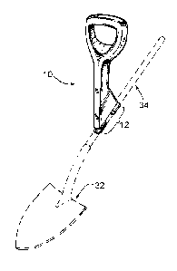
[0043] Fig. 1 shows a front isometric view of a first embodiment of
the TCF
1 0 Handle, shown generally as 10, releasably coupled or mounted by means
of its turn
collar 12 onto the shaft 34 of a representative implement 32 (illustrated in
this
example as a generic shovel).
[0044] Fig. 2a shows a top view of the TCF Handle 10 with its turn
collar 12, a
fulcrum arm 54, and a handle portion 26 with its yoke 28 and handgrip 30. As
will be
1 5 understood, the arm 54 is mounted to, comolded together with, or
otherwise
operatively coupled to the handgrip 30. Correspondingly, the collar 12 is
operatively
coupled to the arm 54, remote from the handgrip. Fig. 2b shows a bottom view
of the
TCF Handle 10 exposing elements of the turn collar 12, namely its left collar
portion
14, right collar portion 16, spine 20 and keyway 22.
20 [0045] Fig. 3a shows a right side view of a TCF Handle 10, with
the gusset 24
sides of the fulcrum arm 54, and highlighting how both collar portions have a
bevel
18 as shown in the keyway 22. Fig. 3b shows the left side view of the TCF
Handle
10. The gusset 24 reinforces the structural integrity of the TCF handle 10.
[0046] Fig. 4a shows a front view of a TCF Handle 10 as viewed down
the
25 bore or shaft pathway of its turn collar 12. This view also illustrates
the curvilinear
nature of the collar portions, 14, 16, forming a substantially cylindrical
shaft pathway
in this embodiment. However, it should be understood that the shaft pathway
does
not need to be strictly cylindrical and that other shapes and configurations
may be
utilized as appropriate. Fig. 4b shows a rear view of a TCF Handle 10 as
viewed
30 down the bore or shaft pathway of its turn collar 12.
- 6 -
CA 02809806 2013-03-18
[0047] Fig. 5a shows a bottom view of the TCF Handle 10 as an
implement
shaft 34 fits onto its keyway 22, prior to turning. Fig. 5b shows a bottom
view of the
TCF Handle 10 as its turn collar 12 is secured to the implement Shaft 34.
[0048] Fig. 6a shows a side view of schematic "stick figure" illustration
of a
User 36 lifting a load 38 on the end of a shaft 34 by conventional means. Fig.
6b
shows a side view of a User 36 lifting a load 38 with a TCF Handle 10 attached
or
coupled to the shaft 34 of an implement. Note the angle of the user's 36 lower
back
40 in each figure. Use of the embodiments of the handle described herein may
1 0 improve a user's 36 posture and thereby help prevent associated load
bearing back
injuries.
[0049] Fig. 7a shows side views of a sizing Insert 42 configured to
securely fit
into or seat within a collar 12' of a first alternate embodiment of a handle
shown
generally as 10' by means of corresponding one or more nubs 44 and one or more
1 5 dimples 46. Fig. 7b shows enlarged views of a cross section of a Left
Collar 14' and
how the Insert 42 engages its walls by means of each dimple 46 configured to
receive a corresponding nub 44. As will be understood, the collar 12' and
correspondingly each collar portion 14', 16' is configured to receive the
sizing insert
42. The use of a sizing insert 42 enables the reduction of the diameter of the
shaft
20 pathway, for use with implements having a smaller diameter than the
shaft pathway
of the collar 12'. As will be understood, the thickness and interior
configuration of the
sizing insert 42 may be determined for different applications, and for
example, may
be determined for use with a specific implement (and in particular the size
and
configuration of the shaft of such implement). As will also be understood, a
set or
25 other plurality of sizing inserts may be provided, each having a
different internal shaft
pathway sizing and/or configuration.
[0050] Fig. 8a shows a rear isometric view of a second alternate
embodiment
of the TCF Handle shown generally as 10" employing an interchangeable turn
collar
(having a J-hook configuration) 12" having collar portions 14", 16" and a
reinforced
30 spine 20" which slides into the slot 62 at the top of the stage 60 which
forms the
- 7 -
CA 02809806 2013-03-18
=
lower part of the J-Hook 58. As will be understood, the shaft pathway formed
by the
collar portions 14", 16" is intermediate or positioned between the spine 20"
and the
handgrip 30". A tubular fulcrum arm 54" is secured into the hook sleeve 56 and
then
handle sleeve 50 by means of fasteners 52. Note that in various portions of
the
design of the handle portion 26" and J-Hook assembly 58, coring 48 is present
to
lighten the structure and permit easy removal from plastic molds. Coring 48
can also
be used to create better a gripping surface as seen on the handgrip 30". Fig.
8b
shows a front isometric view of the same embodiment 10" and reveals how the
turn
collar 12" slides into the slot 62 of the stage or support portion 60 that
forms part of
1 0 the J-Hook 58, and its fastener 52. As will be understood, the shaft
pathway formed
by the collar portions 14", 16" is intermediate or positioned between the
support 60
and the handgrip 30".
[0051] Fig. 8c shows a left side isometric view of the second
alternate
embodiment 10".
1 5 [0052] Fig. 9a shows a Front Isometric view of a set (shown
generally as 100)
of a plurality (typically two) handles, a first handle 10A and a second handle
10B, the
respective arms 54A, 54B of which are of different lengths. In the illustrated
example, the arm 54B of the second handle 10B, attached to the distal end of
the
implement shaft 34 (remote from the load being carried at the head of the
shovel 32)
20 is shorter than the arm 54A of the first handle 10A. As will be
understood, each
handle in the set 100 may comprise various combinations of features and
configurations as contemplated herein. Furthermore, each handle in the set 100
need not (but may) share the same general configuration as every other handle
in
the set 100. For example, a first handle might comprise a J-hook configuration
for
25 improved weight bearing, while a second handle in the set 100 might
comprise the
configuration illustrated in Fig. 1.
[0053] Fig. 9b shows a Front Isometric view of a third alternate
embodiment of
a handle 10" with handle portion 26" and arm 54". Fig. 9c shows a Side view of
the
handle 10".
- 8 -
CA 02809806 2013-03-18
[0054] For consistency of understanding, the following key terms
will be
explained, namely turn collar, implement, keyway, collar half and fulcrum
handle.
[0055] In general terms, a Turn Collar, may be understood to
comprise a tube
or pathway (sometimes referred to herein as a "shaft pathway") defined by two
substantially opposing and substantially rigid collar halves or portions
connected by a
spine with a central keyway the width of an implement shaft. The collar
portions may
be displaced axially along the shaft pathway, thereby forming the keyway
between
them. As will be understood, the keyway is configured or sized to receive a
shaft of
an implement when the shaft is substantially orthogonal to the shaft pathway.
When
an implement shaft is placed in the keyway of a turn collar, and the latter is
turned 90
degrees, the shaft can be locked securely within the turn collar halves. Note:
when
the shaft engages the beveled edges of the collar halves, they are levered
outwards
momentarily so that when the shaft is fully seated within the turn collar, the
collar
halves or portions grip the shaft securely, restricting handle movement up or
down
the shaft, side to side handle movement, and the inadvertent and potentially
dangerous release of the fulcrum handle from the shaft when loaded.
[0056] As used herein, an Implement will generally be understood to
refer to a
tool having a shaft. The shaft of such a tool may be lengthy (but is not
necessarily
required to be) and may in some instances be used to lift, push, dig, lever,
pull, or
otherwise manipulate loads at a distance. By way of example only and without
limitation, implements may include rakes, spades or shovels, brooms,
pitchforks,
thatchers, snow shovels, paint rollers, hoes, trowels, and hand gardening
tools.
[0057] As will be generally understood, as used herein, a Keyway may
be in
the form of an aperture in the center of turn collar where the shaft of an
implement is
inserted at an ergonomically appropriate position for use of the handle
described
herein. Turning either the turn collar or the shaft within the keyway so that
opposing
collar halves lock the shaft within the turn collar, the fulcrum handle is
then secured
to the shaft of an implement.
[0058] As used herein, a Collar Half or portion (sometimes referred
to as a Left
Collar and Right Collar as seen from user's position above the implement shaft
with a
- 9 -
CA 02809806 2013-03-18
=
TCF Handle installed) will generally be understood to refer to each half or
segment of
a turn collar which together with the spine enclose and secure the attached
handle to
a (typically cylindrical) implement shaft.
[0059] A fulcrum is the support about which a lever pivots, and in
the case of a
long shaft implement is the point between the user's hands gripping the shaft.
By the
addition of a fulcrum handle (as described in this disclosure) on the
implement shaft,
the fulcrum point is raised to a more ergonomic position, and (as illustrated
in Figs.
6a & 6b) reducing the risk to the user's lower back.
[0060] Some of the unique attributes and functionalities of the
Turn Collar
Fulcrum Handle System 10 as illustrated in this disclosure are facilitated by
the
simple and versatile turn collar 12 design. The turn collar 12 permits easy
yet secure
repositioning of a fulcrum handle without the need for any secondary
attachment
means or tools required. By this means, long shaft implements can be used in a
safer
and more ergonomic manner. As shown in Figs. 5a & 5b, a shaft 34 is inserted
into
1 5 the keyway 22 gap between the left collar 14 and the right collar 16.
In order for the
opposing collars to securely lock the fulcrum handle onto the implement shaft,
the
internal diameter of the turn collar should preferably match or be slightly
smaller than
the diameter of the implement shaft. By this means the turn collar may be
locked onto
the shaft with sufficient force to secure the fulcrum handle in place. Size of
the
keyway 22, bevels 18 and the amount overlap of collar halves also determine
how
much force is required to both open the turn collar and to permit optimal
securing of
the handle on the shaft. When a turn collar is tailored to meet these
requirements, the
outcome is a fulcrum handle which may be disengaged from an implement shaft by
a
90 degree rotation, and then re-engaged in a different position on the same
shaft, or
attached to a different implement shaft with a similar diameter.
[0061] While there is some uniformity to common long tool shaft
diameters,
often 1.25 inches, not all long tool shafts are the same. As shown in Figs. 7a
& 7b, an
insert 42 may be used to offer more versatility in the size of shafts for
which the TCF
Handle 10 can attach. In this implementation, nubs 44 on the outside of the
insert 42
fit into dimples 46 in the inside of the halves of the turn collar 12. Other
insert 42
-10-
CA 02809806 2013-03-18
fastening solutions may be employed towards similar ends. Interchangeable turn
collars 12 fitting different shaft diameters will be discussed in the J-Hook
embodiment
below.
[0062] Alternate embodiments of the Turn Collar Fulcrum Handle
System 10
will now be discussed. Other embodiments are not ruled out or similar methods
leading to the same result.
[0063] J-Hook Embodiment:
[0064] While the embodiment illustrated and described in relation to
Fig. 1
may be used to control both light and heavily loaded implements, in the latter
case
1 0 there is a higher risk of a loaded shaft pushing through a downward
facing turn collar
if the collar is not made from strong enough material. To reduce the risk of
unintended detachment, a J-Hook 58 TCF Handle 10" employs an upwards facing
turn collar 12", as shown in Figs. 8a-8c. The interchangeable turn collar 12"
slides
into a slot 62 and is secured by a fastener 52 into a supporting stage 60
which forms
1 5 part of the J-Hook 58 configuration. A hook sleeve 56 receives a
fulcrum arm 54
which receives the handle portion 26 at its handle sleeve 50. By this means,
the J-
hook 58 embodiment supports the implement shaft 34 along the spine 20 of the J-
hook configuration turn collar 12" and this is carried by the stage 60.
Similar
functionality is available as with the embodiment illustrated and described in
relation
20 to Fig. 1, and also includes the option of selecting from
removable/releasably
mountable turn collars 12" with different internal diameters for implement
shafts of
different diameters. Note that the fulcrum arm 54 as shown in Figs. 8a-8c may
also
be constructed so as to be capable of telescopic extension in a fashion
similar to
walking canes with a sprung button through a series of holes. By this means,
the J-
25 Hook 58 TCF Handle 10 can provide an even broader range of ergonomic
options.
[0065] Short Handle Embodiment:
[0066] As shown in Fig. 9a, a short handle 10B is a TCF Handle with
a very
short or non existent fulcrum arm 54B. A short handle 10B could attach to an
implement shaft mid-way for lighter applications like light a rake. As shown
in Fig. 9a,
30 it could also be used in a set 100 at the distal end of long shaft tools
that don't have a
-11 -
CA 02809806 2013-03-18
=
D' shaped handgrip, like a rake or spade. A short handle 10B allows the top
hand to
grip the implement in a more ergonomically correct position.
[0067] Extension Handle Embodiment:
[0068] As shown in Figs. 9b & 9c, an extension handle 10" is a TCF
Handle
where a short extension from the turn collar 12 orients the handle in line and
extended away from the implement shaft 34. For example, a shovel without an
end
handgrip can be extended by connecting an extension handle 10"' to its distal
end by
its locking turn collar 12. By this means the tool can be used with more
control and
safety.
1 0 [0069] Materials used for constructing a turn collar fulcrum handle
may depend
on the loading expected on the implement shaft, as well as the environment in
which
the TCF Handle will be used. Hence the gusseted or the J-hook versions may be
completely formed from injection molded plastics, but a high wear component
such
as the turn collar may be made from more durable plastic compounds, carbon
fiber,
metal, or similar more resilient materials.
[0070] Other advantages of using the turn collar fulcrum handle
over other
methods or devices will now be discussed. The TCF Handle system may enhance
and improve the use of most long shaft implements by providing ergonomic use,
improved safety, reduced pain and fatigue and range of motion capabilities.
The TCF
Handle may be used with push brooms where the handle extends reach of arms
without requiring the user to bend over to create force on surface to scrub
away
debris. The same principle enables one to use a snow shovel with greater
control and
ergonomic efficiency. While lighter implements may not carry the same loads as
shovels, etc., they do generate repetitive stress injuries if not used
properly. The TCF
Handle may improve the use of brooms, mops, rakes, and other implements that
can
cause injury with overuse. Another application of the TCF Handle system may
permit
the use of a long shaft tool when a person has an existing back injury. If
such person
is unable to freely bend forward, or cannot bend their legs, use of a TCF
Handle may
facilitate the use the long shaft tool. The various disclosed embodiments may
allow
for different loading applications and may also provide an ergonomic fulcrum
handle.
-12-
CA 02809806 2013-03-18
The disclosed embodiments may also provide the ability to easily reposition
the
handle at different points along a tool shaft or onto a different tool without
secondary
attachment means.
[0071] The foregoing description of the preferred apparatus and method
of
installation should be considered as illustrative, and not limiting. Other
forming
techniques and other materials may be employed towards similar ends. Various
changes and modifications will occur to those skilled in the art, without
departing from
the true scope of the invention as defined in the present disclosure.
- 1 3 -