Note: Descriptions are shown in the official language in which they were submitted.
WO 2012/027779 CA 02809878 2013-02-281
PCT/AU2011/001095
OPTICALLY VARIABLE DEVICE
FIELD OF THE INVENTION
The present invention relates to optically variable devices for security and
decorative purposes, and methods of their manufacture.
BACKGROUND OF THE INVENTION
It is known to provide optically variable devices in which arrays of
lenticular
(part-cylindrical lenses) focus on an object plane containing multiple sets of
interleaved image elements. Each set of image elements (strips) belongs to a
distinct image, so that as the person viewing the device changes the angle of
view, a different image becomes visible.
In security applications, and in particular when dealing with flexible
security
documents such as banknotes, it is desirable to minimise the thickness of a
lens
array applied to the security document. For example, a preferred thickness for
polymer banknote substrates currently in use is approximately 90 microns,
including the thickness of the lens array. In order to meet this design
constraint,
lenses of diameter approximately 50 microns or less are used.
The effect produced by optically variable devices containing multiple sets
of interleaved image elements as described above is sometimes known as a
"flipping image" effect. The number of distinct images in the flipping image
effect
is limited by the number of sets of image elements that can be placed in the
field
of view of a lens in the lens array. For example, if a two-channel flipping
image is
to be produced, then two sets of image elements are required. This means that
each image element can have a width no greater than half the width of a lens.
If lenses of width 50 microns are used, the image elements should be no
greater than 25 microns wide in order to ensure that there is minimal cross-
talk
between the channels of the flipping image. An image element width of 25
microns or less is achievable with some techniques used in security printing.
However, other commonly used techniques, such as gravure (sometimes known
as rotogravure) printing cannot consistently apply image elements having this
width. A minimum practical width of line elements currently achievable with
gravure printing is approximately 35-45 microns. Image elements of this width
produce unacceptably large amounts of cross-talk when used with 50 micron
diameter lenses.
WO 2012/027779 CA 02809878 2013-02-282
PCT/AU2011/001095
It has previously been found that a given substrate thickness can be
maintained, whilst increasing the diameter of the lenses in the lenticular
array, by
adjusting the lens parameters such that the focal point width of the lenses in
the
object plane is approximately the same as the width of the image elements, as
described in our PCT application PCT/AU2010/000243, incorporated herein by
reference in its entirety. For example, for a substrate thickness of 90
microns,
lenses of diameter 63.5 microns can be used. However, even with lenses of this
increased diameter, a flipping image device with two channels still produces
unacceptable cross-talk because the minimum practically achievable width of
gravure line elements is 35-45 microns, which is still more than half the lens
diameter.
There is therefore a need for an optically variable device which can
produce flipping image effects, and which can be produced using a wider
variety
of security printing techniques, whilst being less susceptible to cross-talk.
DEFINITIONS
Focal point size H
As used herein, the term focal point size refers to the dimensions, usually
an effective diameter or width, of the geometrical distribution of points at
which
rays refracted through a lens intersect with an object plane at a particular
viewing
angle. The focal point size may be inferred from theoretical calculations, ray
tracing simulations, or from actual measurements.
Focal length f
In the present specification, focal length, when used in reference to a
microlens in a lens array, means the distance from the vertex of the microlens
to
the position of the focus given by locating the maximum of the power density
distribution when collimated radiation is incident from the lens side of the
array
(see T. Miyashita, "Standardization for microlenses and microlens arrays"
(2007)
Japanese Journal of Applied Physics 46, p 5391).
Gauge thickness t
The gauge thickness is the distance from the apex of a lenslet on one side
of the transparent or translucent material to the surface on the opposite side
of
the translucent material on which the image elements are provided which
substantially coincides with the object plane.
WO 2012/027779 CA 02809878 2013-02-283
PCT/AU2011/001095
Lens frequency and pitch
The lens frequency of a lens array is the number of lenslets in a given
distance across the surface of the lens array. The pitch is the distance from
the
apex of one lenslet to the apex of the adjacent lenslet. In a uniform lens
array, the
pitch has an inverse relationship to the lens frequency.
Lens width W
The width of a lenslet in a microlens array is the distance from one edge of
the lenslet to the opposite edge of the lenslet. In a lens array with
hemispherical
or semi-cylindrical lenslets, the width will be equal to the diameter of the
lenslets.
Radius of curvature R
The radius of curvature of a lenslet is the distance from a point on the
surface of the lens to a point at which the normal to the lens surface
intersects a
line extending perpendicularly through the apex of the lenslet (the lens
axis).
Sag height s
The sag height or surface sag s of a lenslet is the distance from the apex
to a point on the axis intersected by the shortest line from the edge of a
lenslet
extending perpendicularly through the axis.
Refractive index n
The refractive index of a medium n is the ratio of the speed of light in
vacuo to the speed of light in the medium. The refractive index n of a lens
determines the amount by which light rays reaching the lens surface will be
refracted, according to Snell's law:
ni * Sin (a) = n * Sin (0 ) ,
where a is the angle between an incident ray and the normal at the point of
incidence at the lens surface, 0 is the angle between the refracted ray and
the
normal at the point of incidence, and n1 is the refractive index of air (as an
approximation n1 may be taken to be 1).
Conic constant P
The conic constant P is a quantity describing conic sections, and is used in
geometric optics to specify spherical (P = 1), elliptical (0 < P < 1, or P >
1),
parabolic (P = 0), and hyperbolic (P <0) lens. Some references use the letter
K to
represent the conic constant. K is related to P via K. P ¨ 1.
Lobe Angle
WO 2012/027779 CA 02809878 2013-02-284
PCT/AU2011/001095
The lobe angle of a lens is the entire viewing angle formed by the lens.
Abbe number
The Abbe number of a transparent or translucent material is a measure of
the dispersion (variation of refractive index with wavelength) of the
material. An
appropriate choice of Abbe number for a lens can help to minimize chromatic
aberration.
Security document
As used herein, the term security document includes all types of
documents and tokens of value and identification documents including, but not
limited to the following: items of currency such as banknotes and coins,
credit
cards, cheques, passports, identity cards, securities and share certificates,
driver's licences, deeds of title, travel documents such as airline and train
tickets,
entrance cards and tickets, birth, death and marriage certificates, and
academic
transcripts.
Transparent Windows and Half Windows
As used herein the term window refers to a transparent or translucent area
in the security document compared to the substantially opaque region to which
printing is applied. The window may be fully transparent so that it allows the
transmission of light substantially unaffected, or it may be partly
transparent or
translucent partially allowing the transmission of light but without allowing
objects
to be seen clearly through the window area.
A window area may be formed in a polymeric security document which has
at least one layer of transparent polymeric material and one or more
opacifying
layers applied to at least one side of a transparent polymeric substrate, by
omitting least one opacifying layer in the region forming the window area. If
opacifying layers are applied to both sides of a transparent substrate a fully
transparent window may be formed by omitting the opacifying layers on both
sides of the transparent substrate in the window area.
A partly transparent or translucent area, hereinafter referred to as a "half-
window", may be formed in a polymeric security document which has opacifying
layers on both sides by omitting the opacifying layers on one side only of the
security document in the window area so that the "half-window" is not fully
CA 02809878 2013-02-28
WO 2012/027779 PCT/AU2011/001095
5
transparent, but allows some light to pass through without allowing objects to
be
viewed clearly through the half-window.
Alternatively, it is possible for the substrates to be formed from an
substantially opaque material, such as paper or fibrous material, with an
insert of
transparent plastics material inserted into a cut-out, or recess in the paper
or
fibrous substrate to form a transparent window or a translucent half-window
area.
Opacifying layers
One or more opacifying layers may be applied to a transparent substrate to
increase the opacity of the security document. An opacifying layer is such
that
LT < L0, where Lo is the amount of light incident on the document, and LT is
the amount of light transmitted through the document. An opacifying layer may
comprise any one or more of a variety of opacifying coatings. For example, the
opacifying coatings may comprise a pigment, such as titanium dioxide,
dispersed
within a binder or carrier of heat-activated cross-linkable polymeric
material.
Alternatively, a substrate of transparent plastic material could be sandwiched
between opacifying layers of paper or other partially or substantially opaque
material to which indicia may be subsequently printed or otherwise applied.
Zero-order diffraction grating
A zero-order diffraction grating is a surface-relief or buried microstructure
which produces light in only the zero diffraction order under illumination by
light of
a given wavelength.
Generally, such zero-order structures have a periodicity which is less than
the desired wavelength of incident light. For this reason, zero-order
diffraction
gratings are sometimes also known as sub-wavelength gratings.
Embossable Radiation Curable Ink
The term embossable radiation curable ink used herein refers to any ink,
lacquer or other coating which may be applied to the substrate in a printing
process, and which can be embossed while soft to form a relief structure and
cured by radiation to fix the embossed relief structure. The curing process
does
not take place before the radiation curable ink is embossed, but it is
possible for
the curing process to take place either after embossing or at substantially
the
same time as the embossing step. The radiation curable ink is preferably
curable
WO 2012/027779 CA 02809878 2013-02-286
PCT/AU2011/001095
by ultraviolet (UV) radiation. Alternatively, the radiation curable ink may be
cured
by other forms of radiation, such as electron beams or X-rays.
The radiation curable ink is preferably a transparent or translucent ink
formed from a clear resin material. Such a transparent or translucent ink is
particularly suitable for printing light-transmissive security elements such
as
numerical-type DOEs and lens structures.
In one particularly preferred embodiment, the transparent or translucent ink
preferably comprises an acrylic based UV curable clear embossable lacquer or
coating.
Such UV curable lacquers can be obtained from various manufacturers,
including Kingfisher Ink Limited, product ultraviolet type UVF-203 or similar.
Alternatively, the radiation curable embossable coatings may be based on other
compounds, eg nitro-cellulose.
The radiation curable inks and lacquers used in the invention have been
found to be particularly suitable for embossing microstructures, including
diffractive structures such as DOEs, diffraction gratings and holograms, and
microlenses and lens arrays. However, they may also be embossed with larger
relief structures, such as non-diffractive optically variable devices.
The ink is preferably embossed and cured by ultraviolet (UV) radiation at
substantially the same time. In a particularly preferred embodiment, the
radiation
curable ink is applied and embossed at substantially the same time in a
Gravure
printing process.
Preferably, in order to be suitable for Gravure printing, the radiation
curable ink has a viscosity falling substantially in the range from about 20
to about
175 centipoise, and more preferably from about 30 to about 150 centipoise. The
viscosity may be determined by measuring the time to drain the lacquer from a
Zahn Cup #2. A sample which drains in 20 seconds has a viscosity of 30
centipoise, and a sample which drains in 63 seconds has a viscosity of 150
centipoise.
With some polymeric substrates, it may be necessary to apply an
intermediate layer to the substrate before the radiation curable ink is
applied to
improve the adhesion of the embossed structure formed by the ink to the
substrate. The intermediate layer preferably comprises a primer layer, and
more
WO 2012/027779 CA 02809878 2013-02-287
PCT/AU2011/001095
preferably the primer layer includes a polyethylene imine. The primer layer
may
also include a cross-linker, for example a multi-functional isocyanate.
Examples
of other primers suitable for use in the invention include: hydroxyl
terminated
polymers; hydroxyl terminated polyester based co-polymers; cross-lined or
uncross-linked hydroxylated acrylates; polyurethanes; and UV curing anionic or
cationic acrylates. Examples of suitable cross-linkers
include: isocyanates;
polyaziridines; ziconium complexes; aluminium acetylacetone; melamines; and
carbodi-i m ides.
The type of primer may vary for different substrates and embossed ink
structures. Preferably, a primer is selected which does not substantially
affect the
optical properties of the embossed ink structure.
SUMMARY OF THE INVENTION
The present invention provides a security element, including:
a plurality of focusing elements,
a first group of image elements, and
a second group of image elements,
each image element being located in an object plane to be viewable
through a focusing element, and being located a distance from the focusing
element such that the focal point width of the focusing element in the object
plane
is substantially equal to the size of the image element or differs from the
size of
the image element by a predetermined amount,
wherein image elements of the first group are visible in a first range of
viewing angles and image elements of the second group are visible in a second
range of viewing angles, and
wherein a second image formed in the second range of viewing angles is a
contrast-inverted version of a first image formed in the first range of
viewing
angles.
Preferably, the predetermined amount by which the focal point width varies
from the size of the image elements is not more than 20% of the size of the
image
elements.
The present inventors have found that by using first and second images
which are contrast-inverted versions of each other, together with a slightly
off-
focus lens design, a recognisable optically variable effect in the form of a
flipping
WO 2012/027779 CA 02809878 2013-02-288
PCT/AU2011/001095
image can be produced despite the presence of some cross-talk. When the first
group of image elements is visible it forms a foreground region of the first
image.
Although some cross-talk from the second group of image elements is visible,
the
cross-talk is greatly reduced compared to a design using on-focus lenses,
because only part of the focal spot overlaps with the image elements of the
second group. This reduced cross-talk forms a uniform background for the first
image.
Preferably the image elements are a colour other than black. It has been
found in some cases that a flipping image effect produced by black image
elements can be mimicked by using a metallic ink. The use of colours other
than
black precludes the use of metallic inks for counterfeiting.
In one embodiment, the first group of image elements is a different colour
to the second group of image elements. The use of different colours further
increases the difficulty to the counterfeiter.
The image elements may have a size distribution or a spatial distribution
corresponding to the grey levels or brightness levels of an input
monochromatic
image. The input image may be a portrait or other image having a large degree
of information content.
Preferably, the image elements are printed image elements, for example
gravure-printed, offset-printed, screen-printed or flexographically-printed
elements. Alternatively, the image elements may be embossed image elements.
In one preferred embodiment, the focusing elements are on one side of a
transparent or translucent substrate. The image elements may be on the
opposite side of the transparent or translucent substrate.
The image elements are preferably line elements, but may be any other
suitable shape, for example dots or geometrical shapes.
In one embodiment, the focusing elements are refractive or diffractive part-
cylindrical lenses, or zone plates. Alternatively, the focusing elements may
be
refractive or diffractive part-spherical or polygonal-base micro lenses.
In another aspect of the present invention there is provided a method of
forming a security device, including the steps of:
providing a transparent or translucent substrate,
WO 2012/027779 CA 02809878 2013-02-289
PCT/AU2011/001095
applying a plurality of focusing elements to a first surface of the substrate,
and
applying a first group of image elements and a second group of image
elements to an image surface of the substrate, each image element being
located
in an object plane to be viewable through a focusing element, and being
located a
distance from the focusing element such that the focal point width of the
focusing
element in the object plane is substantially equal to the size of the image
element
or differs from the size of the image element by a predetermined amount,
whereby image elements of the first group are visible in a first range of
viewing angles and image elements of the second group are visible in a second
range of viewing angles, and
whereby a second image formed in the second range of viewing angles is
a contrast-inverted version of a first image formed in the first range of
viewing
angles.
The focusing elements may be applied by embossing, preferably by
embossing in a layer of embossable radiation-curable ink applied to the first
surface of the substrate.
Preferably, the image elements are applied by a printing method.
Preferred methods are gravure-printing, offset-printing, screen-printing or
flexographic-printing. The image elements may also be applied by embossing.
In a further aspect, the present invention provides a security document,
including a security element according to any one of the above embodiments, a
security device according to the second aspect of the invention, or a security
device manufactured according to any of the methods described above. In one
preferred embodiment, the security element or security device is located
within a
window or half-window region of the security document.
BRIEF DESCRIPTION OF THE DRAWINGS
Preferred embodiments of the invention will now be described, by way on
non-limiting example only, with reference to the accompanying drawings, in
which:
Figures 1(a) to 1(d) show a lenticular device of known type;
Figures 2(a) to 2(d) show a modified version of the lenticular device of
Figures 1(a) to 1(d);
WO 2012/027779 CA 02809878 2013-02-2810
PCT/AU2011/001095
Figure 3 shows a flipping image effect produced by one embodiment of the
present invention;
Figure 4 is a perspective view of part of a security element producing the
effect of Figure 3;
Figure 5 is a cross-section through the security element of Figure 4;
Figures 6 and 7 schematically depict a method of producing artwork for
another embodiment of the present invention; and
Figure 8 shows the effect generated by the embodiment of Figures 6 and
7.
DETAILED DESCRIPTION OF THE DRAWINGS
Referring initially to Figure 1, there is shown part of a lenticular device 10
of known design, having a plurality of focusing elements in the form of part-
cylindrical lenses 14. The device 10 includes a substrate 11 having an upper
surface 12 and a lower surface 13. The focusing elements 14 are applied to the
upper surface 12, and the lower surface 13 is an object plane carrying a first
group of image elements 16 and a second group of image elements 17. Image
elements 17 are shown slightly offset in the cross-sectional view of Figure
1(a) for
purposes of clarity.
The left-hand edges of neighbouring image elements 16 of the first group
are aligned with the left-hand edges of associated focusing elements 14
through
which the image elements 16 are to be viewed. The left-hand edges of image
elements 17 of the second group are aligned with the optical axes associated
of
focusing elements 14. Image elements 16 and 17 are in interleaved relationship
in the object plane 13 (Figure 1(d)) to form first and second channels of a
flipping
image.
Object plane 13 is placed substantially at the focal length of the focusing
elements 14. This results in a very narrow region 15 in the object plane over
which incoming rays are focused, much narrower than the width of image
elements 16, 17.
In Figure 1(a), the security element substrate 11 has a thickness of
approximately 75 microns. In order to keep the total security element
thickness to
less than 90 microns, the sag height of the lenses 14 is less than 15 microns,
and
the lens diameter is of the order of 45 to 50 microns. If image elements 16,
17 are
WO 2012/027779 CA 02809878 2013-02-2811
PCT/AU2011/001095
applied by gravure printing, their width will be larger than half the lens
diameter.
This results in a cross-talk region of viewing angles in which both image
elements
16 and image elements 17 are visible. In the cross-talk region, for example at
viewing angles which view positions 20 of the device (Figure 1(c)), the image
elements 16 and 17 are each spanned by the entire width of focal region 15,
resulting in identical apparent brightnesses 26 and 27 (Figure 1(b)) to the
viewer.
The ability to distinguish between images 36 (character '5') and 37 (character
'A')
is thus completely lost due to the cross-talk between the two groups of image
elements 16, 17.
The cross-talk of Figure 1 can be reduced by using off-focus lens designs
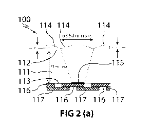
such as the one shown in Figure 2. In Figure 2(a), a lenticular device 100
includes focusing elements 114 applied to a first surface 112. The focusing
elements 114 have a focusing region 115 in the object plane 113 which is
almost
as wide as the image elements 116 of a first group and image elements 117 of a
second group. The focusing region may have a width which is up to 20% smaller
or 20% larger than the width of the image elements 116 or 117.
The use of a non-focusing design reduces cross-talk because in a cross-
talk region, a reduced portion of the focal region overlaps with an image
element
which is not intended to be seen by the viewer. For example, in region 120
shown
in Figure 2(c), image elements 116 of the first group should be visible to
display
the first channel of the flipping image, whilst image elements 117 of the
second
group should not be seen. The entire width of the focal region 115 overlaps
with
image elements 116 at the viewing angle shown in Figure 2(c), to produce an
apparent intensity 126 (Figure 2(b)). On the other hand, only part of image
element 117 overlaps with the focal region 115, so that a reduced intensity
127 is
seen by the viewer.
The net impression to the viewer emerging from the viewing angle shown
in Figure 2(d) is a first image 136 comprising a foreground region 126a in the
form of the character '5', produced by the first group of image elements 116.
Due
to the presence of cross-talk 128 from the second group of image elements 117,
a shadow 127a of character 'A' is seen in the background. As the device is
tilted,
character 'A' becomes more prominent, due to a greater proportion of the width
of
focusing region 115 viewing the image elements 117, and character '5' becomes
WO 2012/027779 CA 02809878 2013-02-2812
PCT/AU2011/001095
gradually more muted, until the two characters '5' and 'A' become
undistinguishable. On further tilting, the character 'A' dominates and forms
the
foreground 126b of an image 137, with the cross-talk 128 from image elements
116 of character '5' forming the background 127b.
Whilst the device 100 of Figure 2 gives an improved result compared to
device 10 of Figure 1, the amount of cross-talk between the two channels 126a,
126b of the flipping image may be unacceptably large for security document
applications. It has therefore been found greatly advantageous to select a
design
in which the two images of the flipping image are contrast-inverted versions
of
each other, as shown in the embodiment of Figures 3 to 5.
Referring to Figure 3, 4 and 5, there is shown a perspective view of part of
a security element 200 having a substrate 211 with upper surface 212 and lower
surface (object plane) 213. A first group of image elements 216 and a second
group of image elements 217, in the form of gravure-printed lines, are applied
to
lower surface 213. The image elements 216, 217 are viewable through
associated focusing elements (part-cylindrical lenses) 214 applied to the
upper
surface 212 of the substrate 211.
In the cross-sectional view of Figure 5, image elements 217 are slightly
offset from lower surface 213 for reasons of clarity. Image elements 217 of
the
first group are viewable in a first range of viewing angles from direction 230
to
direction 231, whilst image elements 216 of the second group are viewable in a
second range of viewing angles from direction 231 to direction 232. There is
also
a range of viewing angles from direction 231a to 231b, in which the whole of
cross-talk region 220 is seen by the viewer.
When the device 200 is viewed from angle 232, a first image 236 is visible,
in which the image elements 216 of the first group are brightest and produce
the
impression of a character '5'. Similarly, when the device 200 is viewed from
angle
230, a second image 237 is visible, in which the image elements 217 of the
first
group are brightest and produce the impression of a contrast-inverted
character
'5'.
In first image 236, first image elements 216 thus form the foreground
region 226a whilst second image elements 217 form a uniform background region
227a. Conversely, in second image 237, second image elements 217 form the
WO 2012/027779 CA 02809878 2013-02-2813
PCT/AU2011/001095
foreground region 226b whilst first image elements form a uniform background
region 227b. In each case, the cross-talk 228 becomes a uniform background to
the image 236, 237 which is desired to be projected.
Referring now to Figures 6 to 8, a method of producing a more complex
security element is depicted schematically.
In Figure 6, a monochromatic input image in the form of a portrait 300 is
shown. Portrait 300 is a greyscale bitmap having 256 grey levels. This is then
converted to a binary bitmap 302, for example by applying a frequency-
modulated
dithering, error diffusion, or random or stochastic screening. The result is a
two-
level (binary) bitmap which appears as a tonal portrait due to the spatial
distribution of the black pixels. A region with a higher spatial density of
black
pixels will tend to appear darker, whilst a sparser distribution will appear
lighter.
Figure 7 shows a close-up of one region 304 of the bitmap 302, a
subregion 306 of which is shown in further close-up. Region 306 includes black
pixellated regions 316a, 316b, 316c, 316d, and white pixellated regions 317a,
317b, 317c.
To produce a flipping image with contrast inversion, the black regions are
first mapped to a first group of image elements 321a, 321b, 321c and 321d
respectively, which are applied to security element 400 as a series of gravure-
printed lines with their left-hand edges substantially aligned with left-hand
edges
of lenses 314. The gravure-printed lines 321a-321d each have a length
corresponding to the length of the corresponding black pixellated region 316a-
316d.
The white pixellated regions are mapped to a second group of image
elements 322a, 322b and 322c respectively, which are applied to security
element 400 as a second series of gravure-printed lines with their right-hand
edges substantially aligned with right-hand edges of associated lenses 314.
Gravure-printed lines 322a-322c each have a length corresponding to the length
of the corresponding white pixellated region 317a-317c.
In a first range of viewing angles, a first image 336, substantially
reproducing the portrait 300, is seen by a person viewing the device 400
(Figure
8). This includes foreground region 326a from image elements 321a-321d, and
uniform background region 327a due to cross-talk from image elements 322a-
WO 2012/027779 CA 02809878 2013-02-2814
PCT/AU2011/001095
322c. As the device 400 is tilted through the first range of viewing angles,
the
amount of reflected light from background region 327a decreases, until the
viewer
reaches a second range of viewing angles in which background 327a begins to
dominate. In the second range of viewing angles, a second, contrast-inverted
image 337 is seen, in which image elements 322a-322c form the foreground
327b, whilst cross-talk from image elements 321a-321d forms the uniform
background 326b.
In a representative example of a method for manufacturing security
elements substantially as described above, a layer of embossable radiation
curable ink, for example UV-curable ink, is applied to one side of a 75 micron
thick biaxially oriented polypropylene (BOPP) film. The UV-curable ink is then
embossed with lens structures 214 or 314 and cured to produce a lenticular
substrate with a total thickness of approximately 85 to 90 microns.
The surface opposite the lens structures is gravure printed with image
elements 216, 217 (Figures 4 to 6) or 321a-321d, 322a-322c (Figure 7) of a
single colour. A preferred colour for the image elements is one which will
produce
sufficient contrast yet is difficult to imitate. Blue, magenta, violet or
scarlet are
preferred colours.
In a representative gravure printing process, a gravure cylinder engraved
with the resolution of 10,160 dpi (smallest incremental change in image
element
position of 2.5 microns) is used. The corresponding gravure engraving file is
a
binary digital image of the image elements, compensated for the anticipated
growth in size of the digital image elements after they are printed.
In order to design lenses of appropriate characteristics for the particular
substrate thickness being used, the lenses should have a focal point width
which
is substantially equal to the image element size, or differs from the image
element
size by a predetermined amount, preferably no more than 20%. A suitable
method is described in PCT application PCT/AU2010/000243, and includes a
measurement of the width of the image elements.
Measurement of the characteristics of the gravure-printed lines can be
accomplished using a variety of known methods. For example, the average line
width can be determined by printing a press calibration template consisting of
swatches of lines of a given size and having various densities, where each
CA 02809878 2013-02-28
WO 2012/027779
PCT/AU2011/001095
15
swatch typically represents a density value from one percent to ninety nine
percent. The template is subsequently imaged to film or plate, and printed
onto
the smooth side of an optical effect substrate. The printed result is then
scanned
using a densitometer, or similar tool, to determine the printed line width.
Alternatively, the average line width can be measured directly, for example
using a microscope fitted with a reticle displaying increments of measurement.
In
the direct method, a sample of lines can be measured in each tonal value
range,
recorded, and their sizes averaged.
In order to obtain lens parameters suitable for image elements of a given
width and a substrate of given thickness, the following relation between gauge
thickness t and lens parameters s (sag height), w (width), R (radius of
curvature),
P (the conic constant of the lens) and n (refractive index) is optimised:
t ¨ s + h¨ wA
(1)
with h being the measured half-width of a printed line, and A being given by
A = ¨Tan a(s)¨ ArcSin Sin(a(s))\-
n _ (2)
where
a(s)= ArcTan(3) 2 =
IR 2 ¨ P*w
The thickness t can be optimised with respect to one or more of the lens
parameters R, n, P, w and s in the usual way, ie by taking the partial
derivatives
of the expression in Eq (2) with respect to one or more of those parameters
and
setting the partial derivatives equal to zero. The resulting system of
equations can
be solved analytically or numerically in order to find the set of lens
parameters
which gives the optimal lens thickness.
The optimisation may be a constrained optimisation. For example, for
banknote substrates, it is desirable to limit t to a range of values between
about
85 microns and 100 microns. Constrained optimisation methods are known in the
art.
WO 2012/027779 CA 02809878 2013-02-2816
PCT/AU2011/001095
We have found that as long as the focal point size does not exceed the
average width of a printed halftone dot by more than 20%, the quality of the
image is not compromised. We have also found that simply producing an
arbitrary
non-focussing design severely degrades the image quality, resulting in an
objectionably blurred image. The focal point size may also be slightly smaller
than
the average width, preferably no more than 20% smaller.
Many variations of the above embodiments are possible without departing
from the spirit and scope of the present invention. For example, the security
elements described above may be manufactured separately, and then applied to
a security document, or may be applied to a security document in situ, for
example within a window or half-window region.