Note: Descriptions are shown in the official language in which they were submitted.
CA 02810147 2013-03-21
,
TITLE
,.
CONVERTIBLE TARP SYSTEM
BACKGROUND OF THE INVENTION
[0001]
This invention relates in general to convertible tarp systems, such as can be
used to create an enclosed cargo area on a flatbed trailer or the like. In
particular, this
invention relates to a convertible tarp system having improved guide tracks
and
corresponding trolley assemblies.
[0002] Flatbed trailers are often used to haul loads that are bulky or heavy.
These
loads often have handling characteristics that rely on access to the open
sides of the
trailer for loading and unloading. Flatbed trailers provide open access for
handling
freight but lack a structure for conveniently covering the loads from the
elements or
for privacy. Tarps are often used to protect freight carried on a flatbed.
Sometimes
the tarps are applied directly over the loads to guard against the elements.
Other
flatbed covers rely on bows and other support structures to create a space
over the
trailer and support one or more tarp sheets. While these structures cover the
flatbed
trailer and create an enclosed freight hauling space, the structures are
difficult or
cumbersome to remove in order to gain side access of the trailer for freight
handling.
Thus, it would be desirable to provide an improved tarp system for protecting
and
accessing freight.
SUMMARY OF THE INVENTION
[0003] This invention relates to a convertible tarp system having improved
guide
tracks and corresponding trolley assemblies.
[0004] In one embodiment, a convertible tarp system has a guide track and a
trolley
assembly. The guide track is configured to be secured to a trailer. The
trolley
assembly is supported for movement along the guide track. The trolley assembly
includes a pair of support rollers, an intermediate roller, and a pair of
guide rollers.
1
CA 02810147 2013-03-21
,
_
[0005] In another embodiment, a convertible tarp system includes at least one
bow
1
for supporting a tarp of a trailer. The tarp and bow cooperate to provide an
enclosure
for cargo. A guide track has a having a channel that defines a path of
movement of
the bow. A trolley has a pair of spaced apart support wheels that engage the
channel
and support the bow for longitudinal movement relative to the trailer. The
trolley also
has at least one guide wheel that supports the bow perpendicular to the path
of
movement.
[0006] In yet another embodiment, a covered trailering system has a
flatbed trailer
defining a deck space configured to accommodate cargo. A tarp structure covers
the
deck space and is supported by a plurality of bows that support a covering.
The
covering defines an enclosed cargo space having a variable volume. The
covering
may be a flexible tarp sheet of a plurality of generally rigid panels that are
arranged to
telescope from an extended position to a position wherein the enclosed volume
is
reduced. A guide track is secured to the flatbed trailer. The guide track has
a
longitudinally extending channel that includes an outer wall. A plurality of
trolleys
engage the guide track. Each trolley supports at least one of the plurality of
bows.
The trolleys have a plurality of support wheels and at least one guide wheel.
The
plurality of support wheels engage the channel for longitudinal movement
relative to
the trailer. The at least one guide wheel engages the outer wall of the guide
track for
lateral support of the bows relative to the trailer.
[0007] Various aspects of this invention will become apparent to those skilled
in
the art from the following detailed description of the preferred embodiment,
when
read in light of the accompanying drawings.
BRIEF DESCRIPTION OF THE DRAWINGS
[0008] Fig. 1 is a perspective view of a flatbed trailer with a
convertible tarp
system in accordance with this invention.
[0009] Fig. 2 is an enlarged perspective view of a portion of the flatbed
trailer and
convertible tarp system as shown in Fig. I.
2
CA 02810147 2013-03-21
,
_
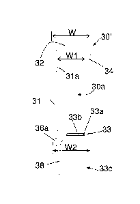
[0010] Fig. 3 is an enlarged perspective view of a portion of a guide track
shown in
a
Fig. 2.
[0011] Fig. 4A is an end view of the guide track shown in Fig. 3.
[0012] Fig. 4B is an end view of a second embodiment of a guide track, similar
to
the guide track of Fig. 4A.
[0013] Fig. 5 is an enlarged perspective view of a first embodiment of a rear
trolley
assembly shown in Fig. 2.
[0014] Fig. 6 is a front view of the rear trolley assembly shown in Fig. 5.
[0015] Fig. 7 is a perspective view of an outer side of the rear trolley
assembly
shown in Fig. 5.
[0016] Fig. 8 is an end view of the rear trolley assembly shown in Fig. 5.
[0017] Fig. 9 is an enlarged perspective view of an intermediate trolley
assembly
shown in Fig. 2.
[0018] Fig. 10 is a front view of the intermediate trolley assembly shown in
Fig. 9.
[0019] Fig. 11 is an end view of the intermediate trolley assembly shown in
Fig. 9.
[0020] Fig. 12 is an enlarged end view of a portion of the convertible tarp
system
shown in Fig. 2.
[0021] Fig. 13A is a second embodiment of a rear trolley assembly, similar to
the
rear trolley assembly of Fig. 5.
[0022] Fig. 13B is an exploded view of the rear trolley assembly of Fig. 13A
and a
back bow connection.
[0023] Fig. 14 is a second embodiment of an intermediate trolley assembly
similar
to the intermediate trolley assembly of Fig. 9.
3
CA 02810147 2013-03-21
DETAILED DESCRIPTION OF THE PREFERRED EMBODIMENT
[0024] Referring now to Figs. 1 and 2, there is illustrated a flatbed trailer
10 that is
partially covered with a convertible tarp system, indicated generally at 20.
The
illustrated convertible tarp system 20 includes a plurality of bows including
a front
bow 22, a plurality of intermediate bows 24, and a rear bow 26. A tarp section
28 can
be attached between the respective bows 22, 24, and 26 or, alternatively, a
single tarp
can be stretched along a length of the flatbed trailer 10. The ends of the
bows 22, 24,
and 26 are supported on a rolling track system that is provided on opposite
sides of the
flatbed trailer 10. Thus, the convertible tarp system 20 can be extended along
a deck
of the flatbed trailer 10 to create an enclosed cargo area or can be retracted
when not
in use. Although the convertible tarp system 20 is illustrated for use with a
flatbed
trailer 10, it should be appreciated that the tarp system 20 can be used in
any desired
environment and for any desired purpose. For example, in addition to the
trucking
industry, the convertible tarp system 20 may also be used in the rail and
shipping
industries or any other industry.
[0025] Words used herein to describe the relative orientation of components,
such
as upper, lower, left, right, vertical, horizontal, inner, outer, front, rear,
and the like are
intended to assist the reader in interpreting the drawings and structures
relative to how
they are illustrated and conventionally observed. Such descriptions are not
limited to
an absolute coordinate system, unless specifically defined herein, and are
merely
descriptive aids to describe and define the various embodiments disclosed
herein.
[0026] The illustrated convertible tarp system 20 includes a pair of guide
tracks 30
that respectively extend along opposite sides of the flatbed trailer 10. As
shown in
Figs. 4A and 4B, two embodiments of guide tracks 30 and 30' are described. The
same reference numbers are used to describe parts that are the same between
the two
embodiments. The guide tracks 30 and 30' can be secured to the sides of the
flatbed
trailer 10 in any manner. For example, the guide tracks 30 can be removably
supported on the flatbed trailer 10 using a plurality of threaded fasteners,
support
brackets, spacers, or any other support hardware. Alternatively, the guide
tracks 30
can be permanently secured to the flatbed trailer 10 using welded connections
or the
4
CA 02810147 2013-03-21
like. The illustrated guide tracks 30 are preferably similar to one another,
although
such is not required. Therefore, only one of the guide tracks 30 will be
described in
further detail.
[0027] Referring now to Figs. 3, 4A and 4B, the illustrated guide tracks 30
and 30'
include a vertical back wall 31. An upper wall 32 and a lower wall 33
horizontally
extend outwardly from the back wall 31 so as to generally overlap one another.
An
outer wall 34 vertically extends downwardly from the upper wall 32 and is
parallel
with the back wall 31. Thus, the back wall 31, the upper and lower walls 32
and 33,
and the outer wall 34 define a channel 30a having a C-shape configuration. It
should
be appreciated, however, that the guide track 30 can define a channel having
any
cross-sectional shape or configuration. As will be explained below, the C-
shaped
channel 30a opens away from the flatbed trailer 10 when the guide track 30 is
secured
thereto. The C-shaped channel provides a track that permits selective
longitudinal
movement of the assembled tarp structure and restricts lateral (side to side)
movement
of the tarp structure relative to the trailer.
[0028] The illustrated guide track 30 also includes a recessed portion 31a
that
extends along an inner surface of the back wall 31 near the upper wall 32,
although
such is not required. The recessed portion 31a increases the internal width W1
of the
channel between the back wall 31 and the outer wall 36 without increasing the
overall
width W of the guide track 30. The internal width W1 may provide clearance for
guide rollers, associated with the various trolley assembly embodiments
described
herein, for free movement of the trolleys within the guide track 30. This
permits use
of a larger guide wheels for added stability, durability, and reduced rolling
resistance.
The generally constant overall width W of the guide track 30 provides a
generally flat
surface of the back wall 31 for ease of mounting and leveling the guide track
30
relative to a side of the flat bed trailer 10. The lower wall 33 defines a
width W2 that
is less than the overall width W of the guide track 30. This smaller width W2
protects
the lower wall from impacts such as from fork lifts during loading and
unloading
events. Thus, the width difference between the lower wall, which supports the
support
CA 02810147 2013-03-21
wheels of the trolleys, and the outer dimension W of the guide track shields
the lower
wall from damage to permit smooth operation of the trolleys during tarp
movement.
[0029] Further, the illustrated lower wall 33 includes a groove 33a that
extends
along an upper surface thereof, although such is not required. The illustrated
groove
33a has a dove-tail shape, when viewed in cross section, but may alternatively
have
any other shape or configuration. The groove 33a is configured to accept and
retain a
wear strip 33b. In the illustrated embodiments of Figs. 3 and 4B, the wear
strip has a
mating dove-tail shape and may be a slip fit, press fit, or molded-in-place
fit with the
groove 33a. The wear strip 33b may be retained by friction, fasteners, tape,
adhesive,
and the like. The wear strip 33b provides a surface for guide rollers to ride
against
during movement of the bows 22, 24, and 26. The wear strip 33b may be made of
a
hard metal or plastic material for wear resistance, reduced friction and/or
corrosion
resistance. In one embodiment, the wear strip 33b is a removable polymer
strip,
configured for replacement when excessively worn.
[0030]
Referring to Fig. 4A, the illustrated guide track 30 may also include a light
bar 35. The illustrated light bar 35 extends along a bottom portion of the
guide track
30 and defines a housing-like structure having an opening along a back side
thereof.
The light bar 35 is configured to house lights, such as individual lights or a
string of
lights (not shown), along a length of the guide track 30. The light bar 35 is
not limited
to the illustrated structure but can be alternatively configured in any
suitable manner.
The guide track 30 may also include one or more retaining grooves 36a and 37a
to
retain various protective coverings or splash guards, as will be explained
below. As
shown in Fig. 4B, the guide track 30' is formed without the light bar 35 and
the
retaining groove 37a. A lower flange 38 is an L-shaped flange that supports
the
optional retaining groove 36a and extends outwardly to further deflect debris
and ice
accumulation near where the trolley and guide track interface. The lower
flange 38
and the lower wall 33 act together to form a sealing space 33c that acts as a
dead air
space. The sealing space 33c is configured such that a lip of the tarp
covering (not
shown) extends into the space to prevent or slow the progression of dirt, air
and other
road contaminants entering into the trailer. The light bar 35, when provided,
also acts
6
CA 02810147 2013-03-21
to prevent debris and ice build up on the interface of the trolleys and the
guide track
30.
[0031] As shown in Fig. 12, the guide track 30 may optionally include a splash
guard 36. The splash guard 36 is a flexible member that is secured to the
guide track
30 and extends therefrom for contact with the side of the flatbed trailer 10.
For
example, the illustrated splash guard 36 includes an enlarged edge that is
inserted and
secured within the retaining groove 36a that is formed in the guide track 30.
Alternatively (or in addition), the splash guard 36 can be adhered to the
guide track 30
or secured thereto in any other manner. The splash guard 36 can be made from
any
flexible material, such as a rubber or polymer-based material.
[0032] If the guide track 30 includes the light bar 35, as shown in Fig. 4A,
then the
guide track 30 may include a second splash guard 37 as shown in Fig. 12. The
second
splash guard 37 is also a flexible member that is configured to enclose the
opening in
the back side of the light bar 35. For example, the illustrated second splash
guard 37
includes an enlarged edge that is inserted and secured within the retaining
groove 37a
that is formed in an upper portion of the light bar 35. An opposite edge of
the second
splash guard 37 is inserted into a retaining slot 37b, that provides a space
between
spaced apart lips to retain the splash guard opposite end. As shown in Figs.
3, 4, and
12, the retaining slot may be provided along a lower portion of the light
guard 35.
Alternatively (or in addition), the second splash guard 37 can be adhered to
the light
bar 35 or secured thereto in any other manner. Alternatively, the first and
second
splash guards 36 and 37 may formed as a single component if desired. The
second
splash guard 37 can be made from any flexible material, such as a rubber or
polymer-
based material.
[0033] As shown in Fig. 2, the rear bow 26 is supported on the guide track 30
by a
rear trolley assembly 40. Although not illustrated, it should be appreciated
that the
front bow 22 may also be supported on the guide track 30 by a front trolley
assembly
that, in one embodiment, is preferably similar to the illustrated rear trolley
assembly
40. Therefore, only the rear trolley assembly 40 will be further described and
illustrated.
7
CA 02810147 2013-03-21
PON Referring now to Figs. 5 through 8, the rear trolley assembly 40
includes a
vertical base member 41. The illustrated base member 41 includes a pair of
support
members 42a and 42b that vertically extend along opposite edges thereof. The
illustrated support members 42a and 42b form an L-shape configuration but may
alternatively define any shape or configuration such as a square or other
polygonal
shape. As shown in Fig. 2, the support members 42a and 42b are configured to
support the ends of a pair of spaced apart bow members 26a and 26b that form
part of
the rear bow 26, as shown in Fig. 2. The ends of the bow members 26a and 26b
can
be removably secured to the support members 42A and 42B using threaded
fasteners,
pins, or any other support hardware. Alternatively, the ends of the bow
members may
be permanently secured to the support members 42A and 42B using a welded
connection or the like.
[0035] Referring back to Figs. 5 through 8, the rear trolley assembly 40
further
includes a pair of support rollers 43a and 43b that are vertically oriented
and
supported on an inner surface of the base member 41, that may face the trailer
10.
The illustrated support rollers 43a and 43b are generally co-planar with one
another
and spaced apart along a lower edge 41a of the base member 41. The lower edge
41a
may include various offsets, bends, or ribs to provide mounting surfaces or
increase
stiffness of the trolley 40. A portion of the outer circumference of the
support rollers
43a and 43b extends below the lower edge of the base member 41 to movably
support
the rear trolley assembly 40 on the guide track 30 (see Fig. 12). The support
rollers
43a and 43b can be secured to the base member 41 by studs, threaded fasteners,
or any
other support hardware. The support rollers 43a and 43b can have any
dimensions
and may be made from any material, such as a rubber or a polymer-based
material.
[0036] The illustrated rear trolley assembly 40 further includes an
intermediate
roller 44 that is vertically oriented and supported on the inner surface of
the base
member 41. As shown, the intermediate roller 44 is located between the support
rollers 43a and 43b along the base member 41. Additionally, the illustrated
intermediate roller 44 is also located a vertical distance above the support
rollers 43a
and 43b. The intermediate roller 44 may, alternatively, be aligned in the same
vertical
8
CA 02810147 2013-03-21
=
plane with the support rollers 43a and 43b, or may extend any distance from
the base
member 41. The illustrated intermediate roller 44 has the same diameter as the
support rollers 43a and 43b and can be made from a similar material, although
such is
not required. The intermediate roller 44 provides stability for the trolley
and attached
bows, relative to the guide track 30, as will be explained below.
[0037] The illustrated rear trolley assembly 40 further includes a pair of
guide
rollers 45a and 45b that extend from the inner surface of the base member 41.
In the
illustrated embodiment, the guide rollers 45a and 45b are oriented along a
horizontal
plane. For example, the guide rollers 45a and 45b can each be supported on
support
brackets 45c and 45d that extend horizontally outwardly from the inner surface
of the
base member 41 toward the guide track 30. Alternatively, the support brackets
45c
and 45d may be a singular bracket, or a tab that is stamped out of and bent
away from
the base member 41. The guide rollers 45a and 45b can be secured to the
support
brackets 45c and 45d using studs, threaded fasteners, or any other support
hardware.
As shown, the guide rollers 45a and 45b are located a vertical distance above
the
support rollers 43a and 43b. The illustrated guide rollers 45a and 45b are
smaller in
diameter than the support rollers 43a and 43b. However, the guide rollers 45a
and 45b
can have any dimensions or may be made from any desired material.
[0038] The illustrated rear trolley assembly 40 also includes a track stop
assembly
46, although such is not required. The illustrated track stop assembly 46 is
illustrated
to include locking member, such as a pin 46a or the like, that is movably
supported
relative to the base member 41 by a bracket 46b or the like. As shown in Fig.
12, an
end portion of the pin 46a is biased into engagement with the upper wall 32 of
the
guide track 30 when the rear trolley assembly 40 is assembled therewith. The
upper
wall 36 may include a plurality of apertures, detents, or pockets (not shown)
configured to accept the pin 46a and retain the location of the trolley 40
relative to the
guide track 30, though such is not required. The pin 46a may cooperate with a
spring
member (not shown), such as a coil spring, hairpin spring, Belleville washer
or any
other biasing member to bias the pin 46a into engagement with the guide track
30.
The spring (not shown) may react between the pin 46a and the bracket 46b to
bias the
9
CA 02810147 2013-03-21
=
=
pin 46a toward the guide track 30. Thus, the pin 46a is configured to
automatically
extend into an aperture (not shown) that is provided in the upper wall 32 of
the guide
track 30 when the rear trolley assembly 40 reaches a desired position. The
bracket
46b may be a generally C-shaped bracket or may be two cooperating tanks that
are
attached to or formed from the base member 41.
[0039] As shown in Fig. 2, the intermediate bows 24 of the convertible tarp
system
20 are each supported on the guide track 30 by an intermediate trolley
assembly 50.
Referring now to Figs. 9 through 11, the illustrated intermediate trolley
assembly 50
includes a vertical base member 51. A support member 52 extends upwardly from
an
upper surface of the base member 51 and may be generally, centrally located
along a
length thereof. As shown, a pair of angled support brackets or gussets 52a may
be
included to provide additional support for the support member 52, although
such is not
required. The illustrated support member 52 defines a square or polygonal
sleeve-like
structure, but may alternatively define any shape or configuration. As shown
in Fig.
2, the support member 52 is configured to support an end of the intermediate
bow 24.
The end of the intermediate bow 24 can be removably secured to the support
member
52 using threaded fasteners, pins, or any other support hardware.
Alternatively, the
end of the intermediate bow 24 may be permanently secured to the support
member 52
using a welded connection or the like.
[0040] Referring back to Figs. 9 through 11, the intermediate trolley assembly
50
further includes a pair of support rollers 53a and 53b that are vertically
oriented and
supported on an inner surface of the base member 51. The illustrated support
rollers
53a and 53b are generally co-planar with one another and spaced apart along a
lower
edge of the base member 51. A portion of the outer circumference of the
support
rollers 53a and 53b extends below the lower edge of the base member 51 to
movably
support the intermediate trolley assembly 50 on the guide track 30 (see Fig.
12). The
support rollers 53a and 53b can be secured to the base member 51 by studs,
threaded
fasteners, or any other support hardware. The support rollers 53a and 53b can
have
any dimensions and may be made from any material, such as a rubber or a
polymer-
based material.
CA 02810147 2013-03-21
[0041] The illustrated intermediate trolley assembly 50 further includes an
intermediate roller 54 that is vertically oriented and supported on the inner
surface of
the base member 51. As shown, the intermediate roller 54 is located between
the
support rollers 53a and 53b along the base member 51. Additionally, the
illustrated
intermediate roller 54 is located a vertical distance above the support
rollers 53a and
53b. Alternatively, the intermediate roller 54 can be aligned in the same
vertical plane
with the support rollers 53a and 53b, or may extend any other distance from
the base
member 51. The illustrated intermediate roller 54 has a smaller diameter than
the
support rollers 53a and 53b and can be made from a similar material, although
such is
not required. The intermediate roller 54 cooperates with the support rollers
53a and
53b and with the guide track 30 to provide stability, free movement, and
support of
the bows 24, as will be explained below.
[0042] The illustrated intermediate trolley assembly 50 further includes a
pair of
guide rollers 55a and 55b that extend from the inner surface of the base
member 51.
However, the illustrated guide rollers 55a and 55b are oriented along a
horizontal
plane. For example, the guide rollers 55a and 55b can each be supported on
support
brackets 55c and 55d that extend horizontally and outwardly from the inner
surface of
the base member 51. Alternatively, the support brackets 55c and 55d may be a
singular bracket, or a tab that is stamped out of and bent away from the base
member
51. The guide rollers 55a and 55b can be secured to the support brackets 55c
and 55d
using studs, threaded fasteners, or any other support hardware. As shown, the
guide
rollers 55a and 55b are located a vertical distance above the support rollers
53a and
53b. The illustrated guide rollers 55a and 55b are smaller in diameter than
the support
rollers 53a and 53b. However, the guide rollers 55a and 55b can have any
dimensions
or may be made from any desired material.
[0043] Referring now to Fig. 12, the assembly of the convertible tarp system
20
will be explained in conjunction with the rear trolley assembly 40. It should
be
understood that the other trolley embodiments described herein may cooperate
with
the guide track 30 in a similar manner. The guide track 30 is initially
secured to the
side of the flatbed trailer 10 as described above. The rollers on the rear
trolley
11
CA 02810147 2013-03-21
assembly 40 are inserted within the channel 30a of the guide track 30. For
example,
the support rollers 43a and 43b (not shown) ride along the wear strip 33a of
the lower
wall 33 of the guide track 30 to support the weight of the rear trolley
assembly 40 and
the attached rear bow 26 (not shown). The intermediate roller 44 is configured
to
contact a surface of the upper wall 32 to prevent or reduce the rear roller
assembly 40
from tilting relative to the guide track 40 as the convertible tarp system 20
is
tightened. The guide rollers 45a and 45b (not shown) are positioned between
the back
wall 31 and the outer wall 34 to help guide the rear trolley assembly 40 along
the
guide track 30 and to facilitate alignment therebetween. The recessed portion
31a that
is provided along the inner surface of the back wall 31 enables the guide
rollers 45a
and 45b to have increased diameters without increasing the overall dimensions
of the
guide track 30. Also, the groove 33a, formed in the lower wall 33, secures the
wear
strip 33b and helps to maintain contact between the support rollers 43a and
43b and
the lower wall 33 of the guide track 30. It should be appreciated that the
intermediate
trolley assembly 50 (not shown) is similarly assembled with the guide track 30
and
functions in generally the same manner as the illustrated rear trolley
assembly 40.
[0044] As shown in Figs. 1 and 2, the bows 22, 24, and 26 may be respectively
secured to the trolley assemblies 40 and 50 either before or after the trolley
assemblies
40 and 50 are assembled on the guide track 30. Once the trolley assemblies 40
and 50
and the respective bows 22, 24, and 26 are assembled to the guide track 30,
the tarps
sections 28 can be attached to the respective bows 22, 24, and 26 to complete
the
convertible tarp system 20.
[0045] Referring now to Figs. 13A and 13B, there is illustrated a second
embodiment of a front or rear trolley, shown generally at 60. The trolley will
be
described in the context of a rear trolley 60, and may share similar
components to the
rear trolley 40, though such is not required. The rear trolley 60 includes a
base
member 61 and a pair of L-shaped support members 62a and 62b, similar to the
rear
trolley 40 described above. The rear trolley 60 may also include a track stop
assembly
66 having a locking member, such as a pin 66a, and a bracket 66b. The support
members 62a and 62b are configured to support the ends of bow members 26a and
12
CA 02810147 2013-03-21
26b and include cutouts 62c and 62d. In the illustrated embodiment, the
support
members 62a and 62b are configured as mirror images, though such is not
required.
The characteristic of mirror-imaged support members 62a and 62b permits the
trolleys
to be reversed which provides economies since one part design may be mounted
in
each of the four corner positions of the trailer. The ends of the bow members
26a and
26b (not shown) may be removably or permanently secured thereto and may
include a
corresponding cutout 26c such that a space is formed in the assembled bow and
trolley
to accommodate a back bow 67. The back bow 67 may provide an anchor point for
a
back tarp flap (not shown).
[0046] The rear trolley 60 further includes a pair of support rollers 63a and
63b and
a pair of intermediate rollers 64a and 64b. The support rollers 63a and 63b
vertically
oriented and supported on an inner surface of the base member 61, that may
face the
trailer 10. The illustrated support rollers 63a and 63b are generally co-
planar with one
another and spaced apart along a lower edge 41a of the base member 41. The
lower
edge 61a may include various offsets, bends, or ribs to provide mounting
surfaces or
increase stiffness of the trolley 60. A portion of the outer circumference of
the
support rollers 63a and 63b may extend below the lower edge of the base member
61
to movably support the rear trolley assembly 60 on the guide track 30.
Alternatively,
the support rollers may extend above the base member 61 to accommodate a wear
plate, similar to wear strip 33b, described above. The spaced apart
intermediate
rollers 64a and 64b are located a vertical distance above the support rollers
63a and
63b. The intermediate rollers 64a and 64b may, alternatively, be aligned in
the same
vertical plane with the support rollers 63a and 63b, or may extend any
distance from
the base member 61. The illustrated intermediate rollers 64a and 64b have the
same
diameter as the support rollers 63a and 63b and can be made from a similar
material,
although such is not required. The intermediate rollers 64a and 64b are
illustrated in a
spaced apart relationship from each other that is farther apart than their
distance to the
support rollers 63a and 63b. The intermediate rollers 64a, 64b and support
rollers 63a,
63b cooperate to provide stability for the trolley 60 and attached bows 26a
and 26b,
relative to the guide track 30. The arrangement of the rollers provides a
reactionary
13
CA 02810147 2013-03-21
=
moment that resists bending of the bows 22 and 26 in a fore and aft direction
relative
to the trailer 10, shown in Figs. 1 and 2. The rear trolley 60 further
includes guide
rollers 65a and 65b supported on support brackets 65c and 65d, similar to the
rear
trolley 40, described above. The guide rollers 65a and 65b and support
brackets 65c
and 65d extend from the inner surface of the base member 61 toward the guide
track
30.
[0047] Referring now to Fig. 14, there is illustrated a second embodiment of
an
intermediate trolley assembly 70. The illustrated intermediate trolley
assembly 70
includes a vertical base member 71. A support member 72 extends upwardly from
an
upper surface of the base member 71 and may be generally, centrally located
along a
length thereof As shown, a pair of angled support brackets or gussets 72a may
be
included to provide additional support for the support member 72, although
such is not
required. The intermediate trolley 70 is configured to support an end of the
intermediate bow 24, similar to the intermediate trolley 50, described above.
[0048] The intermediate trolley 70 further includes a pair of spaced-apart
support
rollers 73a and 73b that are arranged in a generally coplanar relationship and
supported on the base member 71. The support rollers 73a and 73b may be
positioned
relative to the base member 71 as described above in conjunction with the
support
rollers 53a and 53b and the base member 51. The support rollers 73a and 73b
can be
secured to the base member 71 by welded studs, threaded fasteners, or any
other
support hardware. An intermediate roller 74 is supported on the base member
71. As
shown, the intermediate roller 74 is located between the support rollers 73a
and 73b
along the base member 71. In the illustrated embodiment, the intermediate
roller 74 is
located a vertical distance above the support rollers 73a and 73b such that
the distance
between the rollers 73a and 74 is sufficient to engage the spaced-apart inner
surfaces
of the C-shaped section 31a of guide track 30. Alternatively, the intermediate
roller
74 can be aligned in the same vertical plane with the support rollers 73a and
73b, or
may extend any other distance from the base member 71. The illustrated
intermediate
roller 74 has the same diameter as the support rollers 73a and 73b and can be
made
from a similar material.
14
CA 02810147 2013-03-21
=
,
. [0049] The illustrated intermediate trolley assembly 70 further includes
a pair of
guide rollers 75a and 75b that are similar in function and layout to the guide
rollers
55a and 55b of intermediate trolley assembly 50. The illustrated guide rollers
75a and
75b are oriented along a horizontal plane and can each be supported on support
brackets 75c and 75d that extend from the base member 71 toward the trailer
10.
Alternatively, the support brackets 75c and 75d may be a singular bracket, or
a tab
that is stamped out of and bent away from the base member 71. The guide
rollers 75a
and 75b can be secured to the support brackets 75c and 75d using studs,
threaded
fasteners, or any other support hardware. As shown, the guide rollers 75a and
75b are
located a vertical distance above the support rollers 73a and 73b. The
illustrated guide
rollers 75a and 75b are smaller in diameter than the support rollers 73a and
73b, and
intermediate roller 74. However, the guide rollers 75a and 75b can have any
dimensions or may be made from any desired material.
[0050] The principle and mode of operation of this invention have been
explained
and illustrated in its preferred embodiment. However, it must be understood
that this
invention may be practiced otherwise than as specifically explained and
illustrated
without departing from its spirit or scope. It is further understood that any
particular
element of one embodiment may be applied in combination with other embodiments
and remain within the scope of the invention.