Language selection

Search

Patent 2810994 Summary

Third-party information liability

Some of the information on this Web page has been provided by external sources. The Government of Canada is not responsible for the accuracy, reliability or currency of the information supplied by external sources. Users wishing to rely upon this information should consult directly with the source of the information. Content provided by external sources is not subject to official languages, privacy and accessibility requirements.

Claims and Abstract availability

Any discrepancies in the text and image of the Claims and Abstract are due to differing posting times. Text of the Claims and Abstract are posted:

  • At the time the application is open to public inspection;
  • At the time of issue of the patent (grant).
(12) Patent: (11) CA 2810994
(54) English Title: DUGOUT HEATING SYSTEM
(54) French Title: SYSTEME DE CHAUFFAGE EVIDE
Status: Expired and beyond the Period of Reversal
Bibliographic Data
(51) International Patent Classification (IPC):
  • B65D 88/74 (2006.01)
  • B65D 90/00 (2006.01)
(72) Inventors :
  • BARENDREGT, CALVIN A. G. (United States of America)
  • BARENDREGT, CALEB (Canada)
  • BARENDREGT, JEREMY (Canada)
(73) Owners :
  • CERTEK HEAT MACHINE INC.
(71) Applicants :
  • CERTEK HEAT MACHINE INC. (Canada)
(74) Agent: SMART & BIGGAR LP
(74) Associate agent:
(45) Issued: 2017-12-05
(86) PCT Filing Date: 2011-09-09
(87) Open to Public Inspection: 2012-03-15
Examination requested: 2016-08-17
Availability of licence: N/A
Dedicated to the Public: N/A
(25) Language of filing: English

Patent Cooperation Treaty (PCT): Yes
(86) PCT Filing Number: PCT/US2011/051054
(87) International Publication Number: US2011051054
(85) National Entry: 2013-03-08

(30) Application Priority Data:
Application No. Country/Territory Date
61/381,176 (United States of America) 2010-09-09

Abstracts

English Abstract

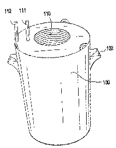
A system for heating storage containers and bodies of water to prevent freezing and ice buildup. Heated fluid lines are utilized to achieve improved thermal transfer of heat energy to bodies of water.


French Abstract

La présente invention se rapporte à un système permettant de chauffer des conteneurs de stockage et des masses d'eau afin d'empêcher la congélation et l'accumulation de glace. Des conduites de fluide chauffées sont utilisées pour réaliser un meilleur transfert thermique de l'énergie thermique aux masses d'eau.

Claims

Note: Claims are shown in the official language in which they were submitted.


Claims:
1. A system for heating a body of liquid, the system comprising:
a cylindrical housing having a bottom surface, an upper lid, and at least one
attachment point;
a cylindrically coiled heated line having an inner coil, an outer coil
disposed
within said cylindrical housing, the cylindrically coiled heated line having
heated fluid traveling
therethrough for heating the liquid that is in contact with an external
surface of the cylindrically
coiled heated line;
a first port connected to and extending vertically from said outer coil and
through
the upper lid of said cylindrical housing;
a second port connected to and extending vertically from said inner coil and
through the upper lid of said cylindrical housing; and
said cylindrically coiled heated line forming a continuous opening extending
from
said second port, through said inner coil, through said outer coil and to said
first port.
2. The system for heating a body of liquid according to claim 1 where said
first port
is an outlet port.
3. The system for heating a body of liquid according to claim 2 where said
second
port is an inlet port.
4. The system for heating a body of liquid according to claim 3 further
comprising a
pump to deliver the heating fluid to said inlet port.
5. The system for heating a body of liquid according to claim 1 wherein
said
attachment point is sufficiently rigid to support the weight of said
cylindrical housing, said
cylindrically coiled heated line and any fluid therein.
6. A system for heating a body of liquid, the system comprising:
6

a boiler for heating fluid, the boiler having a first line and second line;
a cylindrical housing having a bottom surface and an upper lid;
a cylindrically coiled heating line having an inner coil, and an outer coil
disposed
within said cylindrical housing, the cylindrically coiled heating line for
heating the liquid that is
in contact with an external surface of the cylindrically coiled heating line;
a first port connected to and extending vertically from said outer coil and
through
the upper lid of said cylindrical housing and connected to said second line;
a second port connected to and extending vertically from said inner coil and
through the upper lid of said cylindrical housing and connected to said first
line for receiving the
heated fluid provided by the boiler;
said cylindrically coiled heating line forming a continuous opening extending
from said first port, through said inner coil, through said outer coil and to
said second port.
7. The system for heating a body of liquid according to claim 6 where said
first line
is a supply line and said second line is a return line.
8. The system for heating a body of liquid according to claim 7 where said
first port
is an inlet port.
9. The system for heating a body of liquid according to claim 8 where said
second
port is an outlet port.
10. The system for heating a body of liquid according to claim 6 further
comprising a
pump to deliver a heating fluid to said inlet.
11. The system for heating a body of liquid according to claim 6 where said
cylindrical housing further comprises at least one attachment point.
12. The system for heating a body of liquid according to claim 11 wherein
said
attachment point is sufficiently rigid to support the weight of said
cylindrical housing, said
7

cylindrically coiled heating line and any fluid therein.
13. A method for heating a body of liquid at risk of freezing or forming
ice,
comprising the steps of:
placing a cylindrical housing in the body of liquid at risk of freezing such
that the
cylindrical housing is at least partially submerged therein, said cylindrical
housing having a
bottom surface, an upper lid, at least one attachment point and a
cylindrically coiled heating line
having an inner coil and an outer coil disposed therein, including contacting
the body of liquid
with an external surface of the heating line;
connecting a first line of a boiler to a first port of the heating line that
is connected
to and extends vertically from said outer coil and through the upper lid of
said cylindrical
housing;
connecting a second line of the boiler to a second port of the heating line
that is
connected to and extends vertically from said inner coil and through the upper
lid of said
cylindrical housing; and
pumping heated fluid from said boiler and through a continuous heating passage
comprising said second line, said second port, said inner coil, said outer
coil, said first port and
said first line for heating the body of liquid that is in contact with the
external surface of the
heating line.
14. The method of claim 13 where said first line is a return line, said
second line is a
supply line, said first port is an outlet port and said second port is an
inlet port.
15. The method of claim 13, further comprising attaching a crane to the at
least one
attachment point and hoisting the cylindrical housing including the
cylindrically coiled heating
line therein.
8

Description

Note: Descriptions are shown in the official language in which they were submitted.


CA 02810994 2016-10-20
DUGOUT HEATING SYSTEM
[00011
FIELD OF THE INVENTION
[0002] This invention relates to preventing ice buildup in storage
containers. More
particularly, the invention relates to providing a heating a fluid to warm a
liquid inside
storage devices such as dugouts, tanks and ponds. The coiled heating line
thaws and prevents
the accumulation of ice in a large liquid storage device and the heating of
large amounts of
fluid in these large storage devices.
BACKGROUND OF THE INVENTION
[0003] In particular climates it is desired to heat, thaw and prevent the
freezing of fluid
sources such as dugouts, tanks and ponds.
[0004] In large storage containers, keeping fluids from freezing has always
been a serious
problem. In the past hot oilers and heat exchangers have been used. The
drawbacks of these
are that they are inefficient and have high safety risks. Hot oilers arrive at
a site and circulate
fluid through an onboard heat exchanger, raising the temperature of the fluid
to a very high
temperature. In addition to being highly inefficient, these high temperatures,
operating a high
pressure creates a safety risk.
[0005] The hot oiler leaves the site and later returns to start the process
over again. Because
of the in-efficiency of the hot oiler it also makes the operating cost very
high. The process of
heating fluids is less efficient the higher the temperature of the fluid. It
is more efficient to heat
a large volume of fluid to just above freezing and keep it at this temperature
constant then to
heat it up to high temperature and let cool once again.

CA 02810994 2013-03-08
WO 2012/034050
PCT/US2011/051054
[0006] Therefore, a system for keeping high volumes of fluid from freezing
is desired.
[0007] Further, a system for keeping fluids from freezing with minimal
intervention is
desired.
[0008] Even further, a system to provide safe, continuous heat, and to
easily and quickly
thaw or warm bodies of fluid is desired.
SUMMARY OF THE INVENTION
[0009] In one form the invention relates to a system for heating liquid within
a storage
container such as a tank, pond, dugout, cistern or the like. The storage
container having a coiled
heating line with an inlet and an outlet port to pass heated fluid through the
coiled line. The
coiled line is at least partially submerged in the fluid of the storage
container.
[0010] In another embodiment, the invention relates to a system for heating
liquid within a
body of water. The system having a cylindrical housing having a bottom surface
and an upper
lid and a cylindrically coiled heating line having an inner coil, an outer
coil disposed within the
cylindrical housing. The cylindrically coiled heating line having a first port
connected to and
extending vertically from the outer coil and through the upper lid of the
cylindrical housing. The
cylindrically coiled heating line having a second port connected to and
extending vertically from
the inner coil and through the upper lid of the cylindrical housing. The
cylindrically coiled
heating line forming a continuous opening extending from the first port,
through the outer coil,
through the inner coil and to the second port.
[0011] In yet another form, the invention relates to a system for heating
liquid within a body
of water. The system having a boiler with a first line and second line, a
cylindrical housing
having a bottom surface and an upper lid and a cylindrically coiled heating
line having an inner
coil, an outer coil disposed within the cylindrical housing. The cylindrically
coiled heating line
having a first port connected to and extending vertically from the outer coil
and through the
upper lid of the cylindrical housing and connected to the first line. The
cylindrically coiled
heating line also having a second port connected to and extending vertically
from the inner coil
and through the upper lid of the cylindrical housing and connected to the
second line. The
2

CA 02810994 2013-03-08
WO 2012/034050
PCT/US2011/051054
cylindrically coiled heating line forms a continuous opening extending from
the first port,
through the outer coil, through the inner coil and to the second port.
[0012] In another form, the invention relates to a method for heating a body
of water. The
method having the steps of: Placing a cylindrical housing in a body of water,
said cylindrical
housing having a bottom surface, an upper lid, at least one attachment point
and a cylindrically
coiled heating line having an inner coil, an outer coil disposed therein.
Connecting a first line of
boiler to a first port that is connected to and extending vertically from the
outer coil and through
the upper lid of the cylindrical housing. Connecting a second line of boiler
to a second port that
is connected to and extending vertically from the inner coil and through the
upper lid of the
cylindrical housing. Pumping heated fluid from the boiler and through a
continuous heating
lines extending through the first line, the first port, the outer coil, the
inner coil, the second port
and the second line.
BRIEF DESCRIPTION OF THE DRAWINGS
[0013] The present invention is disclosed with reference to the
accompanying drawings,
wherein:
Figs. 1 A ¨ 1C are isometric views of a cylindrical housing having a
cylindrically coiled
heating line according to one embodiment; and
Figs. 2A-2E are various views of the cylindrically coiled heating line.
[0014] Corresponding reference characters indicate corresponding parts
throughout the
several views. The examples set out herein illustrates several embodiments of
the invention but
should not be construed as limiting the scope of the invention in any manner.
DETAILED DESCRIPTION
[0015] Referring to Figs. 1A ¨ 2E, there is shown a cylindrical housing 100
having a
cylindrically coiled heating line 110 within. The housing 100 has a lid 101
and at least one
attachment 102. The attachment points are used to hoist the cylindrical
housing into a body of
3

CA 02810994 2013-03-08
WO 2012/034050 PCT/US2011/051054
water and are sufficiently rigid to support the weight of the cylindrical
housing, the cylindrically
coiled heating line and any fluid therein when attached to a crane and
suspended in the air.
100161 Bodies of water include, but are not limited to ponds, rivers, dugouts,
cisterns and
tanks. In cold weather the liquid is at risk of freezing or forming ice. To
prevent freezing of the
liquid, a cylindrically coiled heating line 110 inside of a cylindrical
housing 100 is used. The
cylindrical housing 100 is at least partially submerged in the body of water.
In the instance that
the body of water is frozen, the cylindrical housing 100 is placed directly on
top of the ice.
Heated fluid enters the cylindrically coiled heating line 110 through the
inlet 111. The heating
fluid travels through the length of the line thereby transferring heat to the
liquid in the cylindrical
housing 100, and then exits through the outlet 112. The coiled heating line
110 contains an outer
coil 113 and an inner coil 114 to increase heat transfer. In one embodiment
additional coils are
used. In one embodiment, the cylindrically coiled heating line is made from a
material that is
resistant to any adverse effects of the liquid, and promotes thermal energy
transfer such as
copper.
10017] The cylindrically coiled heating line 110 has an inlet 111 and an
outlet 112 that extend
vertically up through the lid 101 of the cylindrical housing 100. The inlet
111 and the outlet 112
provide connection points to attach fluid lines to the device. In one
embodiment a boiler is used
to deliver heated fluid to the cylindrically coiled heating line 110 through
the inlet 111. The
fluid returns to the boiler through the outlet 112. It is understood that
while the inlet 111 is
shown extending from the inner coil 114 and the outlet 112 is shown extending
from the outer
coil 113, that these ports can be switched such that the inlet extends from
the outer coil and the
outlet extends from the inner coil.
100181 In one embodiment, the cylindrically heating coil line 110 self
regulates the temperature
of the fluid in the cylindrical housing 100. The cylindrically heating coil
line 110 is attached to a
buoy with a cable long enough to allow the cylindrically heating coil line 110
to be completely
submerged. Hot fluid enters the inlet port 111 and circulates through the coil
line 110. As the
liquid is heated in the housing 100, it rises to the top and exits the housing
100, drawing fresh
liquid from the bottom. As the liquid in the body of water heats, the
cylindrical housing rises out
of the water. The temperature and flow of the liquid exiting the top of the
storage container is
4

I I
CA 2810994 2017-04-26
proportionate to the temperature of the coil, making the pod self regulating,
promoting the
system to operate and optimum efficiency.
[0019] In use, the dugout heating device is lowered into a body of water. A
crane is attached
to the attachment points of the cylindrical housing to move the dugout heating
device to the
desired location. Heated fluid is pumped from a boiler into the inlet port and
through the
cylindrically coiled heating line. The cylindrically coiled heating line
having an inner and an
outer coil. The cylindrically coiled heating line is made from a material that
promotes heat
transfer to heat the body of water in the vicinity of the dugout heating
device. The heating fluid
returns to the boiler through the outlet port to be reheated and the process
is continued. As the
heated fluid flows through the cylindrically coiled heating line the body of
water is thawed (if
frozen) and heated to a sufficient temperature for the desired application.
Once heated, the water
can be pumped away from the body of water and used, even in harsh conditions.
[0020] While the invention has been described with reference to particular
embodiments, it
will be understood by those skilled in the art that various changes may be
made and equivalents
may be substituted for elements thereof without departing from the scope of
the invention. In
addition, many modifications may be made to adapt a particular situation or
material to the
teachings of the invention without departing from the scope of the invention.
[0021] Therefore, it is intended that the invention not be limited to the
particular
embodiments disclosed as the best mode contemplated for carrying out this
invention, but that
the invention will include all embodiments falling within the scope of the
appended claims.
Parts List
100 cylindrical housing
101 lid
102 attachment point
110 cylindrically coiled heating line
111 inlet
112 outlet
113 outer coil
114 inner coil

Representative Drawing
A single figure which represents the drawing illustrating the invention.
Administrative Status

2024-08-01:As part of the Next Generation Patents (NGP) transition, the Canadian Patents Database (CPD) now contains a more detailed Event History, which replicates the Event Log of our new back-office solution.

Please note that "Inactive:" events refers to events no longer in use in our new back-office solution.

For a clearer understanding of the status of the application/patent presented on this page, the site Disclaimer , as well as the definitions for Patent , Event History , Maintenance Fee  and Payment History  should be consulted.

Event History

Description Date
Time Limit for Reversal Expired 2024-03-11
Letter Sent 2023-09-11
Letter Sent 2023-03-09
Letter Sent 2022-09-09
Change of Address or Method of Correspondence Request Received 2019-11-20
Common Representative Appointed 2019-10-30
Grant by Issuance 2017-12-05
Inactive: Cover page published 2017-12-04
Pre-grant 2017-10-19
Inactive: Final fee received 2017-10-19
Notice of Allowance is Issued 2017-05-15
Letter Sent 2017-05-15
Notice of Allowance is Issued 2017-05-15
Inactive: QS passed 2017-05-11
Inactive: Approved for allowance (AFA) 2017-05-11
Amendment Received - Voluntary Amendment 2017-04-26
Inactive: S.30(2) Rules - Examiner requisition 2016-10-26
Inactive: Q2 failed 2016-10-26
Advanced Examination Determined Compliant - PPH 2016-10-20
Amendment Received - Voluntary Amendment 2016-10-20
Advanced Examination Requested - PPH 2016-10-20
Letter Sent 2016-08-22
Request for Examination Requirements Determined Compliant 2016-08-17
All Requirements for Examination Determined Compliant 2016-08-17
Request for Examination Received 2016-08-17
Letter Sent 2014-07-28
Inactive: Multiple transfers 2014-07-21
Inactive: Agents merged 2013-08-14
Inactive: Cover page published 2013-05-10
Inactive: First IPC assigned 2013-04-12
Inactive: Notice - National entry - No RFE 2013-04-12
Amendment Received - Voluntary Amendment 2013-04-12
Inactive: IPC assigned 2013-04-12
Application Received - PCT 2013-04-12
National Entry Requirements Determined Compliant 2013-03-08
Small Entity Declaration Determined Compliant 2013-03-08
Application Published (Open to Public Inspection) 2012-03-15

Abandonment History

There is no abandonment history.

Maintenance Fee

The last payment was received on 2017-08-22

Note : If the full payment has not been received on or before the date indicated, a further fee may be required which may be one of the following

  • the reinstatement fee;
  • the late payment fee; or
  • additional fee to reverse deemed expiry.

Patent fees are adjusted on the 1st of January every year. The amounts above are the current amounts if received by December 31 of the current year.
Please refer to the CIPO Patent Fees web page to see all current fee amounts.

Fee History

Fee Type Anniversary Year Due Date Paid Date
Basic national fee - small 2013-03-08
MF (application, 2nd anniv.) - small 02 2013-09-09 2013-03-08
Registration of a document 2014-07-21
MF (application, 3rd anniv.) - small 03 2014-09-09 2014-08-20
MF (application, 4th anniv.) - small 04 2015-09-09 2015-08-20
Request for examination - small 2016-08-17
MF (application, 5th anniv.) - small 05 2016-09-09 2016-08-19
MF (application, 6th anniv.) - small 06 2017-09-11 2017-08-22
Final fee - small 2017-10-19
MF (patent, 7th anniv.) - small 2018-09-10 2018-09-04
MF (patent, 8th anniv.) - small 2019-09-09 2019-08-30
MF (patent, 9th anniv.) - small 2020-09-09 2020-09-04
MF (patent, 10th anniv.) - small 2021-09-09 2021-09-03
Owners on Record

Note: Records showing the ownership history in alphabetical order.

Current Owners on Record
CERTEK HEAT MACHINE INC.
Past Owners on Record
CALEB BARENDREGT
CALVIN A. G. BARENDREGT
JEREMY BARENDREGT
Past Owners that do not appear in the "Owners on Record" listing will appear in other documentation within the application.
Documents

To view selected files, please enter reCAPTCHA code :


To view images, click a link in the Document Description column (Temporarily unavailable). To download the documents, select one or more checkboxes in the first column and then click the "Download Selected in PDF format (Zip Archive)" or the "Download Selected as Single PDF" button.

List of published and non-published patent-specific documents on the CPD .

If you have any difficulty accessing content, you can call the Client Service Centre at 1-866-997-1936 or send them an e-mail at CIPO Client Service Centre.

({010=All Documents, 020=As Filed, 030=As Open to Public Inspection, 040=At Issuance, 050=Examination, 060=Incoming Correspondence, 070=Miscellaneous, 080=Outgoing Correspondence, 090=Payment})


Document
Description 
Date
(yyyy-mm-dd) 
Number of pages   Size of Image (KB) 
Description 2013-03-07 5 246
Abstract 2013-03-07 2 62
Claims 2013-03-07 3 99
Drawings 2013-03-07 4 67
Representative drawing 2013-04-14 1 5
Claims 2013-03-08 3 96
Description 2016-10-19 5 236
Claims 2016-10-19 3 93
Description 2017-04-25 5 216
Claims 2017-04-25 3 92
Representative drawing 2017-11-19 1 9
Notice of National Entry 2013-04-11 1 196
Courtesy - Certificate of registration (related document(s)) 2014-07-27 1 104
Reminder - Request for Examination 2016-05-09 1 126
Acknowledgement of Request for Examination 2016-08-21 1 177
Commissioner's Notice - Application Found Allowable 2017-05-14 1 163
Commissioner's Notice - Maintenance Fee for a Patent Not Paid 2022-10-20 1 541
Courtesy - Patent Term Deemed Expired 2023-04-19 1 546
Commissioner's Notice - Maintenance Fee for a Patent Not Paid 2023-10-22 1 550
PCT 2013-03-07 7 273
Request for examination 2016-08-16 1 40
Amendment / response to report 2016-10-19 10 327
Examiner Requisition 2016-10-25 3 190
Amendment 2017-04-25 8 236
Final fee 2017-10-18 1 52