Note: Descriptions are shown in the official language in which they were submitted.
CA 02811060 2013-03-111
Pouch-type Packaging
The invention relates to a pouch-type packaging for pourable contents, having
a
front wall and rear wall made from at least one flexible packaging film, such
that
the front wall and the rear wall are joined together via a sealing seam at a
sealing edge and featuring a manual aid-to-opening for the purpose of opening
the pouch and removing the contents.
Today, mainly flat-pouches or sachets in the form of three-sided and four-
sided
pouches, or tube-shaped pouches, are used for packaging portions of ketchup,
mustard and similar small amounts of products that are in a liquid, partially
liquid or paste-like form. The pouches are normally made up of film-type
laminates and feature on the outside a printed, possibly lacquer-covered paper
layer or a plastic film e.g. of PET, oPP, oPA or cellophane. The plastic film
may
also bear print deposited using reverse printing.
The opening of these pouches, which are relatively small in view of the small
amount of contents, normally takes place by tearing the pouch open. For that
purpose, in the region intended for opening, a weakness in the material which
serves as a place for initiating the tearing action may be provided e.g. in
the
form of laser-cut lines which extend over only part of the thickness of the
film-
type laminate. Another place for initiating tearing is e.g. a tearing notch
which is
normally situated in a sealing seam. To open the pouch, the pouch is normally
gripped at two places between finger and thumb of each hand and the opening
achieved by a tearing action which is effected by a relative movement of both
hands.
A known aid-to-opening comprises a notch which is introduced in the packaging
line in a sealing seam, normally in the finished pouch. Another known aid-to-
opening is such that, prior to pouch production, the laminate is weakened
locally by means of laser cutting in the intended area of opening. In both
cases
there is the possibility that the barrier layer present may be damaged or a
notch
may extend into the non-sealed region. In both cases there is the possibility
that
CA 02811060 2013-03-11
2
an integral barrier layer may be damaged or a notch extends into the non-
sealed region.
A further disadvantage of the known aids-to-opening in the form of notches and
laser cuts is that, even on carefully tearing open the pouch, some of the
contents escapes from the pouch during tearing and unintentionally sticks to
the hands.
The object of the invention is to provide a pouch-type packaging of the kind
mentioned at the start which exhibits a manual opening system by means of
which it is possible to avoid contamination of the hands with contents
escaping
from the pouch when the opening procedure is correctly carried out.
That objective is achieved by way of the invention in that, in the front wall
of the
pouch a distance from the sealing seam, a free end of a sealing zone is
provided furthest removed from the sealing edge, and at least the front wall
of
the pouch exhibits an outer layer on the side facing the outside of the pouch,
whereby the outer layer and the part of the front wall of the pouch lying
under
the outer layer delimit an outlet zone for the contents in an area which encom-
passes the free end of the sealing zone.
In a first preferred embodiment of the pouch-type packaging according to the
invention the sealing seam is extended in a region bordering the sealing edge
and the outlet zone up to a sealing zone directed away from the sealing edge,
and the outlet zone extends to a peripheral edge of the sealing edge.
In a second preferred embodiment of the pouch-type packaging according to
the invention the sealing zone and the outlet zone are arranged a distance
from
the sealing seam and the outer layer exhibits a line of weakness or a
separating
line as outlet region for the contents to be poured out of the pouch.
In a first preferred version of the pouch-type packaging according to the
invention the outer layer in the outlet zone is bonded to the underlying part
of
CA 02811060 2013-03-11
3
the front wall of the pouch less strongly than it is outside the outlet zone
and
can be peeled away from that underlying part of the front wall.
In a second preferred version of the pouch-type packaging according to the
invention the outer layer in the outlet zone is freed from the part of the
front wall
of the pouch lying under the outer layer.
In a third preferred version of the first preferred embodiment of the pouch-
type
packaging according to the invention the outer layer in the outlet zone is
freed
from the part of the pouch front wall lying under the outer lay up to a region
in
the sealing edge and is bonded in the region in the sealing edge to the part
of
the pouch front wall under the outer layer less strongly than outside the
outlet
zone and can be peeled away from that part of the front wall.
In the first preferred embodiment of the pouch-type packaging according to the
invention the sealing zone may be in the form of a triangle with its base
lying
parallel to the sealing edge and sides forming a peak a distance from the
sealing edge. The sealing zone may, however, also be in the form of a strip
which preferably runs perpendicular from the sealing edge and exhibits a free
end. Usefully, the outlet zone is delimited by two borderlines that run
essentially
parallel to each other and perpendicular to the sealing edge. The outlet zone
may, however, also be delimited by border lines that preferably run towards
one
end of the sealing seam in the region of a corner of the pouch.
In the second preferred embodiment of the pouch-type packaging according to
the invention the sealing zone is likewise preferably in the form of a
triangle with
its base lying parallel to the sealing edge and sides forming a peak a
distance
from the sealing edge. Usefully, the outlet zone is delimited by two border
lines
that run essentially parallel to each other and perpendicular to the sealing
edge
and two border lines that run essentially parallel to each other and parallel
to
the sealing edge.
Packaging films that are suitable as front and rear walls of the pouch exhibit
a
CA 02811060 2013-03-11
4
sealing layer on the side that forms the inner facing side of the finished
pouch
and can be sealed to each other. Thereby, the sealing layer may be bonded to
a substrate layer via an adhesive. The sealing layer may, however, also be
deposited directly on a substrate layer by means of extrusion coating. Under
certain circumstances it is also possible to manufacture a sealing layer and
substrate layer by co-extrusion.
The outer layer on the side of the front wall of the pouch which forms the
outer
layer in the finished pouch is, in the region out with the outlet zone for the
contents, permanently joined by means of an adhesive layer to a substrate
layer lying under the outer layer.
In the regions within the outlet zone the outer layer can be peeled away from
the substrate layer or is not joined to it. If desired, within the outlet
zone, the
outer layer may be sealed to the substrate layer in a manner that enables
separation by peeling only in the region of the sealing edge and, outwith the
sealing edge, be free from the substrate layer.
The sealing layer and the substrate layer may form a single common layer. The
sealing layer, the substrate layer and the outer layer may also each be in the
form of a single layer or be multi-layered.
The sealing layers are normally polyethylenes e.g. LDPE, LLDPE, MDPE and
mixtures thereof or co-extruded metallocene polyethylenes and inomers e.g.
Surlyn , or co-extruded films of these materials with PE as substrate layer.
For
special applications polypropylenes may be employed. The thickness of the
sealing layers lie in the range of 10 to 100 pm, preferably 15 to 75 pm.
Suitable substrate layers are foils of metal, in particular aluminium or an
aluminium alloy. These serve simultaneously as barrier layer against the
passage of oxygen, water vapour and aromas. The thickness of the aluminium
foil used as a barrier layer for the pouch is approximately 5 to 30 pm,
preferably
7 to 15 pm.
CA 02811060 2013-03-11
5
Suitable outer layers are biaxial oriented plastic films of polyesters,
polypropyl-
ene or polyamide. A preferred polyester is PET (polyethylene-terephthalate)
preferably with a thickness of 8 to 20 pm, in particular 12 pm. The plastic
film
employed as outer layer may be printed on the outside and, if desired, be
provided with a coating having good sliding properties, or may be counter-
printed. Instead of a plastic film, it is possible to employ a paper layer
coated
with plastic as the outer layer.
Instead of a barrier layer in the form of an aluminium foil it is also
possible to
employ other barrier layers e.g. thin ceramic layers of silicon oxide and/or
aluminium oxide which are deposited by sputtering or by precipitation in
vacuum, or plastic films e.g. materials from the series of vinyl alcohols e.g.
of
ethyl-vinyl-alcohol-polymers or polyvinylidenchloride.
The front wall and the rear wall of the pouch may be of the same material or
may be different in their layered structure. Normally, the front and rear
walls of
the pouch are made of the same packaging film.
The pouch-type forms of packaging according to the invention are in particular
3 and 4 sealing edge pouches and tube-like pouches featuring one longitudinal
and two transverse seams. The scope of the invention includes amongst others
a packaging whereby the rear wall of the pouch is in the form of a flexible
pouch-type container made by thermoforming or cold forming and having a
peripheral sealing and the front wall of the pouch is sealed as lid onto the
sealing area.
Further advantages, features and details of the invention are revealed in the
following description of preferred exemplified embodiments and with the aid of
the drawing; this shows schematically in
Fig. 1 a plan view of the front side of a flat pouch with opening system;
Fig. 2 a section through the unopened flat pouch in Fig. 1 along line I-I;
CA 02811060 2013-03-116
Fig. 3 the section shown in Fig. 2 after opening the flat pouch;
Fig. 4 a perspective view of the tube-shaped pouch in Fig. 1 in
the
unopened state;
Fig. 5 the tube-shaped pouch in Fig. 4 after opening;
Fig. 6 a plan view of part of the front side of the flat pouch in
Fig. 1 with
different shapes of outlet zone for the contents;
Fig. 7 a plan view of part of the front side of the flat pouch in
Fig. 1 with
different shapes of sealing zone;
Fig. 8 a plan view of part of the front side of the flat pouch in
Fig. 7 with
different shapes the outlet zone for the contents;
Fig. 9 a plan view of part of the front side of the flat pouch in
Fig. 7 with
variable relationship between the length of the sealing zone and
its distance from the sealing edge at the side;
Fig. 10 a graphic representation of the relationship between burst
strength
and the product of the variables in Fig. 9;
Fig. 11 a first layer structure of a packaging film for the
production of a
pouch-type packaging;
Fig. 12 a second layer structure of a packaging film for the
production of a
pouch-type packaging;
Fig. 13 a plan view of the front side of the flat pouch in Fig. 1
with sealing
and outlet zones arranged outside the sealing seam;
CA 02811060 2013-03-11
7
Fig. 14 removal of contents from the pouch shown in Fig. 13.
Shown in Figs. 1 and 2 is by way of example a version of pouch-type packaging
in the form of a so-called 4-sided sealing edge pouch with four sealing
5 edges 16, 18, 20, 22 arranged in a rectangle; the said pouch is comprised
essentially of two facing packaging films forming a front side and a rear side
of
the pouch. The packaging film forming the front side of the pouch, hereafter
referred to as the front wall 12 of the pouch, and the packaging film forming
the
rear side of the pouch, hereafter referred to as the rear wall 14 of the
pouch,
10 are joined together by an essentially strip-shaped sealing seam 24 running
round the pouch-type packaging 10 along the sealing edges 16, 18, 20, 22 thus
enclosing a space 13 for the contents.
The pouch-type packaging 10 normally contains pourable contents 11, in
particular in a liquid, partially liquid or paste-like form. Pouch-type forms
of
packaging 10 include e.g. the known pouches for delivering portions of
ketchup, mustard, mayonnaise and the like foodstuffs as contents 11.
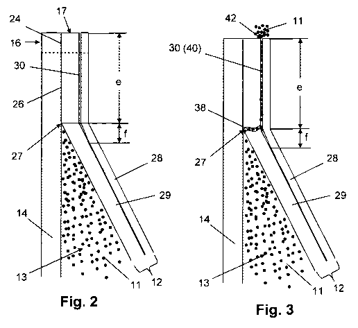
In a region intended for opening the pouch, bordering the sealing edge 16, the
strip-shaped sealing seam 24 is extended to a sealing zone 26 in the form of
an
equilateral triangle with a base line c parallel to the sealing edge 16 and
two
sides a and b forming a peak 27 a distance e from the sealing edge 16.
The side of the front wall 12 facing the inside of the pouch 10 can be sealed
onto the side of the rear wall 14 likewise facing the inside of the pouch 10.
The
outward facing side of the front wall 12 features an outer layer 28. In an
outlet
zone 30 for the contents 11 which encloses the peak 27 of the sealing zone 26,
the outer layer 28 adheres to the underlying part 29 of the front wall 12 with
less
adhesive strength or is free from the underlying part 29 of the front wall 12.
In the embodiment shown in Fig. 1 the outlet zone 30 is delimited by a border
line 32 running parallel to the sealing edge 16 and two border lines 34, 36
which run parallel to each other and perpendicular the sealing edge 16 and
CA 02811060 2013-03-11
8
form the transition of the outer layer 28 from the permanent join to the
underlying part 29 of the front wall 12 to the separable or non-adhesive join
in
the outlet zone 30. The border line 32 running parallel to the sealing edge 16
¨
as seen in plan view ¨ is situated a distance f from the peak 27 of the
sealing
zone 26.
If the pouch 10, filled with contents 11, is pressed from the outside ¨ which
in
practice is achieved e.g. by pressing the pouch 10 between the thumb and
index finger of one hand ¨ then a fold is created in the pouch 10 in such a
manner that the tension which acts on the pouch walls that are sealed to each
other at the transition from the interior space to the sealing joint, reaches
a
maximum at the peak 27 of the sealing zone 26. On exceeding the elongation
at fracture of the part 29 of the front wall 12 lying under the outer layer
28,
which is weakened by the reduced or missing adhesion to the outer layer 28, a
rupturing or local separation of this part 29 of the front wall 12 occurs thus
creating an opening slit 38 (Fig. 3).
After the local separation of the part 29 of the front wall 12 lying under the
outer
layer 28 in the region of the peak 27 of the sealing zone, further application
of
pressure to the pouch 10 causes the contents to be pressed out of the inner
space 13 through the opening slit 38 into an intermediate space or channel 40
formed by the part 29 of the pouch front wall 12 and the outer layer 28 in the
outlet zone 30 and leaves the pouch 10 through an outlet opening 42, which is
formed at an end edge 17 of the sealing edge 16 by part 29 of the front wall
12
lying under the outer layer 28 and the outer layer 28.
The opening mechanism in the pouch-type packaging 10 shown in Figs. 1 to 3
is shown in greater detail in Figs. 4 and 5. Fig. 5 shows that, on applying
pressure to the pouch 10 held between the index finger 46 and the thumb 48 of
one hand 44, contents 11 are expressed at the edge 17 of the sealing edge 16
through the outlet opening 42 formed by the part 29 of the pouch front wall 12
and the outer layer 28. Further, it can be seen from Fig. 5 that the opening
in
the pouch-type packaging 10 and the removal of the contents 11 takes place by
CA 02811060 2013-03-11
9
single-handed operation. Thereby, the index finger and thumb effecting the
compression of the pouch are situated a distance from the outlet opening such
that ¨ as cannot be reliably avoided even on correctly opening conventional
pouches ¨ any contamination of the contents is prevented here.
As shown in Fig. 6, in the case of a variant of the pouch-type packaging
illustrated in Figs. 1 to 5, the channel 40 formed by the outlet zone 30 and
delimited by two boundary lines 34', 36' runs along one side of the triangular-
shaped sealing zone 26 to the sealing edge 16, such that outlet opening 42 is
situated in a corner of the pouch at the edge 17 of the sealing edge 16.
Shown in Fig. 7 is a further version of a pouch-type form of packaging 10 in
accordance with Fig. 1 in which, instead of a triangular sealing zone 26 ¨
starting from sealing edge 16 and extending the strip-shaped sealing strip 24
¨
a sealing zone 26' which projects from the sealing edge 16 or from the strip-
shaped sealing seam 24 is provide in the form of a strip with a free end 27'
instead of the triangular peak 27.
Here the free end 27' of the strip-shaped sealing zone 26' is, as in the
embodiment with the triangular sealing zone 26 shown in Figs. 1 to 5, enclosed
by the outlet zone 30. Also here the outlet zone 30 is delimited by one
barrier
line 32 running parallel to the sealing edge 1 and two barrier lines 34, 36
running perpendicular to the sealing edge 16.
Shown in Fig. 8 is a version of the example shown in Fig. 7 where the channel
40 formed by the outlet zone 30 and delimited by two border lines 34', 36'
runs
along one side of the strip-shaped sealing zone 26' to the edge 17 of the
sealing seam 16.
Rupture tests were carried out on pouch-type forms of packaging with a strip-
shaped sealing zone 26' that projects from a sealing edge and serves to
provide an opening slit in the packaging film, and the rupture strength deter-
mined as a function of the distance X of the strip-shaped sealing zone 26'
from
CA 02811060 2013-03-11
10
a pouch sidewall and of the distance Y of the free end 27' of the strip-shaped
sealing zone 26' from the sealing edge 16. The packaging film employed for
production of 4-sided pouches was a laminate having the following structure:
PET 12 pm / Al 8 pm / PE 70 pm
PET Polyethylenterephthalate
Al Aluminium foil
PE Polyethylene
The same laminate was used for the front wall 12 and for the rear wall 14 of
the
pouch; the sealing was made with PE onto PE. The circumferential sealing
seam 24 and the strip-shaped sealing zone 26' were produced as corrugated or
wave-shaped seal with waves arranged in the direction that the sealing seam
24 runs or in the longitudinal direction of the strip; a flat version of the
sealing
seam 24 was also made for comparison purposes. The build up of pressure in
the pouch until rupture occurred was at a rate of 50 mbar/sec. The results of
the rupture tests are presented in table 1 and the calculated product X*Y
shown
in Fig. 10 as individual values along with the line of regression.
Table 1: Rupture trials
Pouch-No. Type of seal
Y [mm] X [mm]
Pressure at rupture [mbar] X *
Y [mm]
1 corrugated
0 0
937 0
2 corrugated
8 9
703 72
3 corrugated
9 16
663 144
4 corrugated
10 13
740 130
5 corrugated
11 30
428 330
6 corrugated
12 23
461 276
7 corrugated
12 7
798 84
8 corrugated
30 11
299 330
9 corrugated
32 6
777 192
10 corrugated
32 19
297 608
11 corrugated
40 16
261 640
12 flat
0 0
800 0
13 flat
0 0
881 0
14 flat
18 20
467 360
15 flat
41 16
343 656
CA 02811060 2013-03-11
11
The rupture trials make it possible to determine in a simple manner the
optimum dimensions and arrangement of the strip-shaped sealing zone 26'
required for the lowest possible rupture strength.
Shown in Figs. 11 and 12 is the make up of two packaging films that are
suitable for the manufacture of pouch-type forms of packaging 10.
In the case of the packaging film shown in Fig. 11 a sealing layer 50 is
deposited onto the substrate layer 52 on the side of the packaging film that
will
face the interior of the finished pouch by means of extrusion coating or
bonded
to the substrate layer 52 by way of a layer of adhesive. The side of the
substrate layer 52 facing the outside of the pouch made from the packaging
film
is permanently bonded to the outer layer 28 by way of a first bonding material
54. In the region foreseen for the outlet zone 30 for the contents 11 the
outer
layer 28 is either not joined to the underlying substrate layer 52 over a bond-
free zone 58, or attached via a second bonding material 56 such that it can be
separated by a peeling action. The first bonding material 54 for creating a
permanent join is an adhesive based on polyurethane (PU). The second
bonding material 56 for creating a separable join is e.g. a hot-melt or a hot-
sealing coating. The sealing layer 50 is comprised e.g. of a polyethylene
(PE),
the substrate layer 52 of an aluminium foil and the outer layer of
polyethylene-
terephthalate (PET).
The make up of the packaging film in Fig. 12 corresponds to that of the film
shown in Fig. 11, except in that here the sealing layer 50 also contains the
substrate and is comprised e.g. of a polyethylene.
The same packaging film may be employed for the front wall 12 and the rear
wall 14 of the pouch. The deposition of the second bonding material 56 to
create the separable regions may take place using a printing process e.g.
index
printing.
CA 02811060 2013-03-11
12
In a further version of the pouch illustrated in Figs. 1 to 5, shown in Fig.
13, a
sealing zone 26" in the form of an equilateral triangle with base c lying
parallel
to the sealing edge and two sides a, b forming a peak 27" facing away from the
sealing edge is provided about in the middle of the front wall, a distance
from
the strip-shaped sealing seam 24. The area of the outlet zone 30 for the
contents 11 encloses the whole of the sealing zone 26" and is likewise on all
sides a distance from the sealing edge 16 and the sealing seam 24. Within the
area of the outlet zone 30 the outer layer 28 is provided with a line of
weakness
or separating cut 37 running through the outer layer forming a slit-shaped
open-
ing for removing the contents 11 of the pouch 10. In the example shown the
separating cut 37 runs parallel to the sealing seam 16 and is arranged between
the sealing edge 16 and the sealing zone 26".
In the embodiment shown in Fig. 13 the outlet zone 30 is delimited by two
border lines 32, 33 running parallel to the sealing edge 16 and two border
lines
34, 36 which run parallel to each other and perpendicular to the sealing edge
16 and form the transition in the outer layer 28 from the permanent attachment
to the underlying part 29 of the pouch front wall 12 to the peelable or non-
adhesive connection in the outlet zone 30.
The pouch-type packaging 10, shown in Fig. 13, for removal of the contents
through the front wall 12 of the pouch 10 has pressure applied to it from
outside
by folding the pouch and pressing together the two resulting halves of the
pouch, which in practice ¨ as shown in Fig. 14 ¨ is achieved e.g. using the
thumb 48 and index finger 46 of one hand. As already explained in the case of
pouch 10 in Figs. 1 to 5, the folding of the pouch 10 is also performed here
in
such a manner that the tensile force which acts on the pouch walls that are
sealed together reaches a maximum at the transition from the interior 13 to
the
sealing joint at the peak 27" of the sealing zone 26". On exceeding the elong-
ation at fracture of that part 29 of the pouch front wall 12 in the outlet
zone 30
lying under the outer layer 28 - where the bonding of the outer layer 28 is
reduced or missing - fracture or local separation of this part 29 of the pouch
front wall 12 occurs forming an opening slit 38.
CA 02811060 2013-03-1113
After the local separation of the part 29 of the pouch front wall 12 lying
under
the outer layer 28 in the region of the peak 27" of the sealing zone 26" and
continuing to apply pressure to the pouch 10, the contents 11 emerge from the
interior 13 through the opening slit 38 in the part 29 of the pouch front wall
12
lying under the outer layer 28 and through the outer layer into the
intermediate
space or channel 40 in the outlet zone 30 and leave the pouch 10 via the slit-
shaped opening formed in the outer layer 28 by the line of weakness or line of
separation 37.
By pouch-type packaging is also to be understood packaging in which the rear
wall 14 of the pouch is in the form of a flexible container manufactured e.g.
by
thermoforming or cold forming featuring a peripheral sealing area and where
the front wall 12 of the pouch is sealed onto the sealing area as a lid.