Note: Descriptions are shown in the official language in which they were submitted.
CA 02811531 2013-03-18
PCT/AU2011/001214
Received 16/02/2012
1
"Tent Peg"
=
Field of the Invention
The present invention relates to tent pegs. =
Background to the Invention
Tent pegs used for securing down a tent are commonly lost either in use or
transport. After use, the tent pegs can be left in the ground due to being
hard
to locate among grass or other ground cover. For the tent pegs that are
located and removed, the pegs are often simply placed in a pile while the tent
is being dismantled. The pegs are then usually collected and placed in a bag
for transport. This process can also result in the loss of tent pegs, which
may
not be noticed until next time the tent is to be used.
The present invention relates to tent pegs aimed at providing easier storage
and transport and reducing the likelihood of the pegs being lost.
Summary of the Invention
According to one aspect of the present invention there is provided a tent peg
comprising a shaft and a head, wherein the head comprises a body having an
arm ,extending therefrom and the arm includes a first aperture adjacent the
body and a second aperture located between the first aperture and a distal
end of the arm such that the shaft of a first further tent peg is receivable
in the
first aperture of the tent peg in an opposite orientation, the shaft of a
second
further tent peg is receivable in the second aperture in the same orientation
as
the tent peg and wherein the shaft of the second further tent peg is
receivable
in the first aperture of the first further tent peg.
Preferably, the second aperture comprises an elongate aperture for receiving
the shafts of two further tent pegs such that the shaft of a third further
tent peg
AMENDED SHEET
1PEA/AU
= .
CA 02811531 2013-03-18
PCT/AU2011/001214
Received 16/02/2012
2
is receivable through the second aperture in an opposite orientation to the
tent
peg and also through the second aperture of the first further tent peg and the
first aperture of the second further tent peg.
Preferably the arm extends generally radially from the cylindrical body and
=
includes a first portion extending from the body generally perpendicularly
from
the longitudinal axis of the shaft and a second portion extending at an angle
to
the first portion, the second portion being angled towards the second end of
the shaft.
Preferably the first portion includes the first aperture and the second
portion
includes the second aperture.
In one embodiment, the body comprises a cylindrical body having a
longitudinal aperture therein for receiving the shaft and the shaft includes a
widened end portion received and secured in use Within the cylindrical body.
The body preferably includes a narrowed neck portion such that the shaft can
slide through aperture but the neck portion restricts passage of the widened
end of the shaft.
In a preferred embodiment, the top of the widened end protrudes above the
body of the head such that the top may be struck by a tool for driving the
tent
peg into the ground.
The head is preferably constructed of a plastic material and the shaft is
preferably constructed of metal.
AMENDED SHEET
1PEA/AU
CA 02811531 2013-03-18
WO 2012/037605 3
PCT/AU2011/001214
Preferably the head is constructed of a brightly coloured material and/or a
material that glows in the dark.
Brief Description of the Drawings
The invention will now be described, by way of example, with reference to the
following drawings:
Figure 1 is a perspective view of a tent peg in accordance with the present
invention;
Figure 2 is an exploded view of the tent peg of Figure 1;
Figure 3a is a side cross sectional view of the tent peg of Figure 1;
Figure 3b is a front view of the tent peg of Figure 1;
Figure 4a is a top view of the tent peg of Figure 1;
Figure 4b is a side view of the tent peg of Figure 1;
Figure 4c is an upper perspective view of the tent peg of Figure 1;
Figure 5 is a perspective view of a plurality of the tent pegs of Figure 1
interconnected;
Figure 6 is a perspective view showing installation of one of the tent pegs of
Figure 1; and
Figure 7 is a perspective view showing removal of one of the tent pegs of
Figure 1.
Detailed Description of Preferred Embodiments
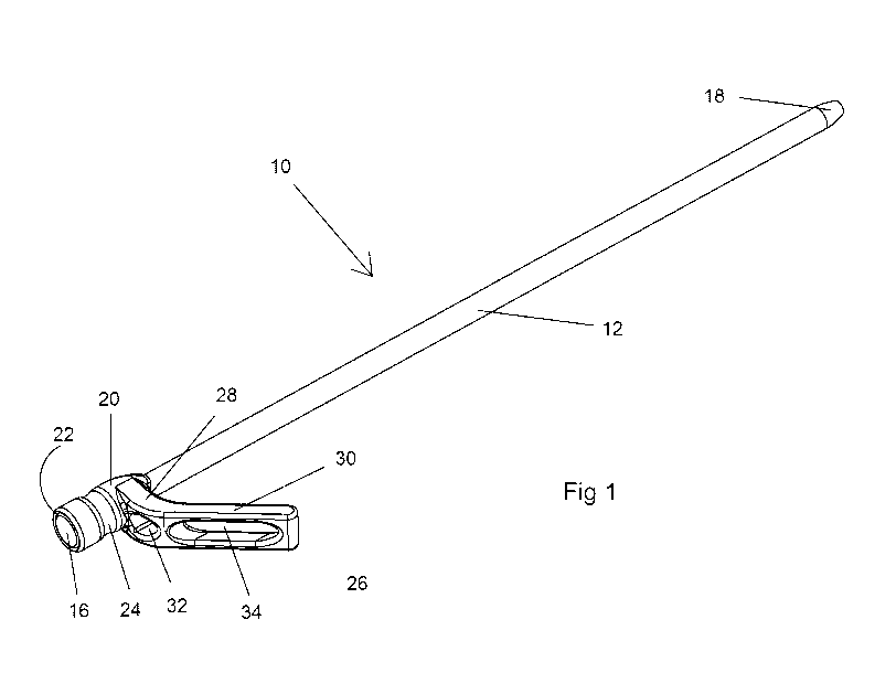
Referring to the Figures, there is shown a tent peg 10 comprising a shaft 12
and a head 14. In the embodiment shown, the shaft 12 and the head 14 are
separate components connectable together to form the tent peg 10. It will be
appreciated however that the shaft 12 and head 14 may be integrally formed.
The shaft 12 comprises an elongate spike of suitable material, such as metal.
The shaft 12 includes a widened end 16 at a first end thereof and a tapered
CA 02811531 2013-03-18
WO 2012/037605 4
PCT/AU2011/001214
portion 18 at a second end. The tapered portion 18 is provided for being
driven into the ground.
The head 14 includes a body 20 having a longitudinal aperture 22 therein. In
the embodiment shown, the body 20 comprises a cylindrical body. The
longitudinal aperture 22 is provided for receiving the shaft 12. The shaft 12
is
inserted into the aperture 22 with the second end first. The body 20 includes
a narrowed neck portion 24 such that the shaft 12 can slide through aperture
22 but the neck portion 24 restricts passage of the widened end 16 of the
shaft 12. The widened end 16 of the shaft 12 is therefore retained within the
body 12 adjacent a first end thereof.
The widened end 16 of the shaft 12 is accessible through the first end of the
body 12 such that the widened end 16 can be struck with a suitable
implement, such as a hammer, in order to drive the tent peg 10 into the
ground. That is, the top of the widened end 16 protrudes above the body 20 of
the head 14. As the impact is taken by the widened end 16 of the shaft 12, the
head 14 may be constructed of a material of lesser strength, such as plastic.
The head 14 is preferably constructed of a brightly coloured plastic to make
the tent pegs 10 easier to see when in the ground. The head 14 may also be
constructed of a material that glows in the dark.
The head 14 includes an arm 26 extending outwardly therefrom. The arm 26
in the embodiment shown extends outwardly from the head 24 between a
second end of the body 20 and the neck portion 24. The arm 26 extends
generally radially from the cylindrical body 20.
The arm 26 comprises a first portion 28 and a second portion 30. The first
portion 28 extends from the body 20 generally perpendicularly from the
longitudinal axis of the shaft 12. The second portion 30 extends at an angle
to
the first portion 28, being angled towards the second end of the shaft 12. In
use, the arm 26 traps a rope secured around the tent peg 10 between the arm
26 and the ground in a known manner.
CA 02811531 2013-03-18
WO 2012/037605 5
PCT/AU2011/001214
The arm 26 includes at least one aperture for receiving the shaft of a further
tent peg 10 such that a plurality of tent pegs 10 can be secured together when
not in use.
The arm 26 of the tent peg 10 includes a first aperture 32 provided in the
first
portion 28 of the arm 26 adjacent the body 20. The first aperture 32 is
provided for receiving the second end of a first further tent peg 10'. The
second end of the first further tent peg 10' is inserted into the first
aperture 32
from a side adjacent the second end of the body 20 such that the head 14 of
the first further tent peg 10' is located adjacent the second end 18 of the
shaft
14. That is, the first further tent peg 10' is arranged in the opposite
direction.
The arm 26 includes also a second aperture 34 in the second portion 18
thereof. The second aperture 34 is provided between the first aperture 32 and
the distal end of the arm 26. The second aperture 34 comprises an elongate
aperture such that the shafts 12 of two further tent pegs can be received in
the
second aperture 34.
As described above, a first further tent peg 10' is received in the first
aperture
32 oriented in the opposite direction. A second further tent peg 10" is then
oriented in the same direction as the initial tent peg 10 and the shaft 12
thereof inserted through the second aperture 34. The shaft 12 of the second
further tent peg 10" is also received through the first aperture 32 of the
first
further tent peg 10'. An end of the cylindrical body 20 of the head 14 is
provided with a tapered side 21 (as can be seen in Figure 2). The tapered
side 21 is provided at an angle being the same as that of the second portion
of the arm 26 such that the tapered side 21 rests flat against the arm 26.
A third further tent peg 10¨ is then oriented in the same direction as the
first
30 further
tent peg 10' and inserted through the second aperture 34 of the first
further tent peg 10'. The shaft 12 of the third further tent peg 10" is also
received in the second aperture 34 of the initial tent peg 10 and the first
aperture 32 of the second further tent peg 10".
CA 02811531 2013-03-18
WO 2012/037605 6
PCT/AU2011/001214
In this way, a plurality of tent pegs 10 can be interconnected (as shown in
Figure 5) with each tent peg 10 in the opposite orientation to the adjacent
tent
pegs 10. The arm 26 of each of the tent pegs 10 receives the shafts 12 of
three further tent pegs 10. The interlocking of multiple further tent pegs 10
into
the arm 26 of each tent peg 10 creates a single planar row of interconnected
tent pegs 10 that form a relatively rigid structure.
In use, the tent pegs 10 can be inserted into the ground and used in the
normal manner of tent pegs (as shown in Figure 6). Each tent peg 10 may be
removed by grasping the head 14 of the tent peg 10 and pulling it from the
ground (as shown in Figure 7). The brightly coloured or glowing heads 14 will
aid the ability to locate each of the tent pegs 10.
Each time a tent peg 10 is removed it may be interconnected to the previously
removed tent pegs 10 as described above. In this way, the tent pegs 10 are
retained together in a single structure, reducing the likelihood of the tent
pegs
10 becoming lost.
It will be readily apparent to persons skilled in the relevant arts that
various
modifications and improvements may be made to the foregoing embodiments,
in addition to those already described, without departing from the basic
inventive concepts of the present invention.