Note: Descriptions are shown in the official language in which they were submitted.
CA 02811870 2016-04-20
- 1 -
AIR CONDITIONER
Technical Field
[0001] The
present invention relates to an air conditioner that performs a warming
operation and a defrosting operation.
Background Art
[0002] A conventional air conditioner is disclosed in patent literature
document 1.
This air conditioner includes an indoor apparatus disposed indoors and an
outdoor
apparatus disposed outdoors. The outdoor apparatus is provided with a
compressor, an
outdoor heat exchanger, and an outdoor fan, while the indoor apparatus is
provided
with an indoor heat exchanger and an indoor fan. The compressor flows a
refrigerant
to operate a refrigeration cycle.
[0003] A refrigerant outlet portion of the compressor is connected to
one end of the
indoor heat exchanger and one end of the outdoor heat exchanger via a four-way
valve
by means of a refrigerant pipe. The other ends of the indoor heat exchanger
and
outdoor heat exchanger are connected to each other via an expansion valve by
means
of the refrigerant pipe. The outdoor fan is disposed to oppose the outdoor
heat
exchanger and prompts a heat exchange between the outdoor heat exchanger and
outdoor air. The indoor fan introduces indoor air into the indoor apparatus
and sends
the air, performing the heat exchange with the indoor heat exchanger, into a
room.
[0004] During a warming operation time, the refrigerant output from the
compressor
thanks to switching of the four-way valve flows through the indoor heat
exchanger,
the expansion valve, the outdoor heat exchanger and returns to the compressor.
In this
CA 02811870 2013-08-09
, .
- 2 -
way, the indoor heat exchanger forms a high temperature portion of the
refrigeration
cycle, while the outdoor heat exchanger forms a low temperature portion of the
refrigeration cycle. The indoor air rises in temperature thanks to the heat
exchange
with the indoor heat exchanger and is sent into the room, whereby the indoor
warming
is performed. During this time, the indoor heat exchanger performs the heat
exchange
with the indoor air; as a result, the temperature of the indoor heat exchanger
is lowered,
while the outdoor heat exchanger performs the heat exchange with outdoor air
to be
raised in temperature thanks to driving of the outdoor fan.
[0005]
During a cooling operation time, the refrigerant output from the compressor
thanks to the switching of the four-way valve flows in a direction opposite to
the
direction during the warming operation time. In other words, the refrigerant
flows
through the outdoor heat exchanger, the expansion valve, the indoor heat
exchanger
and returns to the compressor. In this way, the outdoor heat exchanger forms
the high
temperature portion of the refrigeration cycle, while the indoor heat
exchanger forms a
low temperature portion of the refrigeration cycle. The indoor air falls in
temperature
thanks to the heat exchange with the indoor heat exchanger and is sent into
the room,
whereby the indoor cooling is performed. During this time, the indoor heat
exchanger
performs the heat exchange with the indoor air; as a result, the temperature
of the
indoor heat exchanger is raised, while the outdoor heat exchanger performs the
heat
exchange with outdoor air to be lowered in temperature thanks to driving of
the
=
outdoor fan.
[0006]
Besides, if the outdoor heat exchanger has frost during the warming operation
time, a defrosting operation is performed. During a defrosting operation time,
the
CA 02811870 2016-04-20
- 3 -
indoor fan and the outdoor fan are stopped, and the refrigerant flows in the
same
direction as the direction during the cooling operation time thanks to the
switching of
the four-way valve. In this way, the outdoor heat exchanger forms a high
temperature
portion of the refrigeration cycle, accordingly, it is possible to defrost the
outdoor heat
exchanger.
Citation List
Patent Literature
[0007] PLT1: JP-A-2010-181036 (pages 4 to 6, Fig. 1)
Summary of Invention
[0008] However, according to the above conventional air conditioner, in
a cold area
and the like, if it goes down to an extremely low temperature outdoors in a
place
where the outdoor heat exchanger is installed, a high-temperature refrigerant
output
from the compressor during a defrosting operation time is deprived of heat by
outdoor
air, whereby a temperature rise of the outdoor heat exchanger is prevented.
Especially,
in a situation where a strong wind blows outdoors, the outdoor fan is rotated
by the
strong wind, whereby the temperature rise of the outdoor heat exchanger is
further
prevented.
[0009]
Because of this, even if the defrosting operation is performed for a
predetermined time, the outdoor heat exchanger does not rise to a 'desired
temperature,
accordingly, defective defrosting occurs, in which frost remains. According to
this, the
defrosting operation is performed repeatedly during a short time and the
defective
defrosting is repeated, accordingly, there is a problem that the indoor
warming is not
CA 02811870 2016-04-20
- 4 -
performed and convenience of the air conditioner deteriorates. Besides,
because of the
defective defrosting, the frost remaining on the outdoor heat exchanger grows
and the
outdoor apparatus is covered by ice to cause the outdoor apparatus to
malfunction,
whereby there is also a problem that the air conditioner is undermined in
reliability.
[0010] An aspect of the present invention provides an air conditioner that
is able to
reduce defective defrosting and improve convenience and reliability.
[0011] To
achieve the above, the present invention is characterized to include: a
compressor that operates a refrigeration cycle; an outdoor heat exchanger that
is
disposed outdoors; an indoor heat exchanger that is disposed indoors; an
outdoor fan
that supplies outdoor air to the outdoor heat exchanger; and an indoor fan
that supplies
indoor air to the indoor heat exchanger, wherein the indoor fan and the
outdoor fan are
driven and a refrigerant is flowed by the compressor in a direction through
the indoor
heat exchanger and the outdoor heat exchanger so as to perform a warming
operation;
in a case where the outdoor heat exchanger has frost, the indoor fan and the
outdoor
fan are stopped, and the refrigerant is flowed in a direction opposite to the
warming
operation so as to perform a defrosting operation; and in a case of defective
defrosting
by the defrosting operation, the outdoor fan is driven, the indoor fan is
stopped and the
refrigerant is flowed in a same direction as the warming operation so as to
perform a
defrosting preparation operation for a predetermined period, thereafter, the
defrosting
operation is resumed.
[0012] According to this structure, during the warming operation, the
indoor fan and
the outdoor fan are driven, the refrigerant output from the compressor flows
in an
CA 02811870 2013-08-09
- 5 -
order of the indoor heat exchanger to the outdoor heat exchanger and returns
to the
compressor. In this way, the indoor heat exchanger forms a high-temperature
portion
of the refrigeration cycle, while the outdoor heat exchanger forms a low-
temperature
portion of the refrigeration cycle. The indoor air is raised in temperature
thanks to the
heat exchange with the indoor heat exchanger and sent out into the room,
whereby the
indoor warming is performed.
[0013] If the outdoor heat exchanger has frost, a defrosting operation
is performed.
During the defrosting operation time, the indoor fan and the outdoor fan are
stopped,
the refrigerant output from the compressor flows in an order of the outdoor
heat
exchanger to the indoor heat exchanger and returns to the compressor. In this
way, the
outdoor heat exchanger forms a high-temperature portion of the refrigeration
cycle,
while the indoor heat exchanger forms a low-temperature portion of the
refrigeration
cycle, whereby the outdoor heat exchanger is raised in temperature. If the
defrosting
operation is performed for a predetermined period and the outdoor heat
exchanger is
raised to a desired temperature, the defrosting operation is ended and
switched to the
warming operation.
[0014] If the defrosting operation is performed for the predetermined
period and the
outdoor heat exchanger is not sufficiently raised in temperature to end up
with
defective defrosting, a defrosting preparation operation is performed. During
the
defrosting preparation operation, the outdoor fan is driven and the indoor fan
is
stopped, and the refrigerant output from the compressor flows in the order of
the
indoor heat exchanger to the outdoor heat exchanger and returns to the
compressor in
the same way as the warming operation time. In this way, the temperature of
the
CA 02811870 2016-04-20
- 6 -
refrigerant flowing in the refrigeration cycle rises. And, the defrosting
operation is
resumed, whereby the refrigerant raised in temperature by the defrosting
preparation
operation flows in the refrigeration cycle and the outdoor heat exchanger is
defrosted.
[0015]
Besides, in the air conditioner having the above structure, the present
invention
is characterized in that the warming operation is performed for a
predetermined period
before the defrosting preparation operation. According to this structure, if
the
defrosting operation ends up with the defective defrosting, the defrosting
preparation
operation is performed after the warming operation is performed for a
predetermined
period. In this way, it is possible to prevent an indoor temperature decline.
[0016] Besides, in the air conditioner having the above structure, the
present invention
is characterized in that in a case where a predetermined time span passes
after the
defrosting preparation operation is started, or in a case where temperature of
the
indoor heat exchanger rises higher than a predetermined temperature during the
defrosting preparation operation time, the defrosting operation is resumed.
[0017] Besides, in the air conditioner having the above structure, the
present invention
is characterized in that in a case where temperature of the outdoor heat
exchanger does
not rise higher than a predetermined temperature even if a predetermined time
span
passes after the defrosting operation is started, or in a case where a
temperature of the
refrigerant output from the compressor declines below a predetermined
temperature
during the defrosting operation, it is determined to be the defective
defrosting.
[0018]
According to the present invention, during the defective defrosting time, the
refrigerant is flowed in the same direction as the warming operation; the
outdoor fan is
CA 02811870 2013-08-09
. ,
- 7 -
driven; the defrosting preparation operation is performed for the
predetermined period
with the indoor fan stopped, thereafter, the defrosting operation is resumed,
accordingly, the refrigerant raised in temperature by the defrosting
preparation
operation is made to flow and the defrosting operation is resumed. In this
way, the
defective defrosting at the resumption of the defrosting operation is reduced,
and it is
possible to move to the warming operation as soon as possible, perform the
indoor
warming and prevent malfunction of the outdoor apparatus. Accordingly, it is
possible
to improve the convenience and reliability of the air conditioner.
Brief Description of Drawings
[0019] [Fig. 1]
is a circuit diagram showing a refrigeration cycle of an air conditioner
according to an embodiment of the present invention.
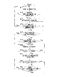
[Fig. 2] is a flow chart showing operation during a warming operation time of
an air conditioner according to an embodiment of the present invention.
Description of Embodiments
[0020]
Hereinafter, an embodiment of the present invention is described with
reference to the drawings. Fig. 1 is a circuit diagram showing a refrigeration
cycle of
an air conditioner according to an embodiment. An air conditioner 1 has an
indoor
apparatus 10 disposed indoors and an outdoor apparatus 20 disposed outdoors.
In the
air conditioner 1, a compressor 21, which flows a refrigerant in a refrigerant
pipe 2
and operates the refrigeration cycle, is disposed in the outdoor apparatus 20.
[0021] The outdoor apparatus 20 is provided therein with: a four-way
valve 22
connected to the compressor 21; an outdoor heat exchanger 23; an expansion
valve 24;
and an outdoor fan 25. The indoor apparatus 10 is provided therein with: an
indoor
CA 02811870 2013-08-09
- 8 -
heat exchanger 13; and an indoor fan 15. The compressor 21 is connected to one
end
of the outdoor heat exchanger 23 and one end of the indoor heat exchanger 13
via the
four-way valve 22 by means of the refrigerant pipe 2. The other ends of the
outdoor
heat exchanger 23 and indoor heat exchanger 13 are connected to each other via
the
expansion valve 24 by means of the refrigerant pipe 2.
[0022]
The outdoor fan 25 is disposed to oppose the outdoor heat exchanger 23. By
driving the outdoor fan 25, outdoor air is supplied to the outdoor heat
exchanger 23,
whereby a heat exchange between the outdoor heat exchanger 23 and the outdoor
air is
prompted. The air performing the heat exchange with the outdoor heat exchanger
23 is
exhaled to outside via an air outlet (not shown) that faces the outdoor fan 25
and opens
from the outdoor apparatus 20.
[0023] The indoor fan 15 and the indoor heat exchanger 13 are disposed
in an airflow
path (not shown) formed in the indoor apparatus 10. By driving the indoor fan
15,
indoor air flows into the airflow path to be supplied to the indoor heat
exchanger 13,
whereby a heat exchange is performed between the air flowing in the airflow
path and
the indoor heat exchanger 13. The air performing the heat exchange with the
indoor
heat exchanger 13 is sent into the room via an air output opening (not shown)
that
opens from the indoor apparatus 10.
[0024]
The outdoor heat exchanger 23 is provided with an outdoor heat exchanger
temperature sensor 26 that detects temperature of the outdoor heat exchanger
23.
Besides, the refrigerant pipe 2 at an output side of the compressor 21 is
provided with
an output temperature sensor 27 that detects an output temperature of the
refrigerant.
The indoor heat exchanger 13 is provided with an indoor heat exchanger
temperature
CA 02811870 2013-08-09
- 9 -
sensor 16 that detects temperature of the indoor heat exchanger 13.
[0025] During a warming operation time, the indoor fan 15 and the
outdoor fan 25 are
driven and the four-way valve 22 is switched as shown by a solid line in the
figure. In
this way, by driving the compressor 21, the refrigerant flows in a direction
indicated
by an arrow A, and the refrigerant, which is compressed by the compressor 21
to have
a high temperature and high pressure, radiates heat in the indoor heat
exchanger 13
and condenses.
[0026] The
high-temperature refrigerant is expanded by the expansion valve 24 to
have a low temperature and low pressure, and sent to the outdoor heat
exchanger 23.
The refrigerant flowing into the outdoor heat exchanger 23 absorbs heat and
evaporates to turn into a low-temperature gas refrigerant and is sent to the
compressor
21. In this way, the refrigerant circulates and the refrigeration cycle is
operated. The
air, performing the heat exchange with the indoor heat exchanger 13 that forms
a high-
temperature portion of the refrigeration cycle, is sent out into the room by
the indoor
fan 15, whereby the indoor warming is performed. Besides, the air, performing
the
heat exchange with the outdoor heat exchanger 23 that form a low-temperature
portion
of the refrigeration cycle, is exhaled to outside by the outdoor fan 25.
[0027]
During a cooling operation time, the indoor fan 15 and the outdoor fan 25 are
driven and the four-way valve 22 is switched as shown by a broken line in the
figure.
In this way, by driving the compressor 21, the refrigerant flows in a
direction opposite
to the arrow A direction, whereby the indoor heat exchanger 13 forms a low-
temperature portion of the refrigeration cycle, while the outdoor heat
exchanger 23
forms a high-temperature portion of the refrigeration cycle. The air,
performing the
CA 02811870 2013-08-09
- 10 -
heat exchange with the indoor heat exchanger 13, is sent into the room by the
indoor
fan 15, whereby the indoor cooling is performed. Besides, the air, performing
the heat
exchange with the outdoor heat exchanger 23 which forms a high temperature
portion
of the refrigeration cycle, is exhaled to outside by the outdoor fan 25.
[0028] Fig. 2 is a
flow chart showing detailed operation during the warming operation
time of the air conditioner 1. If an instruction for starting the warming
operation is
issued, in a step #11, the indoor fan 15, the outdoor fan 25 and the
compressor 21 are
driven to perform the warming operation. In this way, the refrigerant flows in
the
arrow A direction. In a step #12, based on detection by the outdoor heat
exchanger
temperature sensor 26, it is determined whether the outdoor heat exchanger 23
has a
temperature lower than a predetermined temperature because of frost or not .
[0029] In a case where the outdoor heat exchanger 23 does not have a
temperature
lower than the predetermined temperature, back to the step #11, and the steps
#11 and
#12 are repeated. If the outdoor heat exchanger 23 has a temperature lower
than the
predetermined temperature, in a step #13, a defrosting operation is performed.
[0030] During the defrosting operation, the indoor fan 15 and the
outdoor fan 25 are
stopped, and the four-way valve 22 is switched as shown by a broken line in
Fig. 1. In
this way, the refrigerant flows in the direction opposite to the arrow A
direction,
whereby the outdoor heat exchanger 23 forms the high-temperature portion of
the
refrigeration cycle to be raised in temperature. During this time, thanks to
the stopping
of the outdoor fan 25, the heat exchange between the outdoor heat exchanger 23
and
outdoor air is prevented, whereby it is possible to efficiently raise the
temperature of
the outdoor heat exchanger 23. Besides, thanks to the stopping of the indoor
fan 15, it
CA 02811870 2013-08-09
- 11 -
is possible to prevent low-temperature air from being sent out into the room.
[0031] In
a step #14, based on the detection by the outdoor heat exchanger
temperature sensor 26, it is determined whether the outdoor heat exchanger 23
is
raised to a temperature higher than the predetermined temperature or not. In a
case
where the outdoor heat exchanger 23 is not raised to a temperature higher than
the
predetermined temperature, the process moves to a step #15. In the step #15,
it is
determined whether a predetermined time span passes after the defrosting
operation is
started or not. In a case where the predetermined time span passes after the
defrosting
operation is started, it is determined to be defective defrosting, and the
process moves
to a step #17. In a case where the predetermined time span does not pass after
the
defrosting operation is started, the process moves to a step #16.
[0032] In
the step #16, based on detection by the output temperature sensor 27, it is
determined whether the output temperature of the refrigerant declines below a
predetermined temperature (20 C in the present embodiment) or not. In a case
where
the output temperature of the refrigerant declines below the predetermined
temperature, it is determined to be the defective defrosting, and the process
moves to
the step #17. In a case where the output temperature of the refrigerant does
not decline
below the predetermined temperature, back to the step #14, and the steps #14
to #16
are repeated. And, in the step #14, in a case where the outdoor heat exchanger
23 is
raised to a temperature higher than the predetermined temperature, it is
determined
that the defrosting is completed, back to the step #11, and the steps #11 to
#14 are
repeated.
[0033] If
it is determined to be the defective defrosting in the step #15 and the step
CA 02811870 2013-08-09
,
- 12 -
#16, the defrosting operation is ended and the warming operation is performed
in the
step #17. In a step #18, the process waits until the warming operation started
in the
step #17 is performed for a predetermined time span (6 minutes in the present
embodiment). During the defective defrosting, the outdoor heat exchanger 23 is
prevented to be raised in temperature by outdoor low-temperature air, whereby
temperature of the refrigerant flowing in the refrigeration cycle declines.
Because of
this, it is possible to raise the temperature of the refrigerant flowing in
the refrigeration
cycle by means of the warming operation. Besides, by performing the warming
operation for the predetermined time after the defrosting operation, it is
possible to
prevent an indoor temperature decline.
[0034] If the warming operation is performed for the predetermined time
span, the
process moves to a step #19, and a defrosting preparation operation is
performed.
During the defrosting preparation operation, the indoor fan 15 is stopped from
the
state of the warming operation. Specifically, the four-way valve 22 is
switched as
shown by the solid line in Fig. 1, the compressor 21 and the outdoor fan 25
are driven,
and the indoor fan 15 is stopped. In this way, the refrigerant flows in the
same
direction (arrow A direction) as the warming operation, and the temperature
raising of
the refrigerant is continuously performed. During this time, by stopping the
indoor fan
15, it is possible to prevent the heat exchange between the indoor air and the
indoor
heat exchanger 13 that is the high-temperature portion of the refrigeration
cycle and to
raise the temperature of the refrigerant higher than during the warming
operation time.
[0035] In a step #20, it is determined whether a predetermined time
span (3 minutes in
the present embodiment) passes after the defrosting preparation operation is
started or
CA 02811870 2013-08-09
' = .
- 13 -
not. In a case where the predetermined time span does not pass after the
defrosting
preparation operation is started, the process moves to a step #21. In the step
#21, it is
determined based on detection by the indoor heat exchanger temperature sensor
16
whether the indoor heat exchanger 13 is raised to a temperature higher than a
predetermined temperature (56 C or higher in the present embodiment) or not.
In a
case where the indoor heat exchanger 13 is not raised to a temperature higher
than the
predetermined temperature, the steps #20 and #21 are repeatedly performed.
[0036] In a case where it is determined in the step #20 that the
predetermined time
span passes after the defrosting preparation operation is started, or in a
case where it
is determined in the step #21 that the indoor heat exchanger 13 is raised to a
temperature higher than the predetermined temperature, back to the step #13,
and the
defrosting operation is resumed. In this way, the refrigerant, which is raised
in
temperature by the warming operation in the step #17 and by the defrosting
preparation operation in the step #19, flows to perform the defrosting
operation again.
Accordingly, it is possible to surely remove the frost on the outdoor heat
exchanger 23
by means of the resumed defrosting operation and to reduce the defective
defrosting.
[0037] In the meantime, setting the temperature of the indoor heat
exchanger 13,
which is used to determine the end of the defrosting preparation operation in
the step
#21, at 56 C, the pressure in a case where the R410A is used as the
refrigerant is
equivalent to 3.5 MPa-abs. Because of this, considering a time lag from the
detection
of the temperature rise of the indoor heat exchanger 13 to the switching to
the
defrosting operation and a detection error of the indoor heat exchanger
temperature
sensor 16, it is a safe pressure within the specification range.
CA 02811870 2013-08-09
. ,
- 14 -
[0038] Besides, it is also conceivable to use the output temperature
from the
compressor 21 as a criterion for determining the temperature rise of the
indoor heat
exchanger 13. However, it is very hard to predict the pressure based on the
output
temperature, and the pressure is likely to exceed the specification range.
Accordingly,
in the present embodiment, the detected temperature by the indoor heat
exchanger
temperature sensor 16 is used.
[0039] According to the present embodiment, at the defective
defrosting, the
refrigerant is flowed in the same direction (arrow A direction) as the warming
operation and the outdoor fan 25 is driven to perform the defrosting
preparation
operation for the predetermined period with the indoor fan 15 stopped,
thereafter, the
defrosting operation is resumed, accordingly, the refrigerant raised in
temperature by
the defrosting preparation operation is flowed to resume the defrosting
operation. In
this way, the defective defrosting at the resumption time of the defrosting
operation is
reduced, and it is possible to move to the warming operation as soon as
possible so as
to perform the indoor warming and to prevent the malfunction of the outdoor
apparatus 20 caused by the frost growth. Accordingly, it is possible to
improve the
convenience and reliability of the air conditioner 1.
[0040]
Besides, the warming operation is performed for the predetermined period in
the step #17 before the defrosting preparation operation, accordingly, it is
possible to
prevent the indoor temperature decline. In the meantime, the steps #17 and #18
may
be skipped to immediately perform the defrosting preparation operation at the
defective defrosting time. In this way, it is possible to raise the
refrigerant temperature
more rapidly and to rapidly resume the defrosting operation.
CA 02811870 2013-08-09
- 15 -
[0041] Besides, the process moves to the step #13 in the case (step #20)
where the
predetermined time span passes after the defrosting preparation operation is
started,
accordingly, it is possible to perform the defrosting preparation operation
until the
refrigerant is sufficiently raised in temperature, thereafter, to resume the
defrosting
operation.
[0042] Besides, the process moves to the step #13 in the case (step #21)
where the
temperature of the indoor heat exchanger 13 rises to a temperature higher than
the
predetermined temperature during the defrosting preparation operation,
accordingly, it
is possible to rapidly resume the defrosting operation.
[0043] Besides, in the case (step #15) where the temperature of the outdoor
heat
exchanger 23 does not rise to a temperature higher than the predetermined
temperature
even if the predetermined time span passes after the defrosting operation is
started, or
in the case (step #16) where the output temperature of the refrigerant from
the
compressor 21 during the defrosting operation declines below the predetermined
temperature, it is determined to be the defective defrosting, accordingly, it
is possible
to easily determine the defective defrosting and end the defrosting operation.
Industrial Applicability
[0044] The present invention is usable for air conditioners that perform a
warming
operation and a defrosting operation.
Reference Signs List
[0045] 1 air conditioner
2 refrigerant pipe
10 indoor apparatus
CA 02811870 2013-08-09
- 16 -
13 indoor heat exchanger
15 indoor fan
16 indoor heat exchanger temperature sensor
20 outdoor apparatus
21 compressor
22 four-way valve
23 outdoor heat exchanger
24 expansion valve
25 outdoor fan
26 outdoor heat exchanger temperature sensor
27 output temperature sensor