Note: Descriptions are shown in the official language in which they were submitted.
CA 02812838 2013-03-27
Heat-conducting and Heat-dissipating Nano-material, Method for Preparation
Thereof and Heat-dissipating System
FIELD OF THE INVENTION
The present invention relates to the technical field of heat-conduction and
heat-dissipation. Specifically, the present invention relates to a method for
preparing a
heat-conducting and heat-dissipating nano-material, the heat-conducting and
heat-dissipating nano-material produced therefrom, and a heat-dissipating
system
comprising the heat-conducting and heat-dissipating nano-material.
BACKGROUND OF THE INVENTION
Light emitting diode (LED) has a great potential of development among solid
light
sources, and receives increasing attention from people by virtue of its
advantages of
long lifespan, firm structure, low energy consumption and flexible appearance
and size.
In recent years, LED lighting devices are becoming inexpensive and thus
gradually
replace traditional lights used in various occasions of illumination. However,
heat
energy emitted from the LED is quite high during use. If such high heat energy
could
not be dissipated sufficiently, the working efficiency and the lifespan of
various
components inside the LED lighting device would be reduced, or some of the
components may even fail to work normally or even melt. Therefore, effective
dissipation of heat energy generated by LED light source is one of the most
important
factors to be considered when a LED light device is designed or implemented.
It is generally known that there are three ways of heat transfer: convection,
conduction and radiation. Presently, the heat-dissipating system used in LED
lighting
devices is designed to include:
1. Convection or forced convention: the number of fins is increased to enlarge
heat dissipation area and therefore reinforce heat convection and heat
conduction effect.
Figure 1 shows a conventional heat sink 1 used in the prior art LED lighting
device. The
heat sink 1 is surrounded by a plurality of fins 2 in spaced relation. The
fins 2 are made
using lathe technology, and also undergo black oxide finish to exhibit heat
dissipation
¨ 1 ¨
CA 02812838 2013-03-27
property of black body radiation. Such a design in heat dissipation results in
a bulky and
heavy LED lighting device, while its heat dissipation capacity is still
limited and the
costs of production and materials are very high.
2. Selection of materials with good heat conduction: for example pure aluminum
with thermal conductivity of 229w/mk or pure copper with thermal conductivity
of
386w/mk may be used.
Presently, some LED lighting devices have a heat dissipating silica gel
applied
between the heat conduction panel and the heat sink. As the silica gel are
prone to
getting dry to turn into grains, the contact surface between the heat
conduction panel
and the heat sink are not in close contact each other, which would increase a
heat
resistance on the contact surface. Accordingly, the heat conduction
performance of
interface between the light source and the heat sink is greatly reduced.
Therefore, it is
impossible to acquire good heat dissipation effect.
In order to enhance the heat dissipation capacity of the LED lighting devices,
the
heat sink may be subject to surface treatment, including but not limited to
anodic
oxidation treatment and black coating treatment. However, these two methods
only
bring limited improvement on the heat dissipation capacity of the heat sink in
the LED
lighting device, particularly in the LED lighting device with high power.
Nanotechnology has found a wide range of applications as a new technology in
recent years. The nano-materials are well known for their surface effect,
volume effect
and quantum size effect, and exhibit many outstanding physical and chemical
properties,
for example in aspects of melting point, electrical conductivity, thermal
conductivity etc.
There have been a large number of teachings on the use of nano-materials as
heat-conducting and heat-dissipating materials. However, the problem of even
dispersion of nano-particles, especially nano-particles with particle size
less than mm,
in a solvent remains.
In general, the prior art LED lighting devices are very bulky and require
labor-intensive manufacturing procedures because their heat dissipation
structures are
quite bulky and complicated. Therefore, there is a need for improvement on the
heat-dissipating system of the LED lighting devices. The present invention
introduces a
novel heat-dissipating system taking advantage of nano-materials, which not
only
- 2 -
CA 02812838 2013-03-27
improves the heat dissipation efficiency but also allows the lighting devices
to work in a
stable condition while implementing a compact and light structure at a low
cost.
SUMMARY OF THE INVENTION
It is the inventors' finding that simultaneous use of tert-butyl acetate
(CAS#540885) and 4-Chlorobenzotrifluoride (CAS#98566) as dispersants enables
even
dispersion of nano-particles with particle size less than 1 nm in the water-
soluble
solvent such as water so as to afford an emulsion which has particularly
excellent
performance in heat conduction and heat dissipation.
Based on the above finding, the present invention proposes a new process for
preparation of a heat-conducting and heat-dissipating nano-material. The
resultant
heat-conducting and heat-dissipating nano-material has the ability of
effectively and
quickly dissipating the heat generated inside the LED lighting device. Due to
its
excellent heat dissipation effect, the size of heat dissipation structure can
be very smallõ
the heat dissipation fins commonly used in the art can even be removed. As a
result, the
whole lighting device becomes smaller and lighter.
In order to achieve the above objects, the present invention provides a method
for
preparation of a heat-conducting and heat-dissipating nano-material,
characterized by
comprising the following steps:
i) mixing a complex formed by a high molecular material and a substance
having heat conduction and heat dissipation properties with tert-butyl acetate
and
4-Chlorobenzotrifluoride, wherein the complex is of nanoscale in particle
size; and
ii) placing the mixture obtained from step i) into water and stirring the
mixture in
water for a period of time to afford the heat-conducting and heat-dissipating
material.
According to the present invention, the substance having heat conduction and
dissipation properties may be inorganic or organic, and may be selected from
the group
consisting of ceramic, carbon, paraffin, silica and polymethylsilazane.
Preferably, the complex, the tert-butyl acetate and the 4-
Chlorobenzotrifluoride are
mixed in a ratio by weight of the complex 20-40%: the tert-butyl acetate 35-
45%: the
4-Chlorobenzotrifluoride 25-35%. Based on a total weight of water, the
complex, the
- 3 -
CA 02812838 2013-03-27
tert-butyl acetate and the 4-Chlorobenzotrifluoride, the water is used in an
amount of
about 25-75% weight of the total weight.
The particle size of the complex used in the invention is less than lnm.
In step ii), the stirring is performed at an atmospheric pressure and at room
temperature for 10-20 minutes. The heat conducting and heat dissipating
material is
then formed as an emulsion.
A second aspect of the invention relates to a heat-conducting and heat-
dissipating
nano¨material prepared by a method of the invention.
A third aspect of the invention provides a heat dissipating system for a
lighting
device, comprising a heat conduction panel connected with a light source in a
thermally
conductive manner, and a heat sink heat sink connected with the heat
conduction panel
for heat conduction, the heat-conducting and heat-dissipating nano-material of
the
invention is applied onto a surface of the heat conduction panel in contact
with the heat
sink, and/or onto an external surface of the heat sink.
In one preferred embodiment of the invention, the heat-conducting and
heat-dissipating nano-material applied onto the surface of the heat conduction
panel in
contact with the heat sink is 0.3-2 mil in thickness, and the heat-conducting
and
heat-dissipating nano-material applied onto the external surface of the heat
sink is 0.3-2
mil in thickness.
In order to ensure that the surfaces are sufficiently clean for the
application of the
heat-conducting and heat-dissipating material for enhanced attachment and
prolonged
lifespan of the material, the heat conduction panel and the heat sink are pre-
treated by
sand blast before the application of the material.
In one embodiment of the invention, the light source is one or more LEDs.
In another embodiment of the invention, the heat sink is free of heat-
dissipating
fins or provided with a small number of fins. The heat conduction panel and
the heat
sink are made from metal.
Depending on which type of substance having properties of heat conduction and
heat dissipation is used, the heat-conducting and heat-dissipating nano-
material of the
invention varies in its heat conduction performance and heat dissipation
performance.
- 4 -
CA 02812838 2013-03-27
For example, the heat-conducting and heat-dissipating material made from the
complex
formed by high molecular material and ceramic would have better heat
conductivity,
which is more suitable to be coated between the heat conduction panel and the
heat sink
to transfer the heat generated by the LED light source to the heat sink by
heat
conduction and also by heat radiation as a supplementary means. The heat-
conducting
and heat-dissipating material made from the complex formed by high molecular
material and silica would have better performance in heat dissipation, which
is more
suitable to be coated on the external surface of the heat sink so as to
transfer the heat to
the ambient by the way of radiation.
The heat-conducting and heat-dissipating nano-material of the present
invention is
viscous, and can be naturally cured within half an hour. This allows the
material to
adhere the heat conduction panel and heat sink together.
The heat-conducting and heat-dissipating material of the present invention is
of
nano-particles, particularly nano-particles with sizes less than 1 nm, they
can be easily
and evenly dispersed in the water-soluble solvent in the presence of both tert-
butyl
acetate and 4-Chlorobenzotrifluoride used as the dispersing agents to give a
homogenous emulsion. The present invention has not only solved the problems of
even
dispersion of the nano-particles in the solvent, but also acquired the
emulsion with
excellent performance in heat conduction and heat dissipation. It is found
that coating of
this emulsion between the heat conduction panel and the heat sink as well as
on the
external surface of the heat sink can transfer quickly the heat generated by
the LED
light source to the surface of the heat sink through heat conduction or heat
convection,
and the heat is then dissipated from the heat sink to the ambient by heat
radiation,
thereby conferring the active heat dissipation ability on the heat sink. Since
the
nano-material of the present invention has greatly increased the heat
dissipation
efficiency of the LED light, in some cases the fins may be removed from the
heat sink.
Such a heat sink thus has simple structure with light weight and small size,
and the cost
on raw materials can be reduced significantly.
As stated above, depending on which type of substance having properties of
heat
conduction and heat dissipation is used, the heat-conducting and heat-
dissipating
nano-material of the invention varies in its heat conduction performance and
heat
dissipation performance. The material selected for the coating between the
heat
¨
CA 02812838 2013-03-27
conduction panel and the heat sink preferably has better heat conductivity and
therefore
the heat-conducting and heat-dissipating material made from the complex formed
by
high molecular material and ceramic may be used. The material selected for the
coating
on the surface of the heat sink preferably has better performance in heat
dissipation, and
therefore the heat-conducting and heat-dissipating material made from the
complexes
formed by high molecular material and silica may be used.
The following paragraphs will further illustrate and explain the
conceptions,
structures and technical effects of the present invention with reference to
the drawings,
so as to allow for a better understanding of the objects, features and effects
of the
present invention.
BRIEF DESCRIPTION OF THE DRAWINGS
The further objects, features, characteristics and effects of the invention
will be
illustrated in more details by way of examples with reference to the accompany
drawings, wherein:
FIG. 1 is a schematic view of a heat sink adopted by an existing LED lighting
device;
FIG. 2 is a schematic view of a heat-dissipating system of a LED lighting
device
according to an embodiment of the present invention;
FIG. 3 is a schematic view of a heat sink according to an embodiment of the
present invention.
DETAILED DESCRIPTION OF THE PREFERRED EMBODIMENTS
For illustrative purpose, two heat-conducting and heat-dissipating nano-
materials
according to the invention are prepared respectively using water-soluble high
molecular
ceramic complex with particle size smaller than 1 nanometer (nm) and water-
soluble
high molecular silica complex with particle size smaller than 1 nanometer (nm)
as raw
materials.
- 6 -
CA 02812838 2013-03-27
The commercially available water-soluble high molecular ceramic complex (from
a variety of commercial sources) is mixed with tert-butyl acetate (CAS#540885)
and
4-Chlorobenzotrifluoride (CAS#98566) at a predetermined ratio, the mixture is
placed
into water and stirred for about 10-20 minutes at room temperature and
atmospheric
pressure, the desired heat-conducting and heat-dissipating nano-material is
then formed
as a homogenous viscous emulsion.
The high molecular ceramic complex, tert-butyl acetate (CAS#540885) and
4-Chlorobenzotrifluoride (CAS#98566) are mixed at the following ratio by
weight:
High molecular ceramic complex: 20-40%
Tert-butyl acetate: 35-45%
4-Chlorobenzotrifluoride: 25-35%
The amount of water used can be 25-75% of the total weight of water and the
above three substances.
According to one embodiment of the invention, 30% weight of the high molecular
ceramic complex, 35% weight of tert-butyl acetate (CAS#540885) and 35% weight
of
4-Chlorobenzotrifluoride (CAS#98566) are mixed, and the mixture is placed in
water
and stirred to afford water-soluble high molecular ceramic emulsion. This
emulsion is
tested for its typical properties which are given as below:
1. Viscosity: 15 seconds measured at 25 C by Brookfield 7# testing method;
2. Density: 2.70-2.71g/cm3 measured at 25 C;
3. Working temperature: -40 C to +200 C;
4. Heat conductivity coefficient: 8W/Mk measured according to ASTM D5470;
5. Dielectric strength: 305V/mil measured according to ASTM D 149;
6. Volume resistivity: 1.65X10I4ohm-cm measured according to ASTM D257;
7. Bleed reliability: 0.005% measured at 200 C for 24 hours;
8. Reliability of evaporation capacity: 0.5% measured at 200 C for 24
hours;
9. Decomposition temperature for 2 hours: 400 C, and
-7.--
CA 02812838 2013-03-27
10. Heat radiation efficiency: 10% at heat dissipation speed AT4 at 25 C.
As can be seen, the water-soluble high molecular ceramic of the present
invention
has a higher heat conductivity coefficient, while its thickness may be made
very thin,
for example about lp.m. By contrast with conventional heat conductors which
have a
thickness in millimeter scale, the water-soluble high molecular ceramic of the
present
invention is of a reduced significantly thickness, making it possible that the
material is
used as an excellent heat conductor.
The above high molecular ceramic emulsion can be directly applied on the heat
conduction panel configured in the LED lighting device. Due to its mobility,
the
emulsion tends to flow into gaps among the components and forms a thin dense
film
after solidification. As all the gaps are provided with the dense film, the
efficiencies of
heat conduction and heat convection would be increased. Furthermore, the heat
conduction panel and the heat sink can be adhered together due to the
viscosity of the
emulsion. The emulsion is air dried (for about 20 minutes) and would be cured
to
become a heat conduction coating between the heat conduction panel and the
heat sink.
According to the present invention, the water-soluble high molecular ceramic
may
be provided as a coating in a thickness of preferably 0.3-2mil, and more
preferably
0.5-2mil.
The water-soluble high molecular silica emulsion is prepared in the same way
as
the water-soluble high molecular ceramic emulsion. Specifically, the
commercially
available water-soluble high molecular silica complex having particle size
smaller than
1 nm (from a variety of commercial sources) is mixed with tert-butyl acetate
(CAS#540885) and 4-Chlorobenzotrifluoride (CAS#98566) at a predetermined
ratio,
preferably at the following ratio by weight:
High molecular silica complex: 20-40%
Tert-butyl acetate: 35-45%
4-Chlorobenzotrifluoride: 25-35%
Then, the mixture is placed into water and stirred for about 10-20 minutes at
room
temperature and atmospheric pressure to afford a homogenous viscous emulsion.
The
- 8 -
CA 02812838 2013-03-27
amount of water used can be 25-75% of the total weight of water and the above
three
substances.
According to one embodiment of the invention, the water-soluble high molecular
silica emulsion of the present invention is prepared using 30% weight of high
molecular
silica complex, 35% weight of tert-butyl acetate (CAS#540885) and 35% weight
of
4-Chlorobenzotrifluoride (CAS#98566). This emulsion is tested for its typical
properties which are given as below:
1. Viscocity: 12 seconds measured at 25 C by #2 Zahn Cup testing method;
2. Temperature resistance: 980 C measured by Heat Stability method;
3. Heat radiation efficiency: 30-50% at heat dissipation speed AT4 at 25 C;
abd
4. Decomposition temperature for 2 hours: 1000-1300 C.
As can be seen, the high molecular silica emulsion has an excellent heat
radiation
property and is particularly suitable to be applied as a coating on an
external surface of
the heat sink of LED lighting device, allowing the heat transfer to the
ambient by way
of heat radiation. The high molecular silica emulsion of the present invention
has the
characteristics of heat-insulation, electricity-insulation, rust-resistance,
acid and base
salt-resistance, wear-resistance and the like.
Generally, the high molecular silica emulsion is provided as a coating applied
on
the external surface of the heat sink in a thickness of preferably 0.3-2 mil,
more
preferably 0.5-1 mil. This coating is tested and the results are given as
follows:
-Pencil hardness of the coating: 9H measured according to ASTM D3363;
-Coating firmness: 5B measured according to ASTM D3359;
-Coating distortion: 18mm measured according to ASTM D522;
-Impact Load of the coating: <10 pound measured according to ASTM D2794.
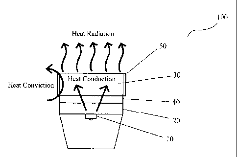
Now referring to Figure 2, there is illustrated a schematic view of heat-
dissipating
system of LED lighting device according to a first embodiment of the present
invention.
The LED lighting device 100 comprises a LED light source 10, a heat conduction
panel
20 supporting the LED light source 10 and in contact with the LED light source
10 in
9
CA 02812838 2013-03-27
thermally conductive manner, and a heat sink 30. The LED light source 10 can
be one
or more LED chips, the heat conduction panel 20 and the heat sink 30 can be
made from
metal such as aluminum. This is not the essence of the present invention, and
therefore
will not be detailed herein. Other structures of the LED lighting device may
be made
reference to the prior art technology and not described either.
The heat dissipating system of the LED lighting device according to the
present
invention is characterized by the application of the heat-conducting and heat-
dissipating
nano-material of the present invention between the heat conduction panel 10
and the
heat sink 30 as well as on the external surface of the heat sink 30. In this
embodiment,
the water-soluble high molecular ceramic emulsion discussed above is applied
between
the heat conduction panel 10 and the heat sink 30, while the water-soluble
high
molecular silica emulsion discussed above is applied on the external surface
of the heat
sink 30. In order to enhance the attachment of the material and extend the
lifespan of the
material, the coating surface is subject to thorough cleaning treatment. For
this purpose,
the heat conduction panel and the heat sink have to be pre-treated by sand
blast.
As shown in Figure 2, the heat conduction panel 20 and the LED light source 10
are secured together in thermally conductive manner, allowing the heat
transfer from the
LED light source 10 to the heat conduction panel 20, and then to the heat sink
30
through the high molecular ceramic coating 40 by way of both heat conduction
and heat
convection. The heat is subsequently dissipated rapidly by the high molecular
silica
coating 50 on the external surface of the heat sink 30.
Figure 3 shows a schematic view of the heat sink 30 constructed according to
the
present invention. As shown in the figure, the external surface of the heat
sink 30 is free
of a heat-dissipating fin, unlike the prior art heat sinks. The heat sink 30
is about 1 mm
in thickness and made from T6063 aluminum alloy by spinning technology. Since
no
heat-dissipating fins are configured, it is possible that the heat sink is
made by spinning,
casting, punching and forging technologies in place of lathe technology, which
simplifies the manufacturing process of the heat sink. Moreover, the
elimination of fins
permits reduction in weight of the heat sink 30 by about 3/4. Furthermore, the
heat sink
30 requires no treatment such as anodic oxidation treatment or black oxide
finish, and
thus the manufacturing cost can be greatly reduced.
A comparison between the prior art heat sink shown in Figure 1 and the heat
sink
¨10---
CA 02812838 2013-03-27
30 of the present invention shown in Figure 3 has been conducted, and the
comparison
results are illustrated in the following table:
Prior art heat sink shown Heat sink of the invention* Effect of the invention
in Figure 1
Appearance of heat Cylindrical: Cylindrical:
sink 0150 X 80mm 0210 X 95mm
Elimination
of
Number of fins 38 0
manufacturing of fins
Wall thickness of 2mm lmm Reduction in wall
thickness
heat sink by a half
Material used ADC12casting aluminum T6063 spinning aluminum Simplification
of
alloy alloy manufacturing
process
Anodic oxidation and Application a coating of high Simplification
of
Surface treatment
black oxide finish molecular silica pre-treatments
Weight 560g 135g Reduction in
weight by 75%
Increase in room temperature
Heat dissipation
Room temperature by 20 C,
suggesting the
efficiency (calculated Room temperature around
around the heat sink: increase in heat
dissipation
by CFD simulation the heat sink: 27 C-65 C
27 C ¨45 C capacity of the
heat sink by
software)
30%
* The tested heat sink has a coating of the water soluble high molecular
ceramic
emulsion applied between the heat conduction panel and the heat sink, and a
coating
of the water soluble high molecular silica emulsion applied on the external
surface of
the heat sink.
The above comparison results revealed that the heat sink of the LED lighting
¨11--
CA 02812838 2013-03-27
device constructed according to the present invention can be thinner and
lighter, and
may require no heat-dissipating fins. So the weight of such a heat sink is at
least
reduced by 40-50% or even 75% compared with the conventional heat sinks having
the
fins. Even no fin is provided on the heat sink of the present invention, its
heat
dissipation capacity is improved by at least 20-30% compared with the
conventional
heat sinks having the fins, if the heat-dissipating and heat-conducting
materials of the
present invention are applied between the heat conduction panel and the heat
sink as
well as on the external surface of the heat sink. Besides, the manufacturing
process of
the heat sink is simplified significantly, and the materials required for
manufacturing the
body of the heat sink and the heat-dissipating fins are reduced as well.
Accordingly, raw
materials can be saved, and the manufacturing cost can be reduced
significantly.
Of course, it is possible to have the heat dissipating fins on the surface of
the heat
sink 30 according to the actual needs, but the number of the fins can be
small. Provision
of the fins on the heat sink of the invention would further enhance the heat
dissipation
effect thereof.
The application of the heat-conducting and heat-dissipating nano-materials
prepared by the method of the present invention in the heat-dissipating system
of LED
lighting device is discussed above. It is understood that such heat-conducting
and
heat-dissipating nano-materials can find applications in other fields and
occasions
which require heat conduction and heat dissipation (such as flat heat sinks in
electronic
structure), with the advantages of excellent heat dissipation effect,
simplified
manufacturing process and reduced manufacturing cost.
While the preferred embodiments are described hereinabove, it will be
appreciated
by those skilled in the art that the present invention is not limited to the
embodiments
illustrated. Those skilled in the art will envision many other possible
variations and
modifications by means of the skilled person's common knowledge without
departing
from the scope of the invention, however, such variations and modifications
should fall
into the scope of this invention.
- 12 -