Note: Descriptions are shown in the official language in which they were submitted.
CA 02813121 2014-12-18
METHODS FOR FORMING A PLASTIC MATCHING LAYER
OF A TRANSDUCER
BACKGROUND
Field
[0001] The various embodiments relate to ultrasonic flow meters and
particularly to
transducers used in ultrasonic meters.
Description of the Related Art
[0002] After hydrocarbons have been removed from the ground, the fluid stream
(either in a
liquid phase or a gaseous phase) is transported from place to place via
pipelines. It is desirable
to know with accuracy the amount of fluid flowing in the stream, and
particular accuracy is
demanded when the fluid is changing hands, or "custody transfer." Even where
custody
transfer is not taking place, however, measurement accuracy is desirable, and
in these situations
ultrasonic flow meters may be used. In an ultrasonic flow meter, ultrasonic
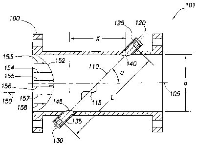
signals are sent back
and forth across the fluid stream to be measured, and based on various
characteristics of the
ultrasonic signals a fluid flow may be calculated. Mechanisms which improve
the quality of the
ultrasonic signals imparted to the fluid may improve measurement accuracy.
Moreover, wear
and tear (e.g., caused by the corrosivity of the fluid being measured) on the
components of the
meter can substantially decrease longevity of the device, and thus any method
to increase the
durability of the meter and its components would be desirable. Finally,
ultrasonic flow meters
may be installed in harsh environments, and thus any mechanism to reduce
maintenance time,
and if possible improve performance, would be desirable.
SUMMARY
[0003] The various embodiments are directed to systems and methods of a
transducer having
a plastic matching layer. At least some of the illustrative embodiments are
transducers
comprising a housing (having a proximal end, a distal end and an internal
volume, the housing
configured to couple to a spoolpiece of an ultrasonic meter), a plastic
matching layer that has an
external surface and an internal surface (the plastic matching layer seals to
and occludes the
distal end of the housing), and a transducer element abutting the internal
surface of the plastic
matching layer.
[0004] Other illustrative embodiments are ultrasonic meters comprising a
spoolpiece having
an internal flow path for a measured fluid, and a transducer in operational
relationship to the
spoolpiece. The transducer further comprises a housing that defines an
internal volume, a
- 1 -
CA 02813121 2013-04-15
plastic matching layer that separates the internal volume of the housing from
the measured fluid
(wherein the plastic matching layer has an acoustic impedance between that of
a piezoelectric
crystal and the measured fluid), and a transducer element abutting an internal
surface of the
plastic matching layer.
[0005] Yet still other illustrative embodiments are methods comprising
generating an
ultrasonic signal, propagating the ultrasonic signal through a plastic
matching layer, and
imparting the acoustic signal to a fluid within an ultrasonic meter.
[0006] Finally, other embodiments are methods comprising providing a
transducer housing
having a proximal end and a distal end, bonding a plastic to the distal end of
the transducer
housing (the plastic fluidly sealing and occluding the distal end). The
bonding further
comprises inserting a cylinder at least partially coated with a mold-release
chemical into the
transducer housing, bonding plastic onto the distal end of the transducer
housing, and removing
the cylinder when the plastic has hardened.
BRIEF DESCRIPTION OF THE DRAWINGS
[0007] For a more detailed description of embodiments, reference will now be
made to the
accompanying drawings, in which:
[0008] Figure IA is an elevational cross-sectional view of an ultrasonic flow
meter;
[0009] Figure 1B is an elevational end view of a spoolpiece which
illustrates chordal paths A,
B, C and D;
[0010] Figure 1C is a top view of a spoolpiece housing transducer pairs;
[0011] Figure 2 is a perspective view of a transducer in accordance with
various
embodiments;
[0012] Figure 3 is a cross-sectional elevation view of a transducer in
accordance with various
embodiments;
[0013] Figure 4 is a cross-sectional elevation view of a transducer with
interior structures
not present and prior to molding of the plastic;
[0014] Figure 5 (comprising Figures 5A, 5B and 5C) is a cross-sectional
elevation view of a
transducer after a plastic matching layer has been molded to the distal end;
[0015] Figure 6 is a cross-sectional elevation view of a transducer after a
plastic matching
layer has been machined;
[0016] Figure 7 is a flow diagram in accordance with various embodiments of
the invention;
and
[0017] Figure 8 is a flow diagram in accordance with various embodiments.
- 2 -
,
CA 02813121 2013-04-15
NOTATION AND NOMENCLATURE
[0018] Certain terms are used throughout the following description and claims
to refer to
particular system components. This document does not intend to distinguish
between
components that differ in name but not function.
[0019] In the following discussion and in the claims, the terms "including"
and
"comprising" are used in an open-ended fashion, and thus should be interpreted
to mean
"including, but not limited to. Also,
the term "couple" or "couples" is intended to mean
either an indirect or direct connection. Thus, if a first device couples to a
second device, that
connection may be through a direct connection, or through an indirect
connection via other
devices and connections.
[0020] "Fluid" shall mean a liquid (e.g., crude oil or gasoline) or a gas
(e.g., methane).
DETAILED DESCRIPTION
[0021] Figure lA is a cross-sectional elevation view of an ultrasonic meter
101 in accordance
with various embodiments. Spoolpiece 100, suitable for placement between
sections of a
pipeline, is the housing for the meter 101. The spoolpiece 100 has an internal
volume that is a
flow path for a measured fluid and also has a predetermined size that defines
a measurement
section within the meter. A fluid may flow in a direction 150 with a velocity
profile 152.
Velocity vectors 153-158 illustrate that the fluid velocity through spoolpiece
100 increases
toward the center.
[0022] Transducers 120 and 130 are located on the circumference of the
spoolpiece 100.
The transducers 120 and 130 are accommodated by transducer ports 125 and 135,
respectively.
The position of transducers 120 and 130 may be defined by the angle 0, a first
length L
measured between transducers 120 and 130, a second length X corresponding to
the axial
distance between points 140 and 145, and a third length "d" corresponding to
the pipe diameter.
In most cases distances d, X and L are precisely determined during meter
fabrication. Further,
transducers such as 120 and 130 may be placed at a specific distance from
points 140 and 145,
respectively, regardless of meter size (i.e. spoolpiece size). Although the
transducers are
illustrated to be recessed slightly, in alternative embodiments the
transducers protrude into the
spoolpiece.
[0023] A path 110, sometimes referred to as a "chord," exists between
transducers 120 and
130 at an angle 0 to a centerline 105. The length L of "chord" 110 is the
distance between the
face of transducer 120 and the face of transducer 130. Points 140 and 145
define the locations
-3 -
CA 02813121 2013-04-15
where acoustic signals generated by transducers 120 and 130 enter and leave
fluid flowing
through the spoolpiece 100 (i.e. the entrance to the spoolpiece bore).
[0024] Transducers 120 and 130 are preferably ultrasonic transceivers, meaning
that they
both generate and receive ultrasonic signals. "Ultrasonic" in this context
refers to frequencies
above about 20 kilohertz. To generate an ultrasonic signal, a piezoelectric
element is
stimulated electrically, and it responds by vibrating. The vibration of the
piezoelectric element
generates an ultrasonic signal that travels through the fluid across the
spoolpiece to the
corresponding transducer of the transducer pair. Similarly, upon being struck
by an ultrasonic
signal, the receiving piezoelectric element vibrates and generates an
electrical signal that is
detected, digitized, and analyzed by electronics associated with the meter.
Initially,
downstream transducer 120 generates an ultrasonic signal that is then received
by upstream
transducer 130. Some time later, the upstream transducer 130 generates a
return ultrasonic
signal that is subsequently received by the downstream transducer 120. Thus,
the transducers
120 and 130 play "pitch and catch" with ultrasonic signals 115 along chordal
path 110. During
operation, this sequence may occur thousands of times per minute.
[0025] The
transit time of the ultrasonic signal 115 between transducers 120 and 130
depends in part upon whether the ultrasonic signal 115 is traveling upstream
or downstream
with respect to the fluid flow. The transit time for an ultrasonic signal
traveling downstream
(i.e. in the same direction as the flow) is less than transit time when
traveling upstream (i.e.
against the flow). The upstream and downstream transit times can be used to
calculate the
average flow velocity along the signal path, and may also be used to calculate
the speed of
sound in the fluid. Knowing the cross-sectional area of the meter carrying the
fluid and
assuming the shape of the velocity profile, the average flow velocity over the
area of the meter
bore may be used to find the volume of fluid flowing through the meter 101.
[0026] Ultrasonic flow meters can have one or more pairs of transducers
corresponding to
one or more paths. Figure 1B is an elevation end-view of a spoolpiece 100. In
these
embodiments, spoolpiece 100 comprises four chordal paths A, B, C, and D at
varying levels
through the fluid flow. Each chordal path A-D corresponds to two transducers
behaving
alternately as a transmitter and receiver. Also shown are control electronics
160, which acquire
and process data from the four chordal paths A-D. Hidden from view in Figure
1B are the four
pairs of transducers that correspond to chordal paths A-D.
[0027] An arrangement of the four pairs of transducers may be further
understood by
reference to Figure 1C, showing spool piece 100 and flow direction 150. Each
pair of
transducer ports corresponds to a single chordal path of Figure 1B. A first
pair of transducer
- 4
CA 02813121 2013-04-15
ports 125 and 135, mounted at a non-perpendicular angle 0 to centerline 105 of
spool piece 100,
houses transducers 120 and 130 (Figure 1A). Another pair of transducer ports
165 and 175
(only partially in view) houses associated transducers so that the chordal
path loosely forms an
"X" with respect to the chordal path of transducer ports 125 and 135.
Similarly, transducer
ports 185 and 195 may be placed parallel to transducer ports 165 and 175 but
at a different
"level" (i.e. a different elevation in the spoolpiece). Not explicitly shown
in Figure 1C is a
fourth pair of transducers and transducer ports. Taking Figures 1B and 1C
together, the pairs of
transducers are arranged such that the upper two pairs of transducers
corresponding to chords A
and B, and the lower two pairs of transducers corresponding to chords C and D.
The flow
velocity of the fluid may be determined at each chord A-D to obtain chordal
flow velocities, and
the chordal flow velocities combine to determine an average flow velocity over
the entire pipe.
Although four pairs of transducers are shown forming an X shape, there may be
more or less
than four pairs. Also, the transducers could be in the same plane or in some
other configuration.
[0028] Figure 2 is a perspective view of a transducer 210 in accordance with
various
embodiments. The transducer 210 comprises a cylindrical housing 211, which in
some
embodiments is metal (e.g., low carbon stainless steel). In alternative
embodiments, any
material capable of withstanding the pressure of the fluid within the meter,
such as high
density plastics or composite materials, may be equivalently used. The
transducer 210
comprises a distal end 212 and a proximal end 214. The distal end 212 is
occluded and
sealed by a plastic matching layer 216. Threads 218 on the outside diameter of
the transducer
housing 210 near the proximal end 214 enable the transducer 210 to be coupled
to the
spoolpiece 100 (Figures 1A-C), and an o-ring with groove 220 seals the
transducer 210 to the
transducer port (Figures 1A-C). In alternative embodiments, the transducer 210
is welded to
the transducer port (Figures IA-C) of the spoolpiece, and thus the threads 218
and grove 220
may be omitted.
[0029] Figure 3 is a cross-sectional elevation view of a transducer 210 in
accordance with
various embodiments. In particular, the housing 211, may, in some embodiments,
comprise two
individual components. For example, the distal end 212 of the transducer 210
may comprise a
first cylindrical outer housing 302, and the proximal end 214 may comprise a
second
cylindrical outer housing 304 (comprising the threads 218), where the two
housings 302, 304
are bonded together as part of the construction process. In alternative
embodiments, the
cylindrical outer housing 211 may comprise a single piece structure, where the
various
components are installed through one end.
-5 -
,
CA 02813121 2013-04-15
[0030] The plastic matching layer 216 occludes the distal end 212 and defines
an exterior
surface 310 and an interior surface 312. More particularly, the housing 211
defines a
circumference around which the plastic matching layer 216 is molded. In some
embodiments,
the housing 211 comprises circumferential bonding ridges 318 to which the
plastic bonds. In
alternative embodiments, the housing 211 comprises circumferential bonding
grooves (Figure
5), again to which the plastic bonds. The exterior surface 310 of the plastic
matching layer 216
is exposed to fluids flowing through the spoolpiece/meter (Figures 1A-C), and
the interior
surface 312 abuts a transducer element 314 (e.g., a piezoelectric element).
The volume behind
the transducer element 314 comprises a back matching layer 316 and back
matching support
layer 324. The back matching layer 316 may be, for example, plastic, metal,
glass, ceramic,
epoxy, powder-filled epoxy, rubber, or powder-filled rubber. In some
embodiments, the
transducer element 314 is biased towards the plastic matching layer 216 by way
of a conic
washer 326, but any biasing system (e.g., coil springs) may be equivalently
used. Biasing the
transducer element 314 toward the plastic matching layer 216 helps ensure good
acoustic
coupling of the transducer element 314 to the plastic matching layer 216, and
further provides
structural support for the plastic matching layer 216 by reducing inward
deflection of the plastic
matching layer caused by high fluid pressures within the meter.
[0031] Still referring to Figure 3, on the proximal end 214 of the housing 211
is a pin recess
328 within which resides two connection pins 321 and 322. The two connection
pins 321, 322
are arranged at the desired spacing and exposed to enable the pins to couple
to the external
electronics of the meter by way of a cable. Interior of the transducer 210 the
pins mate with the
connector 320 within the back matching support layer 324, which connector 320
provides an
electrical coupling of the pins 321, 322 to the transducer element 314. In
some embodiments,
the pins 321, 322 seal to the housing 211 (in area 325), such as by a glass-to-
metal seal. The
sealing of the pins 321, 322 along with the seal provided by the plastic
matching layer 216
isolates the internal components of the transducer 210 both from the fluid and
meter and
atmosphere. In the event the seal provided by the plastic matching layer
fails, the sealing of the
pins 321, 322 reduces the possibility of escape of fluid in the meter through
the transducer. The
level of protection provided by sealing the pins against escape of the fluid
through the
transducer is particularly important in situations where the fluid in the
meter contains poisonous
substances (e.g., the fluid is a hydrocarbon stream containing hydrogen
sulfide).
[0032] In addition to sealing an interior volume of the transducer 210 from
fluids in the
meter, the plastic matching layer 216 provides acoustical coupling between the
transducer
element 314 and fluid in the meter. In accordance with the various
embodiments, the plastic
- 6 -
CA 02813121 2013-04-15
matching layer has acoustic impedance between that of the transducer element
314 and fluid
in the meter. With the acoustic impedance of the matching layer between that
of the
transducer element and the fluid in the meter, the quality of the ultrasonic
signal is improved
(e.g., larger amplitude and faster rise time). In some embodiments the plastic
matching layer
216 is thermoplastic, which is corrosion resistance. Depending on the pressure
to which the
transducer 210 will be exposed and the characteristics of the fluid in the
meter (e.g., how
corrosive), other plastics may be equivalently used. Plastic matching layers
have the desired
acoustic impedance to provide good acoustic coupling while being strong enough
to resist the
pressure of the fluid within the meter so that the transducer element can be
isolated from the
fluid in the within the meter. In some embodiments, the acoustic impedance of
the plastic
matching layer 216 is between about 1 and about 30 Mega-rayl (MRay1), and
particularly
between about 2 and about 4 MRayl. Comparatively, the acoustic impedance of a
matching
layer comprising substantially stainless steel is more than the acoustic
impedance of the
piezoelectric element, and therefore provides poor acoustic coupling.
[0033] The plastic matching layer 216 has a thickness (along an axis shared
with the
remaining portions of the housing 211) that in some embodiments is
substantially equal to an
odd multiple of one-quarter (1/4, 3/4, 5/4, 7/4, etc.) wavelength of the sound
generated by the
transducer element 314. For example, consider a transducer element 314
operating at a
frequency of 125 kHz and a plastic matching layer 216 with a speed of sound of
2,500 m/s.
The wavelength of the sound in the matching layer is approximately 0.788
inches. In these
embodiments the plastic matching layer may be 0.197, 0.590, 0.984, 1.378 and
so on, inches
thick. A thinner plastic matching layer gives better acoustical performance,
but making the
plastic matching layer thicker enables the transducer 210 to withstand higher
pressures.
Picking the optimal matching layer thickness involves choosing the thinnest
matching layer
that can hold the highest pressures expected inside the meter.
[0034] The discussion now turns to various embodiments of constructing a
transducer 210
having a plastic matching layer. In particular, Figure 4 is a cross-sectional
elevation view of a
portion of housing 211, with interior structures not present and prior to
molding of the plastic to
create the plastic matching layer. Before the plastic matching layer is
applied, a telescoping
cylinder 412 having a outside diameter slightly smaller than the inside
diameter 410 of the
housing 211 is inserted into the housing 211. The telescoping cylinder 412 is
at least partially
coated with a mold release chemical to facilitate the removal of the cylinder
after the plastic
matching layer has hardened. In some embodiments (and as shown in Figure 4),
the end of the
telescoping cylinder is recessed slightly from the distal end 212 of the
housing 211, enabling
- 7
CA 02813121 2013-04-15
the plastic to partially fill an interior volume of the housing 211. In
alternative embodiments,
the cylinder 412 maybe positioned such that the end of the cylinder 412 and
the distal end of
the housing 211 form a plane, and thus when formed the plastic of the plastic
matching layer
will not extend any appreciable distance into the interior volume of housing
211.
[0035] After
placing cylinder 412, the plastic is molded to the distal end of the housing
211.
In particular, the plastic matching layer is molded onto the housing at high
temperature. In
some embodiments, the plastic of the plastic matching layer has a coefficient
of thermal
expansion greater than that of the housing. As the plastic matching layer
cools, it contracts
more than the housing, thus forming a hermetic seal on at least the outside
diameter of the
housing. Figure 5 (comprising Figures 5A, 5B and 5C) is a cross-sectional
elevation view of a
transducer 211 after the plastic has been applied to the distal end 212 and
the telescoping
cylinder 412 has been removed. In particular, in some embodiments the plastic
is set in a mold
having an inside diameter larger than the outside diameter 512 of the housing
211. As the
plastic cools and shrinks the plastic bonds to the housing 211. Although in
some embodiments
the plastic may bond to a smooth surface on the outside diameter of the
housing 211, in other
embodiments the bonding of the plastic is aided by features on the outside
diameter of the
housing. Figure 5A illustrates the plastic bonding to circumferential bonding
grooves 514.
Figure 5B illustrates the plastic bonding to circumferential bonding ridges
318. Figure 5C
illustrates the plastic bonding to a tapered distal end 520 of the hosing 211.
Moreover, the
grooves, ridges and tapers need not be mutually exclusive, and may be combined
in any
combination (e.g., tapered with bonding grooves, tapered with bonding ridges).
As illustrated,
the plastic matching layer 510 occludes and seals the distal end 212 of the
housing 211.
[0036] After rough forming of the plastic of the matching layer to encompass
the distal end
of the housing 211, the plastic is machined to its final form. Figure 6 is a
cross-sectional
elevation view of a transducer 210 after machining of the plastic, and
comprising illustrative
circumferential bonding ridges 318. In some embodiments, the plastic matching
layer 216 is
machined to have an outside diameter substantially equal to the outside
diameter 512 of the
housing 211. In the area delimited by the inner diameter 410 of the housing
211, the interior
surface 312 and the exterior surface 310 are substantially flat and parallel.
[0037] Figure 7 is a flow diagram of construction of a transducer in
accordance with at least
some embodiments. In particular, the method starts (block 700) and the plastic
matching layer
is molded around the distal end of the housing (block 702). In some
embodiments, molding the
plastic matching layer around the distal end of the housing comprises
inserting a cylinder
within the housing, and then molding the plastic matching layer around the
distal end of the
- 8-
,
CA 02813121 2013-04-15
housing. The cylinder within the housing controls the depth at which the
plastic matching layer
protrudes into the interior volume of the housing. After the plastic matching
layer has
hardened, the cylinder may be removed from the housing (block 704). In
embodiments where
the plastic is molded to an outside diameter larger than the outside diameter
of the housing, the
plastic is machined to have an outside diameter substantially equal to an
outside diameter of the
housing (block 706), and the illustrative method ends (block 708).
[0038] Figure 8 is a flow diagram in accordance with at least some
embodiments. In
particular, the method starts (block 800) and an ultrasonic signal is
generated (block 802) by
way of the transducer. The ultrasonic signal is propagated through the plastic
matching layer
(block 804) and imparted to the fluid traveling through the meter (block 806).
Thereafter, the
illustrative method ends (block 808).
[0039] The above discussion is meant to be illustrative of the principles and
various
embodiments of the present invention. Numerous variations and modifications
will become
apparent to those skilled in the art once the above disclosure is fully
appreciated. For example,
in molding the plastic matching layer to encompass the distal end of the
housing, a cylinder
need not be used; rather, the plastic may be allowed to free-flow into the
interior volume of the
housing, an then the excess may be machined away. Further still, in
embodiments where a
cylinder is used to limit flow of the plastic into the interior volume during
molding, the cylinder
need not specifically define interior surface. The plastic may be allowed to
flow into the
interior volume beyond that desired, and then machine away to define the
interior surface.
Moreover, while the various embodiments are discussed in terms of molding the
plastic
matching layer to initial have a larger outside diameter than the housing and
machining the
plastic matching layer, in other embodiments the plastic matching layer may be
molded to have
an outside diameter approximately the same such that no machining with respect
to outside
diameter is needed; however, the exterior face 310 may be machined to ensure a
smooth
surface, and a surface substantially parallel to the interior surface 312. It
is intended that the
following claims be interpreted to embrace all such variations and
modifications.
- 9 -