Note: Descriptions are shown in the official language in which they were submitted.
CA 02813372 2013-03-28
WO 2012/047401 PCT/US2011/049269
REGENERATION OF METAL-CONTAINING CATALYSTS
PRIORITY CLAIM
[0001] This application claims the benefit of U.S. Provisional
Application No.
61/388,401, filed September 30, 2010, the entirety of which is incorporated by
reference.
FIELD
[0002] This invention relates to a regeneration of metal-containing
catalysts and
particularly, but not exclusively, metal-containing catalysts employed in the
conversion of
methane to aromatic hydrocarbons.
BACKGROUND
[0003] Aromatic hydrocarbons, particularly benzene, toluene,
ethylbenzene and xylenes,
are important commodity chemicals in the petrochemical industry. Currently,
aromatics are
most frequently produced from petroleum-based feedstocks by a variety of
processes,
including catalytic reforming and catalytic cracking. However, as the world
supplies of
petroleum feedstocks decrease, there is a growing need to find alternative
sources of aromatic
hydrocarbons.
[0004] One possible alternative source of aromatic hydrocarbons is
methane, which is the
major constituent of natural gas and biogas. World reserves of natural gas are
constantly
being upgraded and more natural gas is currently being discovered than oil.
Because of the
problems associated with transportation of large volumes of natural gas, most
of the natural
gas produced along with oil, particularly at remote places, is flared and
wasted. Hence the
conversion of alkanes contained in natural gas directly to higher
hydrocarbons, such as
aromatics, is an attractive method of upgrading natural gas, providing the
attendant technical
difficulties can be overcome.
[0005] A large majority of the processes currently proposed for converting
methane to
liquid hydrocarbons involve initial conversion of the methane to synthesis
gas, a blend of H2
and CO. However, production of synthesis gas is capital and energy intensive
and hence
routes that do not require synthesis gas generation are preferred.
[0006] A potentially attractive route for upgrading methane directly
into higher
hydrocarbons, particularly ethylene, benzene and naphthalene, is
dehydroaromatization or
reductive coupling. This process typically involves contacting the methane
with a catalyst
comprising a metal or metal carbide, such as molybdenum carbide, supported on
a zeolite,
such as ZSM-5, at high temperature, such as about 600 C to about 1000 C, and
low pressure,
- 1 -
CA 02813372 2013-03-28
WO 2012/047401 PCT/US2011/049269
typically about 100 kPa to about 600 kPa. However, these conditions also favor
build-up of
carbon and other non-volatile materials, collectively referred to as "coke",
on the catalyst
resulting in rapid loss of activity and potentially undesirable selectivity
shifts, as well as loss
of valuable feedstock. As a result, the catalyst is required to undergo
frequent transfer, often
every few minutes, between a reaction cycle, in which the catalyst effects
methane
conversion and accumulates coke, and a regeneration cycle, in which the coke
is removed
from the catalyst.
[0007] Thus the successful application of reductive coupling to produce
aromatics on a
commercial scale requires the development of a regeneration process that is
not only effective
at removing coke but also has minimal adverse affect on the metal-containing
catalyst.
[0008] Currently, most methane dehydroaromatization processes propose
the use of
regeneration in the presence of an oxygen-containing gas since this is known
to be very
effective at coke removal. For example, U.S. Patent Application Publication
No.
2007/0249879 discloses a process for converting methane to aromatic
hydrocarbons over a
catalyst comprising molybdenum, tungsten, zinc and/or rhenium in metallic or
carbide form
on a support, such as, ZSM-5, in which the coked catalyst is regenerated in an
oxygen
containing gas which may also contain carbon dioxide and/or nitrogen such that
the oxygen
concentration of the regeneration gas is from about 2 wt% to about 10 wt%.
[0009] Likewise, WO 2009/076005 teach a method of dehydroaromatizing
methane with
a catalyst comprising montmorillonite, a non-zeolitic molybdenum compound such
as
molybdenum oxide, and at least one zeolite that comprises at least one element
selected from
Cr, Mo, Fe, Co, Ni, Zn, Re, Ru, Rh, Pd, Os, Ir, Pt, W, and V. After
deactivation, it is taught
that the deactivated catalyst is re-activated via oxidation by exposure to air
or some other
suitable 02-containing gas stream or a less severe regeneration such as using
H2 or a mixture
of CO/CO2 to achieve a low oxygen concentration. A preferred mixture of CO/CO2
has a
volumetric ratio of 1:1.
[0010] However, the above approaches have problems. For example,
depending on the
composition of the catalyst, regeneration in an oxidative environment can lead
to a variety of
unwanted ancillary results. For example, the metal on the catalyst may be
converted from a
catalytically active elemental or carburized state to a less active oxidized
state. Also,
following regeneration, the catalyst may exhibit enhanced activity for coke
deposition and
related hydrogen generation. In particular, with a molybdenum-containing
catalyst on an
aluminosilicate support, it is found that oxidative regeneration can cause
rapid and permanent
- 2 -
CA 02813372 2013-03-28
WO 2012/047401 PCT/US2011/049269
deactivation of the catalyst, due to effect such as production of aluminum
molybdate and
metal agglomeration.
[0011] To avoid this problem it has been proposed in, for example, U.S.
Patent
Application Publication No. 2008/0249342, regenerating a coked metal-
containing methane
dehydroaromatization catalyst by heating in a hydrogen-containing gas at a
temperature of
700 C to about 1200 C so as to convert at least part of the carbonaceous
material thereon to
methane. However, although hydrogen regeneration is generally effective at
removing
freshly deposited coke while preserving metal dispersion, we have found that
regeneration
with hydrogen alone leads to a gradual build-up of graphitic coke on the
exterior of the
crystals of the zeolite support. This build-up eventually causes loss of
access to the active
sites of the catalyst and permanent deactivation of the catalyst.
[0012] In accordance with the present invention, it has now been found
that regeneration
in the presence of COx (CO and CO2) is an effective method of removing
graphitic and other
hard to remove coke, while preserving metal dispersion. The CO x regeneration
can be used
alone or in combination with hydrogen regeneration. While this method is
particularly
effective in the regeneration of metal-containing methane dehydroaromatization
catalysts,
such as molybdenum-containing ZSM-5, it is believed to be equally applicable
to other
metal-containing catalysts, such as cobalt, tungsten, zinc, rhenium, platinum,
palladium and
mixtures thereof
[0013] U.S. Patent Application Publication No. 2009/0305869 discloses a
method of
regenerating a ruthenium catalyst suitable for hydrogenation of aromatics,
which comprises
flushing the catalyst with inert gas in a regeneration step until the original
activity or part of
the original activity has been attained. The inert gas is selected from among
nitrogen, carbon
dioxide, helium, argon, neon and mixtures thereof and the flushing is carried
out at a
temperature of from 10 to 350 C.
SUMMARY
[0014] In one aspect, the invention resides in a process for the
regeneration of a coked
metal-containing catalyst, the process comprising contacting the coked metal-
containing
catalyst in a regeneration zone with an atmosphere which contains carbon
monoxide and
carbon dioxide in a ratio, based on partial pressures, of at least 2.3:1, and
less than 100 ppm
of molecular oxygen, at a temperature of at least 400 C.
[0015] Conveniently, the ratio of the partial pressure of carbon
monoxide to the partial
pressure of carbon dioxide in the regeneration zone is in the range of 2.3:1
to 100:1, and more
-3 -
CA 02813372 2013-03-28
WO 2012/047401 PCT/US2011/049269
preferably at least 10:1. Generally, the partial pressure of carbon dioxide in
the regeneration
zone is less than or equal 40 psia (276 kPaa), such as between about 0.1 and
about 40 psia
(0.7 to 276 kPaa).
[0016] Conveniently, said contacting is for a time of less than 120
minutes, such as for a
time between about 0.1 and about 60 minutes.
[0017] Conveniently, said temperature is between about 400 C and about
1200 C, such
as between about 600 C and about 800 C.
[0018] In one embodiment, the process further comprises contacting the
coked metal-
containing catalyst in a regeneration zone with an atmosphere which contains
hydrogen at a
temperature of at least 400 C, either simultaneously or consecutively with
said contacting
with said atmosphere containing carbon dioxide and carbon monoxide.
[0019] Conveniently, the metal of said catalyst is selected from
molybdenum, tungsten,
cobalt, zinc, rhenium, platinum, palladium and mixtures thereof, especially
molybdenum in a
carbide form.
[0020] Conveniently, the catalyst comprises a support selected from ZSM-5,
silica,
alumina, zirconia, titania, barium aluminate and mixtures thereof.
[0021] In a further aspect, the invention resides in a process for
converting methane to
higher hydrocarbons including aromatic hydrocarbons, the process comprising:
(a) supplying a feedstock comprising methane to a reaction zone comprising
a
metal-containing catalyst;
(b) operating said reaction zone under reaction conditions effective to
convert at
least a portion of said methane to said higher hydrocarbon(s) and to deposit
carbonaceous
material on the metal-containing catalyst causing deactivation of the
catalyst;
(c) transferring at least a portion of said deactivated metal-containing
catalyst to a
regeneration zone;
(d) contacting said portion of said deactivated metal-containing catalyst
in said
regeneration zone with an atmosphere which contains carbon monoxide and carbon
dioxide,
preferably in a ratio, based on partial pressures, of at least 2.3:1, more
preferably in the range
of 2.3:1 to 100:1, and still more preferably from about 10:1 to 100:1, in the
substantial
absence of molecular oxygen, such as less than 100 ppm, preferably less than
10 ppm, still
more preferably less than 1 ppm, at a temperature of at least 400 C so as to
remove at least
part of the carbonaceous material on the catalyst and regenerate the catalyst;
and
(e) returning at least part of the regenerated catalyst to said reaction
zone.
- 4 -
CA 02813372 2013-03-28
WO 2012/047401 PCT/US2011/049269
[0022] Conveniently, the partial pressure of carbon dioxide in the
regeneration zone is
less than or equal 5 psia (34 kPaa), such as between about 0.1 and about 5
psia (0.7 to 34
kPaa). Generally, the partial pressure of carbon dioxide in the regeneration
zone is less than
or equal 5 psia (34 kPaa), such as between about 0.1 and about 3 psia (0.7 to
21 kPaa).
[0023] Conveniently, said contacting is for a time of less than 15 minutes,
such as for a
time between about 0.1 and about 10 minutes.
[0024] Conveniently, the process further comprises:
(0 contacting at least a portion of said deactivated metal-
containing catalyst in a
regeneration zone with an atmosphere which contains hydrogen at a temperature
of at least
400 C so as to remove at least part of the carbonaceous material on the
catalyst and
regenerate the catalyst.
[0025] In one embodiment, the catalyst is cycled between said operating
(a) and at least
one of said contacting (d) or said contacting (f) such that the catalyst
undergoes said
contacting (f) about 2 to about 100 times for each time the catalyst undergoes
said contacting
(d).
[0026] In another embodiment, the catalyst is cycled between said
operating (a) and at
least one of said contacting (d) or said contacting (f) such that, each time
the catalyst
undergoes said contacting (d), the catalyst also undergoes said contacting (f)
before being
returned to said reaction zone.
BRIEF DESCRIPTION OF THE DRAWINGS
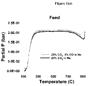
[0027] Figures 1(a) and 1(b) are graphs of temperature against
regeneration feed partial
pressure and regeneration product partial pressure, respectively, during
heating of a coked
Mo/ZSM-5 catalyst in (a) a CO2/helium atmosphere and (b) a CO2/CO/helium
atmosphere
according to the process of Example 1.
[0028] Figure 2 is a graph of benzene yield against cycle number in the
methane
dehydrocyclization process of Example 2.
[0029] Figures 3 (a) to (d) and Figure 4 are graphs of normalized
benzene yield (with
respect to benzene yield at cycle 11) against cycle number in the methane
dehydrocyclization
process of Example 3.
DETAILED DESCRIPTION OF THE EMBODIMENTS
[0030] The terms "coke" and "carbonaceous material" are used herein
interchangeably to
mean the low hydrogen content (typically with a H/C molar ratio of less than
0.8, such as less
than 0.5), carbon-containing materials which are produced as the by-products
of catalytic
-5 -
CA 02813372 2013-03-28
WO 2012/047401 PCT/US2011/049269
reactions and which are essentially non-volatile solids at reaction
conditions. These may
include crystalline graphite, graphitic sheets, graphitic fragments, amorphous
carbon, or other
carbon containing structures which are essentially non-volatile solids at
reaction conditions.
[0031] The term "coked metal-containing catalyst" means a catalyst
composition which
comprises a catalytically active metal and which contains coke as a result of
use of the
catalyst composition in a catalytic reaction such that the activity of the
catalyst composition
for continued use in the reaction is impaired.
[0032] The terms "regenerating" and "regeneration" are used herein to
refer to a process
by which carbonaceous material on a coked metal-containing catalyst is removed
and/or
rendered less detrimental to the use of the catalyst composition in the
desired catalytic
reaction.
[0033] Described herein is a process for regenerating a coked metal-
containing catalyst,
in which the coked catalyst is contacted with an atmosphere containing carbon
dioxide and
carbon monoxide at a temperature of at least 400 C. Although the present
process has utility
with any metal-containing catalyst whose activity has been impaired as a
result of use in any
catalytic reaction, the process is particularly intended for regenerating a
metal-containing
catalyst used in the dehydrocyclization of methane to higher hydrocarbons
including aromatic
hydrocarbons. The invention will therefore now be more particularly described
with
reference to a methane dehydrocyclization reaction.
Feedstock
[0034] Any methane-containing feedstock can be used in the present
methane
dehydrocyclization reaction but in general the present process is intended for
use with a
natural gas feedstock. Other suitable methane-containing feedstocks include
those obtained
from sources such as coal beds, landfills, agricultural or municipal waste
fermentation, and/or
refinery gas streams.
[0035] Methane-containing feedstocks, such as natural gas, typically
contain carbon
dioxide and ethane in addition to methane. Ethane and other aliphatic
hydrocarbons that may
be present in the feed can of course be converted to desired aromatics
products in the
dehydrocyclization step. In addition, as will be discussed below, carbon
dioxide can also be
converted to useful aromatics products either directly in the
dehydrocyclization step or
indirectly through conversion to methane and/or ethane in a subsequent
hydrogen rejection
step.
- 6 -
CA 02813372 2013-03-28
WO 2012/047401 PCT/US2011/049269
[0036] Nitrogen and/or sulfur impurities are also typically present in
methane-containing
streams and may be removed, or reduced to low levels, prior to use of the
streams in the
process of the invention. In an embodiment, the feed to the dehydrocyclization
step contains
less than 100 ppm, for example less than 10 ppm, such as less than 1 ppm each
of nitrogen
and sulfur compounds.
[0037] In addition to methane, the feed to the dehydrocyclization step
may contain at
least one of hydrogen, water, oxygen, carbon monoxide and carbon dioxide in
order to assist
in coke mitigation. These additives can be introduced as separate co-feeds or
can be present
in the methane stream, such as, for example, where the methane stream is
derived from
natural gas containing carbon dioxide. Other sources of carbon dioxide may
include flue
gases, LNG plants, hydrogen plants, ammonia plants, glycol plants and phthalic
anhydride
plants.
[0038] In one embodiment, the feed to the dehydrocyclization step
contains carbon
dioxide and comprises about 90 to about 99.9 mol%, such as about 97 to about
99 mol%
methane and about 0.1 to about 10 mol%, such as about 1 to about 3 mol% CO2.
In another
embodiment, the feed to the dehydrocyclization step contains carbon monoxide
and
comprises about 80 to about 99.9 mol%, such as about 94 to about 99 mol%
methane and
about 0.1 to about 20 mol%, such as about 1 to about 6 mol% CO. In a further
embodiment,
the feed to the dehydrocyclization step contains steam and comprises about 90
to about 99.9
mol%, such as about 97 to about 99 mol% methane and about 0.1 to about 10
mol%, such as
about 1 to about 5 mol% steam. In yet a further embodiment, the feed to the
dehydrocyclization step contains hydrogen and comprises about 80 to about 99.9
mol%, such
as about 95 to about 99 mol% methane and about 0.1 to about 20 mol%, such as
about 1 to
about 5 mol% hydrogen.
[0039] The feed to the dehydrocyclization step can also contain higher
hydrocarbons than
methane, including aromatic hydrocarbons. Such higher hydrocarbons can be
recycled from
a subsequent hydrogen rejection step, added as separate co-feeds or can be
present in the
methane stream, such as, for example, when ethane is present in a natural gas
feed. Higher
hydrocarbons recycled from a subsequent hydrogen rejection step typically
include one-ring
aromatics and/or paraffins and olefins having predominately 6 or less, such as
5 or less, for
example 4 or less, typically 3 or less carbon atoms. In general, the feed to
the
dehydrocyclization step contains less than 5 wt%, such as less than 3 wt%, of
C3+
hydrocarbons.
- 7 -
CA 02813372 2013-03-28
WO 2012/047401 PCT/US2011/049269
Dehydrocyclization Reaction and Catalyst
[0040] In the dehydrocyclization reaction of the present process, the
methane containing
feedstock is contacted with a particulate metal-containing dehydrocyclization
catalyst under
conditions, normally non-oxidizing conditions and typically reducing
conditions, effective to
convert the methane to higher hydrocarbons, including benzene and naphthalene.
The
principal net reactions involved are as follows:
2CH4 <--). C2H4 + 2H2 (Reaction 1)
6CH4 <--). C6H6 + 9H2 (Reaction 2)
10CH4 <--). C10H8 + 16H2 (Reaction 3)
[0041] Carbon monoxide and/or dioxide that may be present in the feed
improve catalyst
activity and stability by facilitating reactions such as:
CO2 + coke ¨> 2 C 0 (Reaction 4)
but negatively impact equilibrium by allowing competing net reactions, such
as:
CO2 + CH4 <--). CO + 2H2 (Reaction 5).
[0042] Any dehydrocyclization catalyst effective to convert methane to
aromatics can be
used in the present process, although generally the catalyst will include a
metal component,
particularly a transition metal or compound thereof, on an inorganic support.
Conveniently,
the metal component is present in an amount between about 0.1% and about 20%,
such as
between about 1% and about 10%, by weight of the total catalyst. Generally,
the metal will
be present in the catalyst in elemental form or as a carbide species.
[0043] Suitable metal components for the catalyst include calcium,
magnesium, barium,
yttrium, lanthanum, scandium, cerium, titanium, zirconium, hafnium, vanadium,
niobium,
tantalum, chromium, molybdenum, tungsten, manganese, rhenium, iron, ruthenium,
cobalt,
rhodium, iridium, nickel, palladium, platinum, copper, silver, gold, zinc,
aluminum, gallium,
silicon, germanium, indium, tin, lead, bismuth and transuranium metals. Such
metal
components may be present in elemental form or as metal compounds, such as
oxides,
carbides, nitrides and/or phosphides, and may be employed alone or in
combination.
[0044] The inorganic support may be either amorphous or crystalline and
in particular
may be an oxide, carbide or nitride of boron, aluminum, silicon, phosphorous,
titanium,
scandium, chromium, vanadium, magnesium, manganese, iron, zinc, gallium,
germanium,
yttrium, zirconium, niobium, molybdenum, indium, tin, barium, lanthanum,
hafnium, cerium,
tantalum, tungsten, or other transuranium elements. In addition, the support
may be a porous
material, such as a microporous crystalline material or a mesoporous material.
As used
- 8 -
CA 02813372 2013-03-28
WO 2012/047401 PCT/US2011/049269
herein the term "microporous" refers to pores having a diameter of less than 2
nanometers,
whereas the term "mesoporous" refers to pores having a diameter of from 2 to
50 nanometers.
[0045] Suitable microporous crystalline materials include silicates,
aluminosilicates,
titanosilicates, aluminophosphates, metallophosphates, silicoaluminophosphates
or their
mixtures. Such microporous crystalline materials include materials having the
framework
types MFI (e.g., ZSM-5 and silicalite), MEL (e.g., ZSM-11), MTW (e.g., ZSM-
12), TON
(e.g., ZSM-22), MTT (e.g., ZSM-23), FER (e.g., ZSM-35), MFS (e.g., ZSM-57),
MWW
(e.g., MCM-22, PSH-3, SSZ-25, ERB-1, ITQ-1, ITQ-2, MCM-36, MCM-49 and MCM-56),
IWR (e.g., ITQ-24), KFI (e.g., ZK-5), BEA (e.g., zeolite beta), ITH (e.g., ITQ-
13), MOR
(e.g., mordenite), FAU (e.g., zeolites X, Y, ultrastabilized Y and
dealuminized Y), LTL (e.g.,
zeolite L), IWW (e.g., ITQ-22), VFI (e.g., VPI-5), AEL (e.g., SAPO-11), AFI
(e.g., ALPO-5)
and AFO (SAPO-41), as well as materials such as MCM-68, EMM-1, EMM-2, ITQ-23,
ITQ-
24, ITQ-25, ITQ-26, ETS-2, ETS-10, SAPO-17, SAPO-34 and SAPO-35. Suitable
mesoporous materials include MCM-41, MCM-48, MCM-50, FSM-16 and SBA-15.
[0046] Examples of preferred catalysts include molybdenum, tungsten, zinc,
rhenium and
compounds and combinations thereof on ZSM-5, silica or alumina.
[0047] The metal component can be dispersed on the inorganic support by
any means
well known in the art such as co-precipitation, incipient wetness,
evaporation, impregnation,
spray-drying, sol-gel, ion-exchange, chemical vapor deposition, diffusion and
physical
mixing. In addition, the inorganic support can be modified by known methods,
such as, for
example, steaming, acid washing, caustic washing and/or treatment with silicon-
containing
compounds, phosphorus-containing compounds, and/or elements or compounds of
Groups 1,
2, 3 and 13 of the Periodic Table of Elements. Such modifications can be used
to alter the
surface activity of the support and hinder or enhance access to any internal
pore structure of
the support.
[0048] In some embodiments, a non-catalytic particulate material may be
supplied to the
dehydrocyclization reaction in addition to the catalytic particulate material.
The non-catalytic
particulate material may be used as a material to transport energy (heat) into
the system
and/or to fill space as required providing the required hydrodynamic
environment. The non-
catalytic particulate material may form particulates without a binder or may
be bound with an
inorganic binder such as clay, silica, alumina, zirconia, or other metal oxide
used to help
maintain the physical integrity of the particles. Preferably the particles are
of a substantially
- 9 -
CA 02813372 2013-03-28
WO 2012/047401 PCT/US2011/049269
spherical shape. Examples of suitable non-catalytic particulate material are
low surface area
silica, alumina, ceramics, and silicon carbide.
[0049] The dehydrocyclization step is conducted by contacting the
methane-containing
feedstock with the particulate dehydrocyclization catalyst in one or more
fixed bed, moving
bed or fluidized bed reaction zones. Generally, the feedstock is contacted in
the or each
reaction zone with a moving bed of dehydrocyclization catalyst, wherein the
feedstock flows
countercurrent to the direction of movement of the dehydrocyclization
catalyst. In one
embodiment, the or each reaction zone comprises a settling bed reactor, by
which is meant a
vertically disposed reactor in which particulate catalyst enters at or near
the top of the reactor
and flows under gravity to form a catalyst bed, while the feed enters the
reactor at or near the
base of the reactor and flows upwardly through the catalyst bed.
[0050] The movement of the dehydrocyclization catalyst in the reaction
zone is
substantially free of fluidization in the settling bed embodiment. The term
"substantially free
of fluidization" as used herein means that the average gas flowing velocity in
the reactor is
lower than the minimum fluidizing velocity. The term "substantially free of
fluidization" as
used herein also means that the average gas flowing velocity in the reactor is
less than 99%,
such as less than 95%, typically less than 90%, even less than 80% of the
minimum
fluidization velocity. Where the or each reaction zone is operated as a
settling bed, the
particulate catalytic material and/or any particulate non-catalytic material
has an average
particle size from about 0.1 mm to about 100 mm, such as from about 1 mm to
about 5 mm,
and for example from about 2 mm to about 4 mm. In some embodiments, at least
90 wt% of
the particulate catalytic material and/or at least 90 wt% of the particulate
non-catalytic
material has a particle size from about 0.1 mm to about 100 mm, such as from
about 1 mm to
about 5 mm, for example from about 2 mm to about 4 mm.
[0051] In an alternative embodiment, the dehydrocyclization reaction is
conducted in a
plurality of series-connected fluidized bed reactors in which particulate
catalyst is cascaded in
one direction from one reactor to the next adjacent reactor in the series,
while the feed is
passed through and between the reactors in the opposite direction. Wherein
each reaction
zone is operated as a fluidizing bed, the catalytic particulate material
and/or any non-catalytic
particulate material has an average particle size from about 0.01 mm to about
10 mm, such as
from about 0.05 mm to about 1 mm, and for example from about 0.1 mm to about
0.6 mm. In
some embodiments, at least 90 wt% of the catalytic particulate material and/or
at least 90
wt% of the non-catalytic particulate material have particle size from about
0.01 mm to about
- 10 -
CA 02813372 2013-03-28
WO 2012/047401 PCT/US2011/049269
mm, such as from about 0.05 to about 1 mm, and for example from about 0.1 to
about 0.6
mm.
[0052]
Typically, the mass ratio of the flowrate of the catalytic particulate
material plus
any non-catalytic particulate material over the flowrate of the hydrocarbon
feedstock in the or
5 each dehydrocyclization reaction zone is from about 1:1 to about 100:1,
such as from about
1:1 to about 40:1, for example from about 5:1 to 20:1.
[0053]
The dehydrocyclization reaction is endothermic and hence the temperature in
each
dehydrocyclization reaction zone will tend to decrease from a maximum
temperature to a
minimum temperature as the reaction proceeds.
Suitable conditions for the
10 dehydrocyclization step include a maximum temperature of about 700 C to
about 1200 C,
such as about 800 C to about 950 C and a minimum temperature of about 400 C to
about
800 C, such as about 500 C to about 700 C. However, as will be discussed
below, heat is
supplied to the dehydrocyclization reaction to reduce the temperature drop
during the reaction
and hence in some configurations it is possible to reduce the difference
between the
maximum and minimum temperatures to essentially zero. Alternatively, by
supplying heated
catalyst to the dehydrocyclization reaction, it is possible to produce an
inverse temperature
profile; that is with the process gas outlet reaction temperature being
greater than the process
gas inlet reaction temperature.
[0054]
In one embodiment, the countercurrent flow of the feedstock and the
particulate
dehydrocyclization catalyst is arranged to produce an inverse temperature
profile across
dehydrocyclization reaction system, such that, despite the endothermic nature
of the
dehydrocyclization reaction, the difference between the reaction temperature
of the gaseous
effluent at the outlet from the dehydrocyclization reaction system and the
reaction
temperature of the methane-containing feed at the inlet to the
dehydrocyclization reaction
system is at least +10 C, such as at least +50 C, for example at least +100 C,
and even at
least +150 C.
[0055]
In any event, since the dehydrocyclization reaction is endothermic, the
catalytic
particulate material enters the dehydrocyclization reaction system at a first,
high temperature,
typically about 800 C to about 1200 C, such as about 900 C to about 1100 C,
and exits the
reaction system at a second lower temperature, typically about 500 C to about
800 C, such as
about 600 C to about 700 C. The total temperature difference of the catalytic
particulate
material across the reaction zones is at least 100 C.
- 11 -
CA 02813372 2013-03-28
WO 2012/047401 PCT/US2011/049269
[0056] Other conditions used in the dehydrocyclization reaction
generally include a
pressure of about 1 kPaa to about 1000 kPaa, such as about 10 to about 500
kPaa, for
example about 50 kPaa to about 200 kPaa and a weight hourly space velocity of
about 0.01 to
about 1000 hr', such as about 0.1 to about 500 hr', for example about 1 to
about 20 hr'.
Conveniently, the dehydrocyclization step is conducted in the absence of 02,
preferably less
than 100 ppm 02, more preferably less than 10 ppm 02, still more preferably
less than 1 ppm
02.
[0057] The major components of the effluent from the dehydrocyclization
step are
hydrogen, benzene, naphthalene, carbon monoxide, ethylene, and unreacted
methane.
Typically, the effluent contains at least 5 wt%, such as at least 10 wt%, for
example at least
wt%, conveniently at least 30 wt%, more aromatic rings than the feed.
[0058] The benzene and naphthalene are separated from the
dehydrocyclization effluent,
for example, by solvent extraction followed by fractionation, and can be
recovered as a
product stream. However, as will be discussed below, at least part of these
aromatic
15 components can be submitted to an alkylation step, before or after
product recovery, to
produce higher value materials, such as xylenes. Moreover, as will be
discussed below, the
present process utilizes the hydrogen generated as a by-product of the
dehydrocyclization
reaction and in particular converts at least part of the hydrogen to higher
value products.
Catalyst Re2eneration
20 [0059] The dehydrocyclization reaction tends to deposit coke on
the catalyst and hence,
to maintain the activity of the dehydrocyclization catalyst, at least part of
the catalyst must be
continuously or intermittently regenerated. This is typically achieved by
withdrawing a
portion of the catalyst from the or each reaction zone, either on an
intermittent, or a
continuous basis, and transferring the withdrawn catalyst to a separate
regeneration zone. In
the regeneration zone, the coked dehydrocyclization catalyst is contacted with
a gaseous
mixture of carbon monoxide and carbon dioxide under conditions effective to
remove at least
a portion of the carbonaceous material on the catalyst.
[0060] Generally, the ratio of the partial pressure of carbon monoxide
to the partial
pressure of carbon dioxide in the regeneration zone is in a ratio, based on
partial pressures, of
at least 2.3:1, more preferably in the range of 2.3:1 to 100:1, and still more
preferably from
about 10:1 to 100:1., In addition, the partial pressure of carbon dioxide in
the regeneration
zone is generally less than or equal 40 psia (276 kPaa), such as between about
0.1 and about
psia (0.7 to 276 kPaa). More particularly, the partial pressure of carbon
dioxide in the
- 12 -
CA 02813372 2013-03-28
WO 2012/047401 PCT/US2011/049269
regeneration zone is less than or equal 5 psia (34 kPaa), such as between
about 0.1 and about
3 psia (0.7 to 21 kPaa). Generally, the regeneration gas is substantially free
of molecular
oxygen (preferably less than 100 ppm 02, more preferably less than 10 ppm 02,
still more
preferably less than 1 ppm 02) and does not contain significant quantities of
methane or other
hydrocarbons; typically with the hydrocarbon content being less than 20 mol%,
such as less
than 10 mol%, for example less than 2 mol%.
[0061] Conveniently, the regeneration conditions comprise a temperature
of at least
400 C, such as from about 400 C to about 1200 C, such as from about 600 C to
about
800 C. In some cases, the coked dehydrocyclization catalyst removed from the
or each
reaction zone will be at a lower temperature than the optimum for regeneration
and hence the
removed catalyst is initially heated to a desired regeneration temperature by
direct and/or
indirect contact with combustion gases produced by combustion of a
supplemental fuel. The
heating is conducted in a heating zone which may be in the same vessel as the
regeneration
zone or which may be in a separate vessel from the regeneration zone.
[0062] By "supplemental source of fuel" is meant that the source fuel is
physically
separate from the catalyst and hence is not, for example, coke generated on
the catalyst as a
by-product of the dehydrocyclization reaction. Typically, the supplemental
source of fuel
comprises a hydrocarbon, such as methane, and in particular a suitable fuel
source is the
natural gas used as the feedstock to the process. Conveniently, an oxygen-lean
atmosphere is
maintained in the heating zone so that burning the hydrocarbon fuel to heat
the coked catalyst
produces synthesis gas, which can then be used to generate additional
hydrocarbon product
and/or fuel. In addition, in the case of direct heat transfer to the coked
catalyst, the use of an
oxygen-lean atmosphere inhibits oxidation of metal carbides present in the
catalyst and
minimizes the average steam partial pressure thereby reducing catalyst
hydrothermal aging.
[0063] Alternatively, a suitable supplemental fuel source is hydrogen and,
in particular,
part of the hydrogen generated as a by-product of the dehydrocyclization
reaction.
[0064] Where the dehydrocyclization catalyst is heated directly, the
coked catalyst
withdrawn from the reaction zone is conveniently contacted directly with the
burning source
of fuel in the heating zone. Alternatively, the source of fuel is burned in a
separate
combustion zone and the combustion gases generated in the combustion zone are
fed to the
heating zone to heat the catalyst. Alternatively, the dehydrocyclization
catalyst can be heated
by indirect heat exchange such as, for example, by using the combustion gases
to heat an
- 13 -
CA 02813372 2013-03-28
WO 2012/047401 PCT/US2011/049269
inert medium (gas, liquid, or solid) or a heat transfer surface and then
contacting the coked
catalyst with the heated inert medium or heat transfer surface.
[0065] In one practical embodiment, the heating zone is elongated and
the coked catalyst
is passed through the heating zone from an inlet at or adjacent one end of the
heating zone to
an outlet at or adjacent the other end of the heating zone, with heat being
applied to first
catalyst portion at a plurality of locations spaced along the length of the
heating zone. In this
way, the heat input to the catalyst can be distributed along the length of the
heating zone
thereby minimizing catalyst surface temperatures and internal gradients.
[0066] Where the coked catalyst is heated by direct contact with the
burning source of
fuel in the heating zone, gradual heating of the catalyst can be achieved by
supplying
substantially all of the supplemental fuel to the inlet end of the heating
zone and then
supplying the oxygen-containing gas incrementally to said heating zone at said
plurality of
spaced locations along the length of heating zone. Alternatively,
substantially all of the
oxygen-containing gas required to burn said supplemental fuel can be supplied
to the inlet
end of the heating zone and the supplemental fuel supplied incrementally to
the heating zone
at said plurality of spaced locations.
[0067] Where the coked catalyst portion is heated by direct contact with
hot combustion
gases generated in a separate combustion zone, gradual heating of the catalyst
can be
achieved by supplying the hot combustion gases to said plurality of spaced
locations along
the length of heating zone.
[0068] In one embodiment, the heating zone is a riser and the coked
catalyst is passed
upwardly through the riser during the reheating step. In practice, the heating
zone may
include a plurality of risers connected in parallel. Alternatively, said
heating zone can
include a moving bed of the coked catalyst.
[0069] Generally, regeneration is conducted by contacting the coked
catalyst with the
carbon monoxide/carbon dioxide mixture at the desired regeneration temperature
for a time
of less than 120 minutes, such as for between about 0.1 and about 60 minutes.
More
particularly, the coked catalyst is contacted with the carbon monoxide/carbon
dioxide mixture
at the desired regeneration temperature for a time of less than 15 minutes,
such as for
between about 0.1 and about 10 minutes. Although the mechanism of the
regeneration is not
fully understood it is believed that the carbon dioxide present in the
regeneration mixture
removes coke (CH) according to the following general reaction:
CH x + CO2 <-* wC0 + yH2 + zH20 (Reaction 6)
- 14 -
CA 02813372 2013-03-28
WO 2012/047401 PCT/US2011/049269
In addition, the presence of carbon monoxide at sufficient partial pressure to
maintain carbon
activity in the regeneration zone allows the catalytically active metal to be
maintained in a
reduced state or more preferably a carburized state, for example, in the case
of a
molybdenum-containing catalyst, in the MoCx form.
[0070] In one embodiment, regeneration is conducted by a combination of the
carbon
monoxide/carbon dioxide regeneration described above and by contacting the
coked catalyst
with an atmosphere containing hydrogen at a temperature of at least 400 C,
preferably at
about 600 C to about 850 C. This combined regeneration process can be
conducted
simultaneously, that is by contacting the coked catalyst with an atmosphere
containing CO,
CO2 and H2, or consecutively, that is by contacting the coked catalyst with an
atmosphere
containing CO and CO2 prior to and/or after contacting the coked catalyst with
an atmosphere
containing H2 in the same or different regeneration zones. The combined CO/CO2
and H2
regeneration achieves the advantages of hydrogen regeneration (efficient
removal of freshly
deposited coke while preserving metal dispersion) without build-up of
graphitic coke that can
occur with hydrogen regeneration alone.
[0071] Where the combined regeneration process is conducted in
consecutive steps, a
number of different alternative approaches can be adopted, for example:
(a) H2 regeneration can be used as the primary mode of maintaining catalyst
activity with an occasional CO/CO2 regeneration being used to remove heavy,
difficult to
remove (graphitic) coke. The frequency of CO/CO2 regeneration might vary
between from
every other regeneration to 1 in 10 or even 1 in 100 H2 regenerations.
(b) Each CO/CO2 regeneration can be followed with a H2 regeneration before
returning the catalyst from regeneration mode to on-oil operation.
(c) H2 regeneration can be used as the primary mode of maintaining catalyst
activity with an occasional CO/CO2 regeneration as in (a) above and with each
CO/CO2
regeneration being followed with a H2 regeneration before returning the
catalyst from
regeneration mode to on-oil operation.
[0072] With a combined CO/CO2 and H2 regeneration process, the ratio of
the partial
pressure of carbon monoxide to the partial pressure of carbon dioxide in the
CO/CO2
regeneration gas is preferably at least 2.3:1, more preferably in the range of
2.3:1 to 100:1,
and still more preferably from about 10:1 to 100:1.,and the partial pressure
of carbon dioxide
is preferably less than 20 psia (138 kPaa), such as between about 0.1 and
about 15 psia (7 to
103 kPaa). Typically, contacting with the CO/CO2 regeneration gas is for a
time of less than
- 15 -
CA 02813372 2013-03-28
WO 2012/047401 PCT/US2011/049269
20 minutes, such as for between about 0.1 and about 15 minutes, whereas
contacting with the
H2 regeneration gas is typically for a time greater than 4 minutes, such as
for between about
20 and about 60 minutes.
[0073] The or each regeneration zone may be a reactor operated as a
fluidized bed, an
ebulating bed, a settling bed, a riser reactor or a combination thereof. In
practice, each
regeneration zone may include a plurality of reactors, such as a plurality of
riser reactors
connected in parallel or a plurality of reactors connected in series such as a
riser reactor
followed by a settling bed. After regeneration the catalyst is returned to
reaction zone.
[0074] In an alternative embodiment, and particularly where the
dehydrocyclization
reaction is conducted in a fixed bed reactor, the regeneration can be
conducted without
removal of the catalyst from the reaction zone, by temporarily discontinuing
the supply of
methane-containing feedstock to the reaction zone, heating the reaction zone
to the desired
regeneration temperature by direct and/or indirect contact with combustion
gases produced
by combustion of a supplemental fuel, regenerating the particulate catalytic
material with a
CO/CO2-containing gas alone or in combination with a H2-containing gas, and
then re-
establishing the supply of methane-containing feedstock to the reaction zone.
It is to be
appreciated that heating the reaction zone to the regeneration temperature can
be effected
before the supply of methane-containing feedstock is discontinued.
Catalyst Reheating
[0075] Since the dehydrocyclization reaction is endothermic, it is
necessary to supply
heat to the reaction. In the present process, this is conveniently achieved by
withdrawing part
of the catalyst from the reaction zone, either on an intermittent or a
continuous basis,
supplying heat to the catalyst and then returning the heated catalyst back to
the reaction zone.
Since the hydrogen regeneration step described above also involves heating the
catalyst and
then recycling the heated regenerated catalyst back to the reaction zone, one
possible route
for supplying heat to the dehydrocyclization reaction is by means of the
regeneration process.
[0076] Alternatively, some or all of the heat required to maintain the
dehydrocyclization
reaction can be supplied by a separate catalyst reheating step. In this
embodiment, part of the
catalyst withdrawn for the reaction zone is transferred to a separate heating
zone, where again
the catalyst is heated by direct or indirect contact with hot combustion gases
generated by
burning a supplemental source of fuel. The heated catalyst is then returned to
the reaction
zone with or without undergoing hydrogen regeneration.
- 16 -
CA 02813372 2013-03-28
WO 2012/047401 PCT/US2011/049269
Catalyst Recarburizing
[0077] It will be appreciated that heating the dehydrocyclization
catalyst for the purposes
of regeneration and/or for heat transfer back the dehydrocyclization reaction
may subject the
catalyst to high temperature oxidizing conditions, especially where catalyst
heating involves
direct contact with hot combustion gases. As a result, metals, such as
rhenium, tungsten or
molybdenum, present in the dehydrocyclization catalyst may be converted during
the heating
step from their catalytically active elemental or carbide form to an oxide
species. Thus,
before being returned to the reaction zone, the regenerated and/or reheated
catalyst may be
transferred to a catalyst treatment zone separate from the regeneration zone,
the heating zone
and the reaction zone, where the catalyst is contacted with a carburizing gas
containing at
least one hydrocarbon selected from methane, ethane, propane, butane,
isobutene, hexane,
benzene and naphthalene. In some cases, the carburizing gas may also contain
at least one of
CO2, CO, H25 H20 and inert diluents. Alternatively, the carburizing gas may be
a mixture of
hydrogen and at least one of CO and CO2. Moreover, it may be desirable to
contact the
catalyst sequentially with a plurality of different carburizing gases, each
comprising a
hydrocarbon selected from methane, ethane, propane, butane, isobutene, hexane,
benzene and
naphthalene or a mixture of hydrogen and at least one of CO and CO2.
[0078] To avoid damage to the catalyst, the carburization process is
controlled so that the
maximum temperature in the catalyst treatment zone is less than the maximum
temperature in
the dehydrocyclization reaction zone, although typically the maximum
carburization
temperature is higher than the maximum temperature reached in the regeneration
zone.
Generally the maximum temperature in the catalyst treatment zone is from about
400 C to
about 1100 C, such as from about 500 C to about 900 C, with the minimum
temperature
being between 300 C and 500 C. Typically, the catalyst treatment zone is
operated at
pressures between 10 and 100 psia (69 and 690 kPa), such as between 15 and 60
psia (103
and 414 kPa). Generally, the average residence time of catalyst particles in
the catalyst
treatment zone will be between 0.1 and 100 minutes, for example between 1 and
20 minutes.
Under these conditions, the carburizing gas reacts with metal oxide species on
the catalyst to
return the metal to its catalytically active elemental or carbidic form. In
addition, the
carburizing gas can react with active surface sites on the catalyst support to
decrease their
tendency to generate coke in the dehydroaromatization reaction zone.
[0079] To maintain the temperature required for carburization of the
regenerated catalyst,
heat can be supplied to the catalyst and/or the carburizing gas prior to or
during the
- 17 -
CA 02813372 2013-03-28
WO 2012/047401 PCT/US2011/049269
carburization step. For example heat can be supplied to the catalyst by
indirect heating, by
contacting with hot flue gas from the reaction zone or the heating zone, by
contacting with
the hot gaseous effluent from the carburization process, or by mixing with
heated catalyst
from the heating zone. Heat is conveniently supplied to the carburization gas
by means of an
external furnace or heat exchanger or by with heated catalyst from the heating
zone.
[0080] The catalyst treatment zone may be operated as a fluidized bed
reactor, ebulating
bed reactor, settling bed reactor, riser reactor or circulating riser reactor.
In one embodiment,
the catalyst treatment zone comprises a settling bed reactor. Alternatively,
the catalyst
treatment zone comprises a single fluidized bed reactor with internal baffles
to prevent back-
mixing or a plurality of fluidized bed reactors in series with the regenerated
catalyst being
cascaded between adjacent reactors. In any event, contact in the catalyst
treatment zone is
facilitated by arranging that the regenerated catalyst and the carburizing gas
flow in opposite
directions in said catalyst treatment zone. Employing such a countercurrent
flow, a
temperature profile may be developed in the catalyst treatment zone such that
carburization
of the regenerated catalyst initially occurs at a low temperature but the
carburization
temperature increases as the catalyst flows through the bed.
[0081] In some cases, it may be desirable that the heated unregenerated
catalyst is
initially contacted with a H2-rich stream to partially or fully reduce the
metal component of
the catalyst prior to the carburization step. It may also be desirable to
subject the carburized
catalyst to post treatment with H2 and/or CO2 to strip off any excess carbon
that may have
been deposited on the catalyst by the carburization step.
[0082] In practice, as the dehydrocyclization reaction proceeds, fresh
dehydrocyclization
catalyst will be added to the process either to make up for catalyst lost by
mechanical attrition
or deactivation and, although there are multiple means of addition of fresh
catalyst, to avoid
damage to the catalyst, it is generally desirable to add fresh catalyst to a
region of the process
that is operating at a temperature below the maximum temperature in each
dehydrocyclization reaction zone. In one embodiment, fresh dehydrocyclization
catalyst is
added to the process by introduction into the catalyst treatment zone, whereby
the fresh
catalyst is contacted with the carburizing gas prior to transfer to the
reaction zone for contact
with the methane-containing feed. In another, embodiment the catalyst may be
added to the
lower temperature regions of a reactor system with an inverse temperature
profile.
- 18 -
CA 02813372 2013-03-28
WO 2012/047401 PCT/US2011/049269
Hydrogen Management
[0083] Since hydrogen is a major component of the dehydrocyclization
effluent, after
recovery of the aromatic products, the effluent is subjected to a hydrogen
rejection step to
reduce the hydrogen content of the effluent before the unreacted methane is
recycled to the
dehydrocyclization step and to maximize feed utilization. Typically the
hydrogen rejection
step comprises reacting at least part of the hydrogen in the
dehydrocyclization effluent with
an oxygen-containing species, such as CO and/or CO2, to produce water and a
second
effluent stream having a reduced hydrogen content compared with the first
(dehydrocyclization) effluent stream. Suitable hydrogen rejection processes
are described
below and in our copending PCT Application Serial No. PCT/U52005/044042
(Attorney
Docket No. 2004B154), filed on December 2, 2005.
[0084] Conveniently, the hydrogen rejection step includes (i)
methanation and/or
ethanation, (ii) a Fischer-Tropsch process, (iii) synthesis of C1 to C3
alcohols, particularly
methanol, and other oxygenates, (iv) synthesis of light olefins, paraffins
and/or aromatics by
way of a methanol or dimethyl ether intermediate and/or (v) selective hydrogen
combustion.
These steps may be employed sequentially to gain the greatest benefit; for
example Fischer-
Tropsch may first be employed to yield a C2+ enriched stream followed by
methanation to
achieve high conversion of the H2.
[0085] Typically, as described below, the hydrogen rejection step will
generate
hydrocarbons, in which case, after separation of the co-produced water, at
least a portion of
the hydrocarbons is conveniently recycled to the dehydrocyclization step. For
example,
where the hydrocarbons produced in the hydrogen rejection step comprise
paraffins and
olefins, the portion recycled to the dehydrocyclization step conveniently
comprises, paraffins
or olefins with 6 or less carbon atoms, such as 5 or less carbon atoms, for
example 4 or less
carbon atoms or 3 or less carbon atoms. Where, the hydrocarbons produced in
the hydrogen
rejection step comprise aromatics, the portion recycled to the
dehydrocyclization step
conveniently comprises single ring aromatic species.
Methanation/Ethanation
[0086] In one embodiment the hydrogen rejection step comprises reaction
of at least part
of the hydrogen in the dehydrocyclization effluent with carbon dioxide to
produce methane
and/or ethane according to the following net reactions:
CO2 + 4H2 <---). CH4 + 2H20 (Reaction 7)
2CO2 + 7H2 <---). C2H6 + 4H20 (Reaction 8)
- 19 -
CA 02813372 2013-03-28
WO 2012/047401 PCT/US2011/049269
[0087]
The carbon dioxide employed is conveniently part of a natural gas stream and
typically the same natural gas stream used as the feed to the
dehydrocyclization step. Where
the carbon dioxide is part of a methane-containing stream, the CO2:CH4 of the
stream is
conveniently maintained between about 1:1 and about 0.1:1. Mixing of the
carbon dioxide-
containing stream and the dehydrocyclization effluent is conveniently achieved
by supplying
the gaseous feeds to the inlet of a jet ejector.
[0088]
The hydrogen rejection step to produce methane or ethane normally employs a
H2:CO2 molar ratio close to the stoichiometric proportions required for the
desired Reaction 7
or Reaction 8, although small variations can be made in the stoichiometric
ratio if it is desired
to produce a CO2-containing or H2-containing second effluent stream. The
hydrogen
rejection step to produce methane or ethane is conveniently effected in the
presence of a
bifunctional catalyst comprising a metal component, particularly a transition
metal or
compound thereof, on an inorganic support. Suitable metal components comprise
copper,
iron, vanadium, chromium, zinc, gallium, nickel, cobalt, molybdenum,
ruthenium, rhodium,
palladium, silver, rhenium, tungsten, iridium, platinum, gold, gallium and
combinations and
compounds thereof. The inorganic support may be an amorphous material, such as
silica,
alumina or silica-alumina, or like those listed for the dehydroaromatization
catalyst. In
addition, the inorganic support may be a crystalline material, such as a
microporous or
mesoporous crystalline material.
Suitable porous crystalline materials include the
aluminosilicates, aluminophosphates and silicoaluminophosphates listed above
for the
dehydrocyclization catalyst.
[0089]
The hydrogen rejection step to produce methane and/or ethane can be conducted
over a wide range of conditions including a temperature of about 100 C to
about 900 C, such
as about 150 C to about 500 C, for example about 200 C to about 400 C, a
pressure of about
200 kPa to about 20,000 kPa, such as about 500 to about 5000 kPa and a weight
hourly space
velocity of about 0.1 to about 10,000 hr-1, such as about 1 to about 1,000 hr-
1. CO2
conversion levels are typically between 20 and 100% and conveniently greater
than 90%,
such as greater than 99%. This exothermic reaction may be carried out in
multiple catalyst
beds with heat removal between beds. In addition, the lead bed(s) may be
operated at higher
temperatures to maximize kinetic rates and the tail beds(s) may be operated at
lower
temperatures to maximize thermodynamic conversion.
[0090]
The main products of the reaction are water and, depending on the H2:CO2
molar
ratio, methane, ethane and higher alkanes, together with some unsaturated C2
and higher
-20-
CA 02813372 2013-03-28
WO 2012/047401 PCT/US2011/049269
hydrocarbons. In addition, some partial hydrogenation of the carbon dioxide to
carbon
monoxide is preferred. After removal of the water, the methane, carbon
monoxide, any
unreacted carbon dioxide and higher hydrocarbons can be fed directly to the
dehydrocyclization step to generate additional aromatic products.
Fischer-Tropsch Process
[0091] In another embodiment the hydrogen rejection step comprises
reaction of at least
part of the hydrogen in the dehydrocyclization effluent with carbon monoxide
according to
the Fischer-Tropsch process to produce C2 to C5 paraffins and olefins.
[0092] The Fischer-Tropsch process is well known in the art, see for
example, U.S. Pat.
Nos. 5,348,982 and 5,545,674 incorporated herein by reference. The process
typically
involves the reaction of hydrogen and carbon monoxide in a molar ratio of
about 0.5:1 to
about 4:1, such as about 1.5:1 to about 2.5:1, at a temperature of about 175 C
to about 400 C,
such as about 180 C to about 240 C and a pressure of about 1 to about 100 bar
(100 to
10,000 kPa), such as about 10 to about 40 bar (1,000 to 4,000 kPa), in the
presence of a
Fischer-Tropsch catalyst, generally a supported or unsupported Group VIII, non-
noble metal,
e.g., Fe, Ni, Ru, Co, with or without a promoter, e.g. ruthenium, rhenium,
hafnium,
zirconium, titanium. Supports, when used, can be refractory metal oxides such
as Group
IVB, i.e., titania, zirconia, or silica, alumina, or silica-alumina. In one
embodiment, the
catalyst comprises a non-shifting catalyst, e.g., cobalt or ruthenium,
especially cobalt, with
rhenium or zirconium as a promoter, especially cobalt and rhenium supported on
silica or
titania, generally titania.
[0093] In another embodiment, the hydrocarbon synthesis catalyst
comprises a metal,
such as Cu, Cu/Zn or Cr/Zn, on the ZSM-5 and the process is operated to
generate significant
quantities of single-ring aromatic hydrocarbons. An example of such a process
is described
in Study of Physical Mixtures of Cr2O3 - ZnO and ZSM-5 Catalysts for the
Transformation of
Syngas into Liquid Hydrocarbons by Jose Erena; Ind. Eng. Chem Res. 1998, 37,
1211-1219,
incorporated herein by reference.
[0094] The Fischer-Tropsch liquids, i.e., C5+, are recovered and light
gases, e.g.,
unreacted hydrogen and CO, C1 to C3 or C4 and water are separated from the
heavier
hydrocarbons. The heavier hydrocarbons can then be recovered as products or
fed to the
dehydrocyclization step to generate additional aromatic products.
[0095] The carbon monoxide required for the Fischer-Tropsch reaction can
be provided
wholly or partly by the carbon monoxide present in or cofed with the methane-
containing
- 21 -
CA 02813372 2013-03-28
WO 2012/047401 PCT/US2011/049269
feed and generated as a by-product in the dehydrocyclization step. If
required, additional
carbon monoxide can be generated by feeding carbon dioxide contained, for
example, in
natural gas, to a shift catalyst whereby carbon monoxide is produced by the
reverse water gas
shift reaction:
CO2 + H2 <---> CO + H20 (Reaction 9)
and by the following reaction:
CH4 + H20 <---). CO + 3H2 (Reaction 10)
Alcohol Synthesis
[0096] In a further embodiment the hydrogen rejection step comprises
reaction of at least
part of the hydrogen in the dehydrocyclization effluent with carbon monoxide
to produce Ci
to C3 alcohols, and particularly methanol. The production of methanol and
other oxygenates
from synthesis gas is also well-known and is described in, for example, in
U.S. Patent Nos.
6,114,279; 6,054,497; 5,767,039; 5,045,520; 5,254,520; 5,610,202; 4,666,945;
4,455,394;
4,565,803; 5,385,949, the descriptions of which are incorporated herein by
reference.
Typically, the synthesis gas employed has a molar ratio of hydrogen (H2) to
carbon oxides
(CO + CO2) in the range of from about 0.5:1 to about 20:1, such as in the
range of from about
2:1 to about 10:1, with carbon dioxide optionally being present in an amount
of not greater
than 50% by weight, based on total weight of the syngas.
[0097] The catalyst used in the methanol synthesis process generally
includes an oxide of
at least one element selected from the group consisting of copper, silver,
zinc, boron,
magnesium, aluminum, vanadium, chromium, manganese, gallium, palladium, osmium
and
zirconium. Conveniently, the catalyst is a copper based catalyst, such as in
the form of
copper oxide, optionally in the presence of an oxide of at least one element
selected from
silver, zinc, boron, magnesium, aluminum, vanadium, chromium, manganese,
gallium,
palladium, osmium and zirconium. Conveniently, the catalyst contains copper
oxide and an
oxide of at least one element selected from zinc, magnesium, aluminum,
chromium, and
zirconium. In one embodiment, the methanol synthesis catalyst is selected from
the group
consisting of: copper oxides, zinc oxides and aluminum oxides. More
preferably, the catalyst
contains oxides of copper and zinc.
[0098] The methanol synthesis process can be conducted over a wide range of
temperatures and pressures. Suitable temperatures are in the range of from
about 150 C to
about 450 C, such as from about 175 C to about 350 C, for example from about
200 C to
about 300 C. Suitable pressures are in the range of from about 1,500 kPa to
about 12,500
- 22 -
CA 02813372 2013-03-28
WO 2012/047401 PCT/US2011/049269
kPa, such as from about 2,000 kPa to about 10,000 kPa, for example 2,500 kPa
to about
7,500 kPa. Gas hourly space velocities vary depending upon the type of process
that is used,
but generally the gas hourly space velocity of flow of gas through the
catalyst bed is in the
range of from about 50 hr-1 to about 50,000 hr-1, such as from about 250 hr-1
to about 25,000
hr-1, for example from about 500 hr-1 to about 10,000 hr-1. This exothermic
reaction may be
carried out in either fixed or fluidized beds, including multiple catalyst
beds with heat
removal between beds. In addition, the lead bed(s) may be operated at higher
temperatures to
maximize kinetic rates and the tail beds(s) may be operated at lower
temperatures to
maximize thermodynamic conversion.
[0099] The resultant methanol and/or other oxygenates can be sold as a
separate product,
can be used to alkylate the aromatics generated in the dehydrocyclization step
to higher value
products, such as xylenes, or can be used as a feedstock for the production of
lower olefins,
particularly ethylene and propylene. The conversion of methanol to olefins is
a well-known
process and is, for example, described in U.S. Patent No. 4,499,327,
incorporated herein by
reference.
Selective Hydrogen Combustion
[00100] In yet another embodiment, the hydrogen rejection step comprises
selective
hydrogen combustion, which is a process in which hydrogen in a mixed stream is
reacted
with oxygen to form water or steam without substantially reacting hydrocarbons
in the stream
with oxygen to form carbon monoxide, carbon dioxide, and/or oxygenated
hydrocarbons.
Generally, selective hydrogen combustion is carried out in the presence of an
oxygen-
containing solid material, such as a mixed metal oxide, that will release a
portion of the
bound oxygen to the hydrogen.
[00101] One suitable selective hydrogen combustion process is described in
U.S. Patent
No. 5,430,210, incorporated herein by reference, and comprises contacting at
reactive
conditions a first stream comprising hydrocarbon and hydrogen and a second
stream
comprising oxygen with separate surfaces of a membrane impervious to non-
oxygen
containing gases, wherein said membrane comprises a metal oxide selective for
hydrogen
combustion, and recovering selective hydrogen combustion product. The metal
oxide is
typically a mixed metal oxide of bismuth, indium, antimony, thallium and/or
zinc.
[00102] U.S. Patent No. 5,527,979, incorporated herein by reference, describes
a process
for the net catalytic oxidative dehydrogenation of alkanes to produce alkenes.
The process
involves simultaneous equilibrium dehydrogenation of alkanes to alkenes and
the selective
- 23 -
CA 02813372 2013-03-28
WO 2012/047401 PCT/US2011/049269
combustion of the hydrogen formed to drive the equilibrium dehydrogenation
reaction further
to the product alkenes. In particular, the alkane feed is dehydrogenated over
an equilibrium
dehydrogenation catalyst in a first reactor, and the effluent from the first
reactor, along with
oxygen, is then passed into a second reactor containing a metal oxide catalyst
which serves to
selectively catalyze the combustion of hydrogen. The equilibrium
dehydrogenation catalyst
may comprise platinum and the selective metal oxide combustion catalyst may
contain
bismuth, antimony, indium, zinc, thallium, lead and tellurium or a mixture
thereof.
[00103] U.S. Patent Application Publication No. 2004/0152586, published August
5, 2004
and incorporated herein by reference, describes a process for reducing the
hydrogen content
of the effluent from a cracking reactor. The process employs a catalyst system
comprising
(1) at least one solid acid cracking component and (2) at least one metal-
based selective
hydrogen combustion component consisting essentially of (a) a metal
combination selected
from the group consisting of: i) at least one metal from Group 3 and at least
one metal from
Groups 4-15 of the Periodic Table of the Elements; ii) at least one metal from
Groups 5-15 of
the Periodic Table of the Elements, and at least one metal from at least one
of Groups 1, 2,
and 4 of the Periodic Table of the Elements; iii) at least one metal from
Groups 1-2, at least
one metal from Group 3, and at least one metal from Groups 4-15 of the
Periodic Table of the
Elements; and iv) two or more metals from Groups 4-15 of the Periodic Table of
the
Elements; and (b) at least one of oxygen and sulfur, wherein the at least one
of oxygen and
sulfur is chemically bound both within and between the metals.
[00104] The selective hydrogen combustion reaction of the present invention is
generally
conducted at a temperature in the range of from about 300 C. to about 850 C
and a pressure
in the range of from about 1 atm to about 20 atm (100 to 2000 kPa).
Aromatic Product Recovery/Treatment
[00105] In addition to hydrogen, the other major products of the
dehydrocyclization step
are benzene and naphthalene. These products can be separated from the
dehydrocyclization
effluent, typically by solvent extraction followed by fractionation, and then
sold directly as
commodity chemicals. Alternatively, some or all of the benzene and/or
naphthalene can be
alkylated to produce, for example, toluene, xylenes and alkyl naphthalenes
and/or can be
subjected to hydrogenation to produce, for example, cyclohexane, cyclohexene,
dihydronaphthalene (benzylcyclohexene), tetrahydronaphthalene
(tetralin),
hexahydronaphthalene (dicyclohexene), octahydronaphthalene and/or
decahydronaphthalene
(decalin). Suitable alkylation and hydrogenation processes are described below
and in more
- 24 -
CA 02813372 2013-03-28
WO 2012/047401 PCT/US2011/049269
detail in our copending PCT Application Serial Nos. PCT/US2005/043523,
(Attorney Docket
No. 2004B156), filed on December 2, 2005 and PCT/US2005/044038, (Attorney
Docket No.
2004B155), filed on December 2, 2005.
Aromatics Alkylation
[00106] Alkylation of aromatic compounds such as benzene and naphthalene is
well
known in the art and typically involves reaction of an olefin, alcohol or
alkyl halide with the
aromatic species in the gas or liquid phase in the presence of an acid
catalyst. Suitable acid
catalysts include medium pore zeolites (i.e., those having a Constraint Index
of 2-12 as defined
in U.S. Patent No. 4,016,218), including materials having the framework types
MFI (e.g.,
ZSM-5 and silicalite), MEL (e.g., ZSM-11), MTW (e.g., ZSM-12), TON (e.g., ZSM-
22),
MTT (e.g., ZSM-23), MFS (e.g., ZSM-57) and FER (e.g., ZSM-35) and ZSM-48, as
well as
large pore zeolites (i.e, those having a Constraint Index of less than 2) such
as materials having
the framework types BEA (e.g., zeolite beta), FAU (e.g., ZSM-3, ZSM-20,
zeolites X, Y,
ultrastabilized Y and dealuminized Y), MOR (e.g., mordenite), MAZ (e.g., ZSM-
4), MEI
(e.g., ZSM-18) and MWW (e.g., MCM-22, PSH-3, SSZ-25, ERB-1, ITQ-1, ITQ-2, MCM-
36,
MCM-49 and MCM-56).
[00107] In one embodiment of the present process, benzene is recovered from
the
dehydrocyclization effluent and then alkylated with an olefin, such as
ethylene produced as a
by-product of a hydrogen rejection step employing ethanation/methanation.
Typical
conditions for carrying out the vapor phase alkylation of benzene with
ethylene include a
temperature of from about 650 to 900 F (343 to 482 C), a pressure of about
atmospheric to
about 3000 psig (100 to 20,800 kPa), a WHSV based on ethylene of from about
0.5 to about 2.0
hr-1 and a mole ratio of benzene to ethylene of from 1:1 to 30:1. Liquid phase
alkylation of
benzene with ethylene may be carried out at a temperature between 300 and 650
F (150 to
340 C), a pressure up to about 3000 psig (20,800 kPa), a WHSV based on
ethylene of from
about 0.1 to about 20 hr-1 and a mole ratio of benzene to ethylene of from 1:1
to 30:1.
[00108] Conveniently, the benzene ethylation is conducted under at least
partial liquid
phase conditions using a catalyst comprising at least one of zeolite beta,
zeolite Y, MCM-22,
PSH-3, SSZ-25, ERB-1, ITQ-1, ITQ-2, ITQ-13, ZSM-5 MCM-36, MCM-49 and MCM-56.
[00109] The benzene ethylation can be conducted at the site of the
dehydrocyclization/hydrogen rejection process or the benzene can be shipped to
another
location for conversion to ethylbenzene. The resultant ethylbenzene can then
be sold, used as
- 25 -
CA 02813372 2013-03-28
WO 2012/047401 PCT/US2011/049269
a precursor in, for example, the production of styrene or isomerized by
methods well known
in the art to mixed xylenes.
[00110] In another embodiment of the present process, the alkylating agent is
methanol or
dimethylether (DME) and is used to alkylate benzene and/or naphthalene
recovered from the
dehydrocyclization effluent to produce toluene, xylenes, methylnaphthalenes
and/or
dimethylnaphthalenes. Where the methanol or DME is used to alkylate benzene,
this is
conveniently effected in the presence of catalyst comprising a zeolite, such
as ZSM-5, zeolite
beta, ITQ-13, MCM-22, MCM-49, ZSM-11, ZSM-12, ZSM-22, ZSM-23, ZSM-35, and ZSM-
48, which has been modified by steaming so as to have a Diffusion Parameter
for 2,2
dimethylbutane of about 0.1-15 sec-1 when measured at a temperature of 120 C
and a 2,2
dimethylbutane pressure of 60 torr (8kPa). Such a process is selective to the
production of
para-xylene and is described in, for example, U.S. Patent No. 6,504,272,
incorporated herein
by reference. Where the methanol is used to alkylate naphthalene, this is
conveniently
effected in the presence of a catalyst comprising ZSM-5, MCM-22, PSH-3, SSZ-
25, ERB-1,
ITQ-1, ITQ-2, ITQ-13, MCM-36, MCM-49 or MCM-56. Such a process can be used to
selectively produce 2,6-dimethylnaphthalene and is described in, for example,
U.S. Patent
Nos. 4,795,847 and 5,001,295, incorporated herein by reference.
[00111] Where methanol or DME is used as an alkylating agent in the process of
the
invention, it can be provided as a separate feed to the process or can at
least partly be
generated in situ by adding a carbon dioxide-containing feed gas, such as a
natural gas
stream, to part or all of the effluent from the dehydrocyclization step. In
particular, the
dehydrocyclization effluent, prior to any separation of the aromatic
components, can be fed to
a reverse shift reactor and reacted with the carbon dioxide-containing feed
under conditions
to increase the carbon monoxide content of the effluent by reactions, such as
Reactions 5 and
8 above.
[00112] In addition, methane and CO2 and/or steam may be fed to a reverse
shift reactor to
generate syngas which can then be mixed with a portion of the
dehydrocyclization effluent to
adjust the H2/CO/CO2 ratios as required for the alkylation step.
[00113] Typically, the reverse shift reactor contains a catalyst comprising a
transition
metal on a support, such as Fe, Ni, Cr, Zn on alumina, silica or titania, and
is operated under
conditions including a temperature of about 500 C to about 1200 C, such as
about 600 C to
about 1000 C, for example about 700 C to about 950 C and a pressure of about 1
kPa to
about 10,000 kPa, such as about 2,000 kPa to about 10,000 kPa, for example
about 3000 kPa
-26-
CA 02813372 2013-03-28
WO 2012/047401 PCT/US2011/049269
to about 5,000 kPa. Gas hourly space velocities may vary depending upon the
type of
process used, but generally the gas hourly space velocity of flow of gas
through the catalyst
bed is in the range of about 50 hr-1 to about 50,000 hr-1, such as about 250
hr-1 to about
25,000 hr-1, more for example about 500 hr-1 to about 10,000 hr-1.
[00114] The effluent from the reverse shift reactor can then be fed to an
alkylation reactor
operating under conditions to cause reactions such as the following to occur:
CO + 2H2 <---). CH3OH (Reaction 11)
CH3OH + C6H6 ¨> toluene + H20 (Reaction 12)
2CH3OH + C6H6 ¨> xylenes + 2H20 (Reaction 13)
[00115] Suitable conditions for such an alkylation reactor would include a
temperature of
about 100 to about 700 C, a pressure of about 1 to about 300 atmospheres (100
to 30,000
kPa), and a WHSV for the aromatic hydrocarbon of about 0.01 to about 100 hr-1.
A suitable
catalyst would comprise a molecular sieve having a constraint index of 1 to
12, such as ZSM-
5, typically together with one or metals or metal oxides, such as copper,
chromium and/or
zinc oxide.
[00116] Conveniently, where the alkylation catalyst includes a molecular
sieve, the latter
is modified to change its diffusion characteristics such that the predominant
xylene isomer
produced by Reaction 11 is paraxylene. Suitable means of diffusion
modification include
steaming and ex-situ or in-situ deposition of silicon compounds, coke, metal
oxides, such as
MgO, and/or P on the surface or in the pore mouths of the molecular sieve.
Also preferred is
that an active metal be incorporated into the molecular sieve so as to
saturate more highly
reactive species, such as olefins, which may be generated as by-products and
which could
otherwise cause catalyst deactivation.
[00117] The effluent from the alkylation reactor could then be fed to a
separation section
in which the aromatic products would initially be separated from the hydrogen
and other low
molecular weight materials, conveniently by solvent extraction. The aromatics
products
could then be fractionated into a benzene fraction, a toluene fraction, a C8
fraction and a
heavy fraction containing naphthalene and alkylated naphthalenes. The C8
aromatic fraction
could then be fed to a crystallization or sorption process to separate the
valuable p-xylene
component and the remaining mixed xylenes either sold as product or fed to an
isomerization
loop to generate more p-xylene. The toluene fraction could either be removed
as saleable
product, recycled to the alkylation reactor or fed to a toluene
disproportionation unit, such as
a selective toluene disproportionation unit for the preparation of additional
p-xylene.
- 27 -
CA 02813372 2013-03-28
WO 2012/047401 PCT/US2011/049269
Aromatics Hydrogenation
[00118] In addition to or instead of the alkylation step, at least part of the
aromatic
components in the dehydrocyclization effluent can be hydrogenated to generate
useful
products such as cyclohexane, cyclohexene, dihydronaphthalene
(benzylcyclohexene),
tetrahydronaphthalene (tetralin), hexahydronaphthalene (dicyclohexene),
octahydronaphthalene and/or decahydronaphthalene (decalin). These products can
be
employed as fuels and chemical intermediates and, in the case of tetralin and
decalin, can be
used as the solvent for extracting the aromatic components from the
dehydrocyclization
effluent.
[00119] The hydrogenation is conveniently, but not necessarily, conducted
after separation
of the aromatic components from the dehydrocyclization effluent and
conveniently employs
part of the hydrogen generated by the dehydrocyclization reaction. Suitable
aromatic
hydrogenation processes are well known in the art and typically employ a
catalyst comprising
Ni, Pd, Pt, Ni/Mo or sulfided Ni/Mo supported on alumina or silica support.
Suitable
operating conditions for the hydrogenation process include a temperature of
about 300 to
about 1,000 F (150 to 540 C), such as about 500 to about 700 F (260 to 370 C),
a pressure
of about 50 to about 2,000 psig (445 to 13890 kPa), such as about 100 to about
500 psig (790
to 3550 kPa) and a WHSV of about 0.5 to about 50 hr-1, such as about 2 to
about 10 hr-1.
[00120] Partial hydrogenation to leave one or more olefinic carbon-carbon
bonds in the
product may also be desirable so as to produce materials suitable for
polymerization or other
downstream chemical conversion. Suitable partial hydrogenation processes are
well known
in the art and typically employ a catalyst comprising noble metals with
ruthenium being
preferred supported on metallic oxides, such as La203-ZnO. Homogeneous noble
metal
catalyst systems can also be used. Examples of partial hydrogenation processes
are disclosed
in US Patent Nos. 4,678,861; 4,734,536; 5,457,251; 5,656,761; 5,969,202; and
5,973,218, the
entire contents of which are incorporated herein by reference.
[00121] An alternative hydrogenation process involves low pressure
hydrocracking of the
naphthalene component to produce alkylbenzenes over a catalyst such as
sulfided Ni/W or
sulfided Ni supported on an amorphous aluminosilicate or a zeolite, such as
zeolite X, zeolite
Y or zeolite beta. Suitable operating conditions for low pressure
hydrocracking include a
temperature of about 300 to about 1,000 F (150 to 540 C), such as about 500 to
about 700 F
(260 to 370 C), a pressure of about 50 to about 2,000 psig (445 to 13890 kPa),
such as about
-28-
CA 02813372 2013-03-28
WO 2012/047401 PCT/US2011/049269
100 to about 500 psig (790 to 3550 kPa) and a WHSV of about 0.5 to about 50 hr-
1, such as
about 2 to about 10 hr'.
[00122] The invention will now be more particularly described with reference
to the
accompanying drawings and the following non-limiting Examples.
Example 1
[00123] Separate samples of a coked Mo/ZSM-5 catalyst (having a Si/Al2 ratio
of 25:1 and
a Mo loading of 7.5 wt% and a coke level of 12.4 wt%) were heated from 100 C
to about
925 C in (a) a helium atmosphere containing 20 mol% carbon dioxide and (b) a
helium
atmosphere containing 20 mol% carbon dioxide and 8 mol% carbon monoxide. The
composition of the feed in each test is shown in Figure 1(a) and the
composition of the
product in each test is shown in Figure 1(b) and Table 1.
Table 1
Compound Amount of compound generated at T>600 C (mmol/g catalyst)
20%CO2/He 20%CO2/8%CO/He
CO21 8.7 8.5
CO 17.9 16.9
H2 0.45 0.59
H20 0.48 0.41
1
CO2 consumed ¨ all other species generated.
[00124] It will be seen that the amount of CO detected in each test was equal
to about
twice the amount of CO2 consumed.
Example 2
[00125] A 300 mg Mo/ZSM-5 catalyst aliquot (having a Si/Al2 ratio of 25:1 and
a Mo
loading of 7.5 wt%) diluted with 750 mg quartz was subjected to the following
activation,
methane dehydrocyclization and regeneration cycles:
Activation (a) Heat catalyst in 75 sccm He at 5 C/minute to 500 C and hold
for 6
hours at a He pressure of 24 psia (165 kPaa);
(b) Cool to 125 C in He;
(c) Carburize Mo by heating catalyst with 75 sccm of 85 mol% H2/15
mol% CH4 mixture at 5 C/minute to 800 C and then holding for 0.5
hour at 24 psia (165 kPaa);
(d) Cool to 785 C in H2/CH4 mixture;
(e) Initiate dehydrocyclization reaction.
-29-
CA 02813372 2013-03-28
WO 2012/047401 PCT/US2011/049269
Dehydrocyclization (a) Supply hydrocarbon feed (75.2% CH4, 12.9% H2, 9.99% Ar,
1.73%
CO and 0.21% C2H4, all by mol%) at 49 sccm and 785 C for 4
minutes;
(b) Initiate H2 or COx regeneration cycle.
H2 Regeneration (a) After dehydrocyclization cycle, optionally purge with
75 sccm He
at 785 C for 5 minutes;
(b) Switch to 75 sccm H25 ramp at 5 C/minute to 875 C and hold for
24 minutes at a H2 pressure of 50 psia (345 kPaa);
(c) Optionally purge for 5 minutes with 75 sccm He while reactor cools
to 785 C;
(d) Initiate dehydrocyclization cycle.
COx Regeneration (a) After dehydrocyclization cycle, purge with 75 sccm
He for 15
minutes while reactor cools to 750 C;
(b) Switch to 75 sccm of 1.2% CO2, 2.8% CO (a CO to CO2 partial
pressure ratio of 2.3:1), 96% He (all mol %) at a total pressure of 40
psia (276 kPaa) and CO2 partial pressure of 0.5 psia (3.45 kPaa) for 1
minute;
(c) Purge for 10 minutes with 75 sccm He and ramp temperature at
5 C/minute in He to 785 C. Continue He purge until total purge time
is 15 minutes.
(d) Initiate dehydrocyclization cycle.
[00126] In the test, after activation, the catalyst was subjected to
alternating
dehydrocyclization and H2 regeneration cycles for 10 cycles until, after the
eleventh
dehydrocyclization cycle, the catalyst was subjected to a COx regeneration
cycle. This was
repeated for a total of 67 dehydrocyclization cycles. In each case,
performance was
significantly higher following the COx regeneration and remained stable for
the ensuing 10
H2 regenerations.
[00127] After 67 dehydrocyclization cycles, the protocol was changed to use 2
COx
regeneration cycles after each 10 H2 regenerations. The number of COx
regeneration cycles
after each 10 H2 regenerations was increased to two and performance was still
stable but
declined somewhat after the two COx regeneration cycles and five H2
regeneration cycles.
Subsequently, the number of COx regeneration cycles after each five H2
regenerations was
increased to four but resulted in further loss in catalyst performance.
- 30 -
CA 02813372 2013-03-28
WO 2012/047401 PCT/US2011/049269
[00128] The results are summarized in Figure 2 and Table 2.
Table 2
No. reaction Regen gas Regen time Coke after Comments
cycles (mins) regen (wt%)
87 He 1 9.35 750 C, 40
psia
154 H2 24 Est. 4.64 875 C, 50
psia
111 CO x 1 7.91 750 C, 40
psia
(Pc02=0.5 psia)
173 CO x 4 5.34 875 C, 24
psia
(Pc02=7 psia)
204 H2/C0x 24/1 3.38 750 C, 40
psia
(Expt. B in (Pc02=0.5 psia)
Figure 2)
Example 3
[00129] 300 mg Mo/ZSM-5 catalyst aliquots (having a Si/Al2 ratio of 25:1 and a
Mo
loading of 7.5 wt%) diluted with 750 mg quartz were subjected to alternating
methane
dehydrocyclization and CO x regeneration cycles as described in Table 3 below.
Table 3
Temp Time
for for Partial
CO x CO x pressure Partial
Expt regen regen P
- total PC0x CO2 pressure Ratio:
No ( C) (min) (psia)* (psia) (psia) CO (psia) CO to CO2
1 750 1 23 10 2.3 7.7 3.3
2 750 1 20 20 6.0 14.0 2.3
3 925 1 23 10 0.9 9.1 10.1
4 925 1 61 40 3.6 36.4 10.1
5 750 4 23 10 3.0 7.0 2.3
6 750 4 23 10 0.9 9.1 10.1
7 750 20 23 10 0.9 9.1 10.1
8 750 1 23 10 0.9 9.1 10.1
9 750 4 23 3 0.3 2.7 9.0
750 4 20 20 9.0 11.0 1.2
11 750 4 40 40 18.0 22.0 1.2
12 925 4 23 10 0.9 9.1 10.1
13 750 1 40 40 18.0 22.0 1.2
14 700 4 23 10 4.5 5.5 1.2
700 12 23 10 4.5 5.5 1.2
16 700 12 23 10 3.0 7.0 2.3
* Includes dilution with He gas when applicable.
- 31 -
CA 02813372 2013-03-28
WO 2012/047401 PCT/US2011/049269
[00130] The results summarized in Figure 3a-d demonstrate the following:
= cox regeneration at 925 C caused rapid deactivation and permanent damage
of the
catalyst of Example 3. Figure 3a shows dramatically higher recovery after H2
regeneration for Expt. 6 and Expt. 1 (750 C) as compared with Expt. 12 and
Expt. 3
(925 C)
= COx regeneration at 700 C, also in Figure 3a, (Expt. 15 and Expt. 16) did
not
efficiently remove coke from the catalyst of Example 3 and seemed to damage
the
catalyst in that catalyst activity could only be partially recovered by H2
regeneration.
= Using the catalyst and conditions tested, COx regeneration at 750 C
seemed to
produce the best results.
= The results in Figure 3b show that at high CO2 partial pressure (Expt. 11
at 18 psia
CO2, Expt. 10 at 9 psia CO2) performance declines rapidly and recovery after
H2
regeneration (after cycle 61) is less than at low CO2 partial pressure, such
as those
observed in Expt. 5 at 3 psia CO2, Expt. 6 at 0.9 psia CO2, Expt. 9 at 0.3
psia CO2.
= Figure 3c also shows that shorter regeneration time [Expt. 6 (1 min) as
compared with
Expt. 7 (20 min)] results in better performance recovery after H2 regeneration
after
Cycle 61 at low CO2 partial pressures (0.9 psia). This effect is even more
pronounced
at higher CO2 partial pressures [at 18 psia for Expt. 13 (1 min) as compared
with
Expt. 11 (4 min) and at 4.5 psi for Expt. 14 (4 min) and Expt. 15 (12 min)].
= With the catalyst of Example 3 and effecting COx regeneration at 750 C for 1
minute,
the recovery after H2 regeneration seemed to improve with lower CO2 partial
pressures as shown in Figure 3d [e.g., Expt. 8 (0.9 psia CO2-best) as compared
with
Expt. 1 (2.3 psia CO2-good) and Expt. 13 (18 psia CO2-poor)] and higher CO/CO2
ratios as shown in Figure 4.
[00131] While the present invention has been described and illustrated by
reference to
particular embodiments, those of ordinary skill in the art will appreciate
that the invention
lends itself to variations not necessarily illustrated herein. For this
reason, then, reference
should be made solely to the appended claims for purposes of determining the
true scope of
the present invention.
- 32 -