Language selection

Search

Patent 2813852 Summary

Third-party information liability

Some of the information on this Web page has been provided by external sources. The Government of Canada is not responsible for the accuracy, reliability or currency of the information supplied by external sources. Users wishing to rely upon this information should consult directly with the source of the information. Content provided by external sources is not subject to official languages, privacy and accessibility requirements.

Claims and Abstract availability

Any discrepancies in the text and image of the Claims and Abstract are due to differing posting times. Text of the Claims and Abstract are posted:

  • At the time the application is open to public inspection;
  • At the time of issue of the patent (grant).
(12) Patent: (11) CA 2813852
(54) English Title: A RADIAL BEARING FOR MOUNTING A SHAFT
(54) French Title: PALIER RADIAL POUR SUPPORT D'UN ARBRE
Status: Granted and Issued
Bibliographic Data
(51) International Patent Classification (IPC):
  • F16C 17/03 (2006.01)
  • F16C 17/02 (2006.01)
  • F16C 33/04 (2006.01)
  • F16C 33/08 (2006.01)
  • F16C 33/10 (2006.01)
(72) Inventors :
  • HOLSTEIN, BENJAMIN (Germany)
  • LOCHSCHMIDT, JOERG (Germany)
(73) Owners :
  • VOITH PATENT GMBH
(71) Applicants :
  • VOITH PATENT GMBH (Germany)
(74) Agent: GOWLING WLG (CANADA) LLP
(74) Associate agent:
(45) Issued: 2017-11-21
(86) PCT Filing Date: 2011-12-07
(87) Open to Public Inspection: 2012-07-19
Examination requested: 2016-11-25
Availability of licence: N/A
Dedicated to the Public: N/A
(25) Language of filing: English

Patent Cooperation Treaty (PCT): Yes
(86) PCT Filing Number: PCT/EP2011/006114
(87) International Publication Number: EP2011006114
(85) National Entry: 2013-04-05

(30) Application Priority Data:
Application No. Country/Territory Date
10 2010 054 106.0 (Germany) 2010-12-10

Abstracts

English Abstract


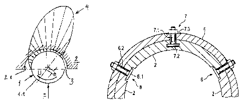
The invention relates to a radial bearing for mounting a shaft, comprising the
following features:
- several bearing shells which are curved according to the radius of the
shaft
and whose inner surface forms the plain bearing surfaces;
- a housing enclosing the bearing shells;
- at least one of the end regions of the respective bearing shell as seen
in the
circumferential direction is held in an interlocking manner on the housing in
such a way that expansion and/or displacement of the end region or the
entire bearing shell is possible;
- means for setting the curvature of the individual bearing shell.


French Abstract

L'invention concerne un palier radial pour soutenir un arbre, comprenant les caractéristiques suivantes: plusieurs coussinets (2) présentant une courbure correspondant au rayon de l'arbre (1), et dont les surfaces internes constituent les surfaces de glissement du palier (2.1); un corps (5) entourant les coussinets; au moins une des deux parties terminales des coussinets respectifs, vue dans la direction de la périphérie, est retenue par complémentarité de forme, d'une manière permettant une dilatation et/ou un déplacement de la partie terminale ou du coussinet entier; des moyens (7) pour régler la courbure des coussinets individuels.

Claims

Note: Claims are shown in the official language in which they were submitted.


7
What is claimed is:
1. A radial bearing for mounting a shaft, the radial bearing comprising:
a plurality of bearing shells curved according to a radius of the shaft,
wherein inner surfaces of the
plurality of bearing shells form plain bearing surfaces, wherein each of the
plurality of bearing shells
forms a single plain bearing surface;
a housing enclosing the plurality of bearing shells, wherein the housing
comprises an inner
jacket surface and an outer jacket surface;
each of the plurality of bearing shells is clamped to the housing at least at
two circumferential
ends of each of the plurality of bearing shells;
a bar embedded in the each of the plurality of bearing shells;
an adjusting pin guided through the housing, the adjusting pin having a
radially inner end on the bar
and an engagement element for displacing the adjusting pin and the bar at a
radially outer end of the
adjusting pin.
2. The radial bearing according to claim 1, wherein the plurality of
bearing shells comprise at least
one of plastic, and metal.
3. The radial bearing according to claim 2, further comprising:
a shell holder for touching points of each two mutually adjacent bearing
shells of the plurality of the
bearing shells;
wherein each of the shell holders comprises a holding strip extending over an
axial length of the
radial bearing and is inserted into recesses of the plurality of bearing
shells;
each of the holding strips is fixed to a holding pin, each of the holding pins
being guided
through a thickness of at least one of the plurality of bearing shells and
through the housing and fixed
to the outer jacket surface of the housing.
4. The radial bearing according to claim 3, wherein radially inner surfaces
of the holding strips lie
radially outside of inner jacket surfaces of the plurality of bearing shells.
5. The radial bearing according to claim 2, wherein the plurality of
bearing shells are brought to a
final shape for a bearing function only during mounting.

8
6. The radial bearing according to claim 5, further comprising:
a shell holder for touching points of each two mutually adjacent bearing
shells of the plurality of the
bearing shells;
wherein each of the shell holders comprises a holding strip extending over an
axial length of the
radial bearing and is inserted into recesses of the plurality of bearing
shells;
each of the holding strips is fixed to a holding pin, each of the holding pins
being guided
through a thickness of at least one of the plurality of bearing shells and
through the housing and fixed
to the outer jacket surface of the housing.
7. The radial bearing according to claim 6, wherein radially inner surfaces
of the holding strips lie
radially outside of inner jacket surfaces of the plurality of bearing shells.
8. The radial bearing according to claim 5, wherein the plurality of
bearing shells are mounted
using at least one spacer element and at least one of a clamping and a holding
element, a slackness and
the curvature of each of the plurality of bearing shells being set during
mounting via a position and a
selection of the spacer and at least one of the clamping and holding element.
9. The radial bearing according to claim 8, further comprising:
a shell holder for touching points of each two mutually adjacent bearing
shells of the plurality of the
bearing shells;
wherein each of the shell holders comprises a holding strip extending over an
axial length of the
radial bearing and is inserted into recesses of the plurality of bearing
shells;
each of the holding strips is fixed to a holding pin, each of the holding pins
being guided
through a thickness of at least one of the plurality of bearing shells and
through the housing and fixed
to the outer jacket surface of the housing.
10. The radial bearing according to claim 9, wherein radially inner
surfaces of the holding strips lie
radially outside of inner jacket surfaces of the plurality of bearing shells.
11. The radial bearing according to claim 1, further comprising:
a shell holder for touching points of each two mutually adjacent bearing
shells of the plurality of the
bearing shells;
wherein each of the shell holders comprises a holding strip extending over an
axial length of the
radial bearing and is inserted into recesses of the plurality of bearing
shells;
each of the holding strips is fixed to a holding pin, each of the holding pins
being guided

9
through a thickness of at least one of the plurality of bearing shells and
through the housing and fixed
to the outer jacket surface of the housing.
12. The radial bearing according to claim 11, wherein radially inner
surfaces of the holding strips
lie radially outside of inner jacket surfaces of the plurality of bearing
shells.

Description

Note: Descriptions are shown in the official language in which they were submitted.


CA 02813852 2017-01-18
=
1
A radial bearing for mounting a shaft
The invention relates to a bearing for mounting a shaft in the radial
direction.
Such bearings are known in a large number of varieties.
In the present case, a bearing with a housing is concerned which is lined with
bearing shells. There are bearing shells which represent closed bushings.
There
are also linings consisting of several shells, which respectively represent
segments
and which are joined into a more or less closed ring within the housing.
The invention is based on such segment bearing shells. The individual segments
are fixed to the inside surface of the housing, e.g. by gluing or screwing,
and
therefore in a non-positive way.
This leads to numerous disadvantages. One important disadvantage lies in the
type of fixing itself. As a result, gluing is often not durable. Screwed
joints can
also loosen over time. Moreover, the bearing clearance and the segment shell
curvature cannot be adjusted, so that optimal lubrication is not ensured.
The invention is based on the object of providing a radial bearing which
comprises
plain bearing areas formed by segment shells, in which the bearing clearance
and
the segment shell curvature are adjustable and which has a mechanically simple
configuration.
This object is achieved by the features of claim 1.
The interlocked fixing of the bearing shells in accordance with the invention
allows
a certain expansion and/or displacement of at least the end region of the
individual shells. This property plays a role in the adjustment of the
segments. The
curvature and the position of the shelves relative to the shaft can be
adjusted. For

CA 02813852 2017-01-18
2
this purpose, a packing plate or a comparable spacer element of selected
thickness can be inserted between the individual shells and the housing. This
preferably occurs between the two ends of the respective shell, as seen in the
circumferential direction, preferably in the middle region. Alternatively, a
shell
holder or a comparable clamping or holding element which fixes the shell in
relation to the housing can be guided from the outside through the housing and
also through the respective shell. The segment shell curvature and the bearing
clearance can be set with the shell holders or comparable clamping or holding
means in combination with respective spacer elements. A certain flexibility of
the
shell is of decisive importance in this respect. This flexibility allows that
the
segment shell curvature can be varied during mounting by clamping or holding
elements between the shell and the housing in combination with respective
spacer
elements between the shell and housing. As a result, the bearing shells will
be
brought to their respective shape relevant for the bearing function only
during
mounting. This procedure offers the possibility to reduce the precision
requirements in segment production and to subsequently adjust the bearings
after
a certain operating time in a simple way.
The invention is shown in closer detail in the drawings, which show the
following
in detail:
Fig. 1 shows a schematic illustration of an axial sectional view
through a
radial bearing with an adjusting device for varying the curvature of a
bearing shell.
Fig. 2 shows the hydrodynamic pressure buildup in a cylindrical plain
bearing;
Fig. 3 shows a shaft with a bearing in accordance with the invention
in an
axially perpendicular sectional view;

CA 02813852 2013-04-05
3
Fig. 5 shows a schematic illustration of an axial sectional view
through a
radial bearing with an adjusting device for varying the curvature of a
bearing shell.
Fig. 1 shows a revolving shaft 1. It is mounted by a plain bearing 2. A
bearing
clearance 3 is disposed between the two, which is formed by the outer surface
1.1
of the shaft and the bearing surface 2.1 of the bearing.
The bearing clearance 3 tapers during the rotation of the shaft 1 in the
circumferential direction U. A pressure field 4 is built up over the bearing
clearance. It leads to an eccentricity e of the shaft 1 relative to the
bearing 2.
The radial bearing in accordance with the invention and according to Figs. 2
and 3
comprises a number of bearing shells 2 with bearing surfaces 2.1. The bearing
shells can consist of any material, e.g. plastic or metal. Polyurethane or any
other
polymer is suitable as a bearing material in configurations that use synthetic
material.
The bearing shells 2 are made of a solid sleeve which was subdivided after
production into the segments that are shown here.
The bearing shells are enclosed by a housing 5 which consists of steel for
example.
Shell holders 6 are provided as clamping or holding elements for fixing the
bearing
shells 2 to the housing. They comprise a holding strip 6.1 which extends over
the
axial length of the bearing shells and which engages into recesses of the
mutually
adjacent bearing shells. The depth of the recess and thickness of the holding
strip

CA 02813852 2013-04-05
4
6.1 are dimensioned in such a way that the inside surface of the holding strip
6.1
is flush with the bearing surface 2.1.
Each shell holder 6 further comprises a plurality of holding pins 6.2. They
are
guided through the housing 5 and through the bearing shell 2 and fixed to
holding
strips 6.1. They protrude beyond the outer jacket surface of the housing 5.
They
comprise a thread with which a screw 6.3 is screwed together.
Generally, the shell holder 6 will consist of metal. The holding strip 6.1 can
consist
of a composite material, the radially inner region of which is made of the
same or
a similar material as the bearing shell 2.
As is shown in the sectional view according to Fig. 4, the fixing of the
bearing
shells 2 on the housing 5 is provided by means of interlocking. It allows a
certain
displacement or movement of the individual bearing shell 2.
The curvature of the individual bearing shell 2 is variable. For this purpose,
a
packing plate or a strip of another material (not shown) can be inserted as a
spacer element between the bearing shell 2 and the housing 5. The bearing
shell
2 is preferably mounted at virtually three points, as seen in an axially
perpendicularly sectional view: on the one hand, at both of its ends (as seen
in
the circumferential direction) by means of the shell holder 6, and on the
other
hand in a middle region by the packing plate.
Fig. 4 further shows that the holding strip 6.1 is offset relative to the
inner jacket
surface of the bearing shell 2. It therefore has a distance from the jacket
surface
of the shaft (not shown) in order to avoid contact with said shaft.
Instead, the device shown in Fig. 5 can also be considered.

CA 02813852 2013-04-05
Fig. 5 again shows a housing 5 with a completely shown shell 2, adjacent to
which
there are two further shells 2 on either side, which are only partly shown
here.
An adjusting device 7 is provided for setting the curvature of the shell 2. It
5 comprises a pin 7.1, at the radially inner end of which a bar 7.2 is
provided. The
bar 7.2 is embedded in the material of the shell 2. The pin 7.1 protrudes
beyond
the radially outer jacket surface of the housing 5. It carries a thread there,
onto
which a nut 7.3 is screwed. The radial position of the bar 7.2 can be varied
by
means of the nut 7.3. The curvature of the shell 2 can be adjusted in this
way.
The adjusting device fulfils both the function of the spacer element and also
the
function of the clamping or holding element.
The device for adjusting the curvature of the bearing shell is preferably
located in
the centre between the two circumferential ends of the respective bearing
shell.

CA 02813852 2013-04-05
6
List of reference numerals
1. Shaft
1.1 Jacket surface of the shaft
2 Bearing, bearing shell
2.1 Bearing surface
3 Bearing clearance
4 Pressure field
5 Housing
6 Shell holder
6.1 Holding strip
6.2 Holding pin
6.3 Screw
7 Adjusting device
7.1 Adjusting pin
7.2 Bar
7.3 Nut

Representative Drawing
A single figure which represents the drawing illustrating the invention.
Administrative Status

2024-08-01:As part of the Next Generation Patents (NGP) transition, the Canadian Patents Database (CPD) now contains a more detailed Event History, which replicates the Event Log of our new back-office solution.

Please note that "Inactive:" events refers to events no longer in use in our new back-office solution.

For a clearer understanding of the status of the application/patent presented on this page, the site Disclaimer , as well as the definitions for Patent , Event History , Maintenance Fee  and Payment History  should be consulted.

Event History

Description Date
Letter Sent 2023-12-07
Revocation of Agent Requirements Determined Compliant 2021-04-06
Appointment of Agent Requirements Determined Compliant 2021-04-06
Inactive: Associate patent agent removed 2021-04-06
Revocation of Agent Request 2021-03-19
Change of Address or Method of Correspondence Request Received 2021-03-19
Appointment of Agent Request 2021-03-19
Revocation of Agent Request 2021-02-10
Appointment of Agent Request 2021-02-10
Appointment of Agent Requirements Determined Compliant 2020-03-26
Revocation of Agent Requirements Determined Compliant 2020-03-26
Inactive: Associate patent agent added 2020-03-26
Revocation of Agent Request 2020-02-19
Appointment of Agent Request 2020-02-19
Common Representative Appointed 2019-10-30
Appointment of Agent Request 2018-04-03
Revocation of Agent Request 2018-04-03
Inactive: Office letter 2018-03-23
Revocation of Agent Request 2018-02-15
Appointment of Agent Request 2018-02-15
Inactive: Adhoc Request Documented 2018-01-30
Change of Address or Method of Correspondence Request Received 2018-01-16
Appointment of Agent Request 2017-12-19
Revocation of Agent Request 2017-12-19
Grant by Issuance 2017-11-21
Inactive: Cover page published 2017-11-20
Inactive: Final fee received 2017-10-03
Pre-grant 2017-10-03
Letter Sent 2017-09-13
Notice of Allowance is Issued 2017-09-13
Inactive: Q2 passed 2017-09-08
Inactive: Approved for allowance (AFA) 2017-09-08
Amendment Received - Voluntary Amendment 2017-01-18
Letter Sent 2016-12-02
All Requirements for Examination Determined Compliant 2016-11-25
Request for Examination Requirements Determined Compliant 2016-11-25
Request for Examination Received 2016-11-25
Revocation of Agent Requirements Determined Compliant 2015-08-12
Appointment of Agent Requirements Determined Compliant 2015-08-12
Amendment Received - Voluntary Amendment 2013-06-19
Inactive: Cover page published 2013-06-19
Inactive: First IPC assigned 2013-05-08
Inactive: Notice - National entry - No RFE 2013-05-08
Inactive: IPC assigned 2013-05-08
Application Received - PCT 2013-05-08
National Entry Requirements Determined Compliant 2013-04-05
Application Published (Open to Public Inspection) 2012-07-19

Abandonment History

There is no abandonment history.

Maintenance Fee

The last payment was received on 2016-11-23

Note : If the full payment has not been received on or before the date indicated, a further fee may be required which may be one of the following

  • the reinstatement fee;
  • the late payment fee; or
  • additional fee to reverse deemed expiry.

Patent fees are adjusted on the 1st of January every year. The amounts above are the current amounts if received by December 31 of the current year.
Please refer to the CIPO Patent Fees web page to see all current fee amounts.

Owners on Record

Note: Records showing the ownership history in alphabetical order.

Current Owners on Record
VOITH PATENT GMBH
Past Owners on Record
BENJAMIN HOLSTEIN
JOERG LOCHSCHMIDT
Past Owners that do not appear in the "Owners on Record" listing will appear in other documentation within the application.
Documents

To view selected files, please enter reCAPTCHA code :


To view images, click a link in the Document Description column. To download the documents, select one or more checkboxes in the first column and then click the "Download Selected in PDF format (Zip Archive)" or the "Download Selected as Single PDF" button.

List of published and non-published patent-specific documents on the CPD .

If you have any difficulty accessing content, you can call the Client Service Centre at 1-866-997-1936 or send them an e-mail at CIPO Client Service Centre.


Document
Description 
Date
(yyyy-mm-dd) 
Number of pages   Size of Image (KB) 
Claims 2013-04-04 2 53
Drawings 2013-04-04 3 35
Representative drawing 2013-05-08 1 7
Abstract 2013-04-04 1 15
Claims 2017-01-17 3 109
Description 2017-01-17 6 161
Description 2013-04-04 6 162
Representative drawing 2017-10-24 1 11
Notice of National Entry 2013-05-07 1 207
Reminder of maintenance fee due 2013-08-07 1 112
Reminder - Request for Examination 2016-08-08 1 117
Acknowledgement of Request for Examination 2016-12-01 1 174
Commissioner's Notice - Application Found Allowable 2017-09-12 1 162
Commissioner's Notice - Maintenance Fee for a Patent Not Paid 2024-01-17 1 541
PCT 2013-04-04 20 559
PCT 2013-06-18 7 229
Request for examination 2016-11-24 2 46
Amendment / response to report 2017-01-17 7 224
Final fee 2017-10-02 2 46
Courtesy - Office Letter 2018-03-22 1 24