Note: Descriptions are shown in the official language in which they were submitted.
CA 02814524 2013-04-11
WO 2012/054918 PCT/US2011/057475
COMMUNICATIONS WIRING NOISE
LEVEL MONITOR AND ALARM INDICATOR
CROSS REFERENCE TO RELATED APPLICATION
[0001] This application claims priority from U.S. Provisional Patent
Application
No. 61/405,846, filed October 22, 2010, which is incorporated herein by
reference.
BACKGROUND OF THE INVENTION
[0002] Field of the Invention
[0003] The present invention relates to test and measurement of one or more
pairs of
conductors used to deliver telephony, internet, and video services over
digital subscriber lines
(DSL).
[0004] Description of Related Art
[0005] Impairments in pairs of conductors, e.g., Tip-Ring pairs, utilized
to deliver
telephony, internet and video services over digital subscriber lines (DSL)
within or close to a
residence or other structure can render broadband service unreliable for
internet access and/or
for internet based services such as IPTV or VoIP. It has been observed that
much of the
inside wiring problems reduce down to abnormally high levels of differential
noise compared
to the signal levels received at an ATU-R modem (the customer's DSL modem
employed in
the residence or structure) that were sent by an ATU-C modem (the DSL service
provider's
DSL modem deployed outside the residence or structure), such as a central
office, and
operating under the control of the DSL service provider).
[0006] A centralized line test system, deployed upstream of the ATU-R
modem, sees
very little, if any, of the high frequency noise environment local to a
customer's residence or
structure due to line loss and high levels of high-frequency cross-talk
present upstream of the
customer's residence or structure.
[0007] Heretofore, prior solutions recorded a snapshot of the noise
environment and
signal-to-noise ratio (SNR) per DSL tone available at the ATU-R modem.
However, these
solutions rely on measurements made at showtime, defined as the successful
completion of a
DSL link between the customer's modem (ATU-R) and a DSL service provider's
modem
(ATU-C). Real-time measurements, however, are not available via these
solutions and any
DSL modem based measurement solutions are not available at all if
synchronization between
the customer's DSL modem (ATU-R) and the DSL service supplier's modem (ATU-C)
is
lost.
1
SUBSTITUTE SHEET (RULE 26)
CA 02814524 2013-04-11
WO 2012/054918 PCT/US2011/057475
SUMMARY OF THE INVENTION
[0008] The present invention is a device that is deployed in-line,
immediately before (just
upstream) of a customer's DSL modem (ATU-R). The device measures noise levels
in a pair
of conductors, a.k.a., a twisted-pair cable, that is utilized to deliver DSL
services to the
customer's residence or structure and determines whether the noise levels are
below or above
expected noise thresholds caused by crosstalk and naturally occurring sources
of noise. The
device can also determine whether the customer's modem (ATU-R) and the service
provider's modem (ATU-C) are present and able to initiate a handshake to begin
communication. The device can also recognize working or degraded service
regardless of the
synchronization state of the ATU-R and ATU-C modems. In addition, the device
can also
identify when an un-filtered telephone, facsimile machine, modem, or set top
box would
adversely affect DSL service.
[0009] The invention is intended primarily for in-home or residence
(structure) use, to aid
in the diagnosis and repair of the inside pair of wires utilized to deliver
DSL services. Also
or alternatively, the unit can be deployed at a network demarcation point,
such as, without
limitation, a so-called network interface device, to determine whether there
might be a
network fault as opposed to a wiring fault inside the
home/residence/structure.
[0010] Specifically, the invention is an in-line radio frequency (RF)
shielded
module which tests differential noise levels on wiring (a pair of wires)
connected to the
module and measures signal + noise at handshake time (when the ATU-R and ATU-C
DSL
moderns are establishing DSL connectivity), calculates maximum attainable bit-
rate, and
confirms whether the bandwidth available to the user is commensurate with the
loss of signal
from the central office/exchange. Missing or broken splitters (or micro-
filters) can also be
identified by monitoring the line for changes in noise background that are
coincident with a
change in the line feeding voltage.
[0011] More specifically, the invention is a method of testing the capacity
of a network
comprised of one or more (Tip-Ring) pairs of wires (6, 8, 8-1), an ATU-C modem
(10), and
an ATU-R modem (16) to support DSL services. The method comprises: (a)
providing a test
device (30) configured to be coupled to a pair of wires (8-1) in-line between
the ATU-C
modem (10) and the ATU-R modem (16). The test device (30) comprises: a
controller (66); a
DC sampling circuit (54) operative under the control of the controller (66);
an AC sampling
circuit (78) operative under the control of the controller (66); a first
connector (38) for
coupling the pair of wires (8-1) to a first end of a pair of internal
conductors (200, 202) of the
test device (30); a second connector (36) for coupling the ATU-R modem (16) to
a second
2
CA 02814524 2013-04-11
WO 2012/054918 PCT/US2011/057475
end of the pair of internal conductors (200, 202); and means for connecting
(57, 76) operative
under the control of the controller (66) for selectively connecting the AC
sampling circuit
(78) to the first end of the pair of internal conductors (200, 202), to the
second end of the pair
of internal conductors (200, 202), or to both the first and second ends of the
pair of internal
conductors (200, 202);
[0012] The method further comprises: (b) the DC sampling circuit (54)
samples for a DC
line feed or DC potential difference on the pair of internal conductors (200,
202) when the
means for connecting (57, 76) is connecting the AC sampling circuit (78) to
both the first and
second ends of the pair of internal conductors (200, 202); (c) the AC sampling
circuit (78)
samples for AC noise on the first end of the pair of internal conductors (200,
202) when the
means for connecting (57, 76) is connecting the AC sampling circuit (78) to
the first end of
the pair of internal conductors (200, 202) while isolating the second end of
the pair of internal
conductors (200, 202) from the AC sampling circuit (78); (d) the AC sampling
circuit (78)
also samples for DSL signals on the second end of the pair of internal
conductors (200, 202)
when the means for connecting (57, 76) is connecting the AC sampling circuit
(78) to the
second end of the pair of internal conductors (200, 202) while isolating the
first end of the
pair of internal conductors (200, 202) from the AC sampling circuit (78); (e)
the AC sampling
circuit (78) also samples for DSL signals on the pair of internal conductors
(200, 202) when
the means for connecting (57, 76) is connecting the AC sampling circuit (78)
to both the first
and second ends of the pair of internal conductors (200, 202); and (f) based
on the foregoing
samplings, the controller (66) determines the capacity of the network to
support DSL
services, wherein during the samplings the test device (30) is coupled to the
pair of wires (8-
1) in-line between the ATU-C modem (10) and the ATU-R modem (16).
[0013] The means for connecting can include: a first relay (57) operative
under the
control of the controller (66) for selectively connecting and disconnecting
the AC sampling
circuit (78) to and from the first end of the pair of internal conductors
(200, 202); and a
second relay (76) operative under the control of the controller (66) for
selectively connecting
and disconnecting the AC sampling circuit (78) to and from the second end of
the pair of
internal conductors (200, 202).
[0014] The controller (66) can operate under the control of non-transitory
computer
software code.
[0015] The test device (30) can include an indicator (46 and/or 48)
operative under the
control of the controller (66). The controller (66) can causing the indicator
to output an
indication of the controller (66) determined capacity of the network to
support DSL services.
3
CA 02814524 2013-04-11
WO 2012/054918 PCT/US2011/057475
[0016] The indicator can include at least one lamp (46) for outputting
light as the
indication of the determined capacity of the network to support DSL services,
the at least one
lamp outputting first and second colors in response to the controller (66)
determining that the
network is respectively capable and not capable of supporting DSL services.
Also or
alternatively, the indicator can include a display (48) for outputting a first
visual pattern in
response to the controller (66) determining that the network is capable of
supporting DSL
services and for outputting a second visual pattern in response to the
controller (66)
detennining that the network is not capable of supporting DSL services.
[0017] The test device (30) can further include a network analyzer (60)
operative under
the control of the controller (66). The method can further include: (g) the
network analyzer
(60) outputting one or more AC signals to the pair of wires (8-1) via the pair
of internal
conductors (200, 202); (h) the AC sampling circuit (78) sampling the pair of
wires (8-1) for
the response to the one or more AC signals output by the network analyzer (60)
in step (g);
and (i) the controller responsive to the sampled response of the AC sampling
circuit (78) in
step (h) for determining the presence or absence of at least one DSL service
affecting
condition.
[0018] The at least one DSL service affecting condition can include at
least one of the
following: an impedance that is either higher or lower than a predetermined
impedance
threshold; and the presence of a bridged tap.
[0019] In step (e), the AC sampling circuit (78) can sample at least one of
the following:
DSL tones transmitted during restoration of communication between the ATU-C
modem (10)
and the ATU-R modem (16); and DSL tones transmitted between the ATU-C modem
(10)
and the ATU-R modem (16) after restoration of communication between the ATU-C
modem
(10) and the ATU-R modem (16).
[0020] The test device (30) can be coupled in-line with the pair of wires
(8-1) between
the ATU-R modem (16) which is deployed inside of a structure and a network
interface
device (4) which is mounted to the structure, wherein the network interface
device (4) is
coupled in-line with the pair of wires (8-1) between the ATU-R modern (16) and
the ATU-C
modem (10).
[0021] The second connector (36) of the test device (30) can be coupled
directly to the
ATU-R modern (16).
[0022] The invention is also a method of testing the capacity of a network
comprised of
one or more pairs of wires (6, 8, 8-1), an ATU-C modern (10), and an ATU-R
modem (16) to
support DSL services. The method comprises: (a) with the ATU-R modem (16)
operatively
4
CA 02814524 2013-04-11
WO 2012/054918 PCT/US2011/057475
coupled to an ATU-C modem (10) via a pair of wires (8-1), sampling for a DC
line feed or
DC potential difference on the pair of wires (8-1); (b) with the ATU-R modem
(16)
electrically isolated from the ATU-C modem (10) which is operatively coupled
to the pair of
wires (8-1), sampling for AC noise present on the pair of wires (8-1); (c)
with the ATU-C
modem (10) electrically isolated from the ATU-R modem (16), sampling for DSL
signals
output by the ATU-R modem (16); (d) with the ATU-R modem (16) operatively
coupled to
the ATU-C modem (10) via the pair of wires (8-1), sampling for DSL signals on
the pair of
wires (8-1); and (e) based on the sampling in steps (a), (b), (c), and (d),
determining the
capacity of the network to support DSL services.
[0023] Step (d) can include sampling for DSL signals during and following
restoration of
handshake between the ATU-C modem (10) and the ATU-R modem (16).
[0024] Step (e) can include illuminating a lamp, generating a visual
pattern, or both in
response to the determined capacity of the network to support DSL services.
[0025] The capacity of the network to support DSL services determined in
step (e) can
include at least one of the following: a number useable DSL tones; a number
unusable DSL
tones; insertion loss; signal-to-noise ratio per DSL tone; bit-loading per DSL
tone; crest
factor per DSL tone; maximum data rate per DSL tone; and maximum total data
rate for all
useable DSL tones.
[0026] Lastly, the invention is a test device (30) for testing the capacity
of a network
comprised of one or more pairs of wires (6, 8, 8-1), an ATU-C modem (10), and
an ATU-R
modem (16) to support DSL services. The test device (30) comprises: a
controller (66); a DC
sampling circuit (54) operative under the control of the controller (66); an
AC sampling
circuit (78) operative under the control of the controller (66); a first
connector (38) for
coupling a pair of wires (8-1) to a first end of a pair of internal conductors
(200, 202) of the
test device (30); a second connector (36) for coupling the ATU-R modem (16) to
a second
end of the pair of internal conductors (200, 202); and means for connecting
(57, 76) operative
under the control of the controller (66) for selectively connecting the AC
sampling circuit
(78) to the first end of the pair of internal conductors (200, 202), to the
second end of the pair
of internal conductors (200, 202), or to both the first and second ends of the
pair of internal
conductors (200, 202).
[0027] The means for connecting can include: a first relay (57) operative
under the
control of the controller (66) for selectively connecting and disconnecting
the AC sampling
circuit (78) to and from the first end of the pair of internal conductors
(200, 202); and a
second relay (76) operative under the control of the controller (66) for
selectively connecting
CA 02814524 2013-04-11
WO 2012/054918 PCT/US2011/057475
and disconnecting the AC sampling circuit (78) to and from the second end of
the pair of
internal conductors (200, 202).
[0028] The test device can further include a network analyzer (60)
operative under the
control of the controller (66), wherein, under the control of the controller
(66) the means for
connecting (57, 76) is operative for selectively connecting and disconnecting
the network
analyzer (60) to and from at least one of the following: the first end of the
pair of internal
conductors (200, 202), the second end of the pair of internal conductors (200,
202), or the
both the first and second ends of the pair of internal conductors (200, 202)
simultaneously.
[0029] The one or more of the pairs (6, 8, 8-1) of wires can be twisted
pairs.
BRIEF DESCRIPTION OF THE DRAWINGS
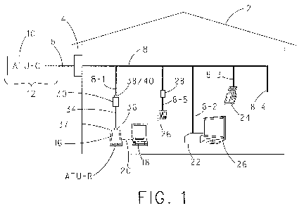
[0030] Fig. 1 is an exemplary residence, structure or home including
wiring/cabling for
distribution of telephony and DSL services;
[0031] Fig. 2 is a perspective view of the device shown in Fig. 1 connected
in-line in an
unfiltered extension of the internal cable of the residence, structure or home
shown in Fig. 1
that services an ATU-R modem;
[0032] Fig. 3 is a schematic diagram of the internal electrical components
of the device
shown in Fig. 2; and
[0033] Fig. 4 is an exemplary flow diagram of a method of operation of the
device shown
in Figs. 2 and 3.
DETAILED DESCRIPTION OF THE INVENTION
[0034] The present invention will be described with reference to the
accompanying
figures where like reference numbers correspond to like elements.
[0035] With reference to Fig. 1, an exemplary residence, structure or home
2 (hereinafter
"residence 2") can include a network interface device 4 which facilitates
connection of an
external pair of wires (Tip-Ring pair) or twisted-pair cable 6 to an internal
pair of wires (Tip-
Ring pair) or twisted-pair cable 8. Typically, the wires of cable 6 and 8 are
copper wires.
However, this is not to be construed as limiting the invention.
[0036] Opposite network interface device 4, cable 6 is operatively
connected to a service
provider's DSL modem (ATU-C) 10. As is known in the art, a path 12 between
modem 10
and cable 6 can include, for example, without limitation, one or more of the
following: a
central office (CO), a toll office (TO), a remote terminal (RT), and/or other
network
demarcation points. [0037] In one non-limiting embodiment, the CO typically
houses the
main telephony switching equipment for the residence 2 and can serve as the
location for the
DSL service provider's modem (ATU-C). In one non-limiting embodiment, the TO
and the
6
CA 02814524 2013-04-11
WO 2012/054918
PCT/US2011/057475
RT are connected by one or more pairs of wires (or twisted-pair cables), and
the CO is
connected to the TO via a fiber optic link. This discussion, however, of
elements that can
comprise path 12 and where the DSL service provider's DSL modem (ATU-C) 10 is
deployed is not to be construed as limiting the invention since it is
envisioned that path 12
can be any suitable and/or desirable combination of twisted-pair cable and
fiber optics, and
that the service provider's DSL modem 10 can be deployed at any suitable
and/or desirable
network point that facilitates the provision of DSL broadband service to
residence 2 via cable
6.
[0038] In the embodiment of residence 2 shown in Fig. 1, the customer's DSL
modem
(ATU-R) 16 is connected to an unfiltered extension 8-1 of cable 8. A computer
18 can be
coupled to modem 16 via an Ethernet connection 20 in a manner known in the
art. The
illustration in Fig. 1 of customer's DSL modern 16 being connected directly to
computer 18,
however, is not to be construed as limiting the invention since it is
envisioned that two or
more computers 18, or other Ethernet enabled devices, can be connected to
customer's DSL
modem 16 via a router (not shown) in a manner known in the art, e.g., via
wired or wireless
connections. Moreover, the illustration of Ethernet connection 20 in Fig. 1 as
being a hard-
wired connection is not to be construed as limiting the invention since it is
envisioned that
Ethernet connection 20 between computer 18 and modem 16 can be a wired or
wireless
connection.
[0039] Residence 2 can optionally include one or more unfiltered extensions
8-2 and 8-3
of cable 8 coupled to a set top box (STB) receiver 22 and a facsimile machine
24,
respectively. STB receiver 22 includes an internal modem that converts
incoming DSL
signals containing TV programming into audio and/or visual signals for display
on a
television 26 connected to STB receiver 22. Modem 22 may also include a so-
called back-
channel modem that facilitates communication from STB receiver 22 to the
service providers
DSL modem 10.
[0040] Residence 2 can optionally include an unterminated blind extension 8-
4 of cable
8. Lastly, residence 2 can optionally include a filtered extension 8-5 of
cable 8 coupled to a
conventional POTS telephone 26. This filtered extension 8-5 includes an in-
line microfilter
28 that is utilized to separate telephone signals from the incoming DSL
signals in a manner
known in the art, i.e., a low pass filter.
[0041] In accordance with the present invention, unfiltered extension 8-1
includes an
in-line module or device 30 that is configured to perform a number of
measurements to be
described in greater detail next.
7
CA 02814524 2013-04-11
WO 2012/054918 PCT/US2011/057475
[0042] With reference to Fig. 2 and with continuing reference to Fig. 1,
device 30 is
comprised of an RF shielded box or housing 32 that houses, among other things,
a power
supply and electronic testing circuitry which is discussed in greater detail
hereinafter. Device
30 also includes a cable 34 including an RJ 11 plug 36 at the end of cable 34
opposite
housing 32 for connection to an RJ11 socket 37 or DSL port of modern 16, an RJ
11 socket
38 for connection to an RJ 11 plug 40 of unfiltered extension 8-1, an
activation button 42, a
USB port 44 (desirably a mini USB-B port), one or more status LEDs 46, and a
suitable
display 48, such as, without limitation, a 7-segment LED display.
[0043] With reference to Fig. 3 and with continuing reference to Figs. 1
and 2, housing
32 of device 30 houses electronic testing circuitry components that either
alone or in
combination form the functional blocks shown and connected in the manner
illustrated in Fig.
3. Specifically, the interior of housing 32 houses the components of device 30
that form the
following functional blocks connected in the manner shown in Fig. 3: a voltage
regulator
block 50, a rechargeable battery block 52, a DC sense and battery charger
block 54, a high Z
monitor and termination block 56, a first relay block 57, an impedance
matching/isolation
transformer block 58, an optional network analyzer block 60 comprising a line
driver block
62 and an oscillator block 64, a digital signal processor (DSP) or controller
block 66, a
memory block 68 operative for storing, among other things, non-transitory
computer program
code that DSP 66 operates under the control of, an analog-to-digital converter
(ADC) block
70, an ADC driver block 72, an automatic gain control (AGC) block 74, and a
second relay
block 76. Each block of device 30 can include any number of electrical or
electronic
components that facilitate the function of the block in the manner to be
described hereinafter
or understood by one of ordinary skill in the art. Accordingly, the blocks of
the block
diagram of device 30 shown in Fig. 3 are not to be construed as limiting the
invention.
[0044] In the non-limiting embodiment of device 30 shown in Fig. 3, status
LEDs 46
include a red LED 46-1 and a green LED 46-2 operative under the control of DSP
66.
Display 48, for example, without limitation, a 7-segment display, is also
operative under the
control of DSP 66.
[0045] First relay block 57 and second relay block 76 are operative under
the control of
DSP 66. In one state, first relay block 57 and second relay block 76 connect
plug 36 and
socket 38 in a "through" connection whereupon socket 38 and plug 36 are
directly connected
via first relay block 57, second relay block 76, and a pair of internal
conductors (Tip-Ring
pair) 200 and 202 of device 30 that run between socket 38 and plug 36 via
first and second
relay blocks 57 and 76.
8
CA 02814524 2013-04-11
WO 2012/054918 PCT/US2011/057475
[0046] Under the control of DSP 66, first and second relay blocks 57 and 76
can be
independently controlled to selectively connect transformer 58 to socket 38 or
plug 36 while
electrically isolating plug 36 and socket 38, respectively, from transformer
58. Under the
control of DSP 66, first and second relay blocks 57 and 76 can be controlled
to connect
transformer 58 to socket 38 and plug 36 via relay blocks 57 and 76.
[0047] USB port 44 enables DSP 66 to communicate with an external
intelligent device,
such as, without limitation, a PC or any other suitable type of intelligent
controller. By way
of USB port 44, DSP 66 can dispatch to an external intelligent controller
coupled to device
30 via USB port 44 any data accumulated by DSP 66 and/or any calculation made
of data
processed by DSP 66. In this regard, DSP 66 can receive data from an AC
sampling circuit
comprised of transformer 58, AGC 74, ADC driver 72 and ADC 70, optionally but
desirably
process said data, and forward the received and/or processed data to any
suitable and/or
desirable external intelligent controller via USB port 44 in a manner known in
the art. This
external intelligent controller can be programmed to further analyze any such
data and/or to
act as a repository for data received and processed by DSP 66 at different
times. In addition,
by way of a 5-volt power line that is part of a conventional USB connection,
power can be
supplied from the external intelligent controller to device 30 via USB port 44
for use by
voltage regulator block 50 to supply power to other components of device 30
and/or for use
by the battery charger portion of block 54 for charging rechargeable battery
52.
[0048] In operation, device 30 desirably provides one or more of the
following
functionality:
Al) Locally activated test and diagnostic sequence;
A2) Locally activated monitor for interactive test;
A3) Locally activated demand test and full results retrieval; and
A4) Remotely activated demand test and results retrieval.
[0049] Once active, device 30 desirably detects and/or measures one or more
of the
following:
B1) One or both wires of cable 8 disconnected (detects DC line feed on one
or
both wires of extension 8-1);
B2) Background noise levels per tone (breaks synchronization to measure
quiet
line noise (QLN));
B3) ATU-R powered and active (detects certain predetermined DSL tones, on
handshake);
9
CA 02814524 2013-04-11
WO 2012/054918
PCT/US2011/057475
B4) ATU-C powered and active (detects handshake response to ATU-R pilot
tones);
B5) Signal + noise prior to channel analysis;
B6) Level measurements, including peak and mean;
B7) Rapid changes in measured levels across the broadband spectrum; and
B8) Changes in DC line feed voltage.
[0050] One or more of the following can be calculated by device 30:
Cl) Insertion loss from QLN (uses level and profile to estimate
loss);
C2) Signal level per DSL tone (signal + noise measured in B5 above ¨ noise
measured in B2 above);
C3) Insertion loss (assuming maximum send level cf receive level at ATU-R);
C4) Signal-to-Noise Ratio per DSL tone (SNR per DSL tone using signal level
from C2 above and QLN from B2 above per DSL tone);
C5) Bit loading (based on an SNR margin (SNRM) of 6dB);
C6) Maximum attainable bit-rate (based on 4000 x total bit-loading from
C5);
and
C7) Crest factors for signal and noise values.
[0051] Device 30 can analyze the above (B1-B8 and Cl -C7) to determine the
following:
DO One or both wires disconnected (lack of DC line feed);
D2) ATU-R missing or non-functional (e.g., a predetermined DSL tone is
below an acceptable threshold Ti);
D3) ATU-C missing or non-functional (ATU-C pilot tones missing or below a
threshold T2);
D4) Signal level poor (more than XdB attenuation at 300 kHz or an
equivalent
threshold T3);
D5) Noise level too high (more than Y% of spectrum above worst case noise
for equivalent ultra short line, threshold T4);
D6) Noise/Signal classifiers (Crest factor analysis, D1 cross-talk, D2
signal, D3
impulse, D4 natural); and
D7) Line quality assessment (A Tested OK indication or potential fault or
noise
indication).
[0052] An exemplary, non-limiting test sequence illustrative of the
capabilities of device
30 will now be described with reference to the method embodied in the
flowchart of Fig. 4.
CA 02814524 2013-04-11
WO 2012/054918 PCT/US2011/057475
In connection with the discussion of this method, it will be assumed that plug
36 is
operatively coupled to modem 16 and that socket 38 is operatively coupled to
extension 8-1.
[0053] Initially, the method commences by advancing from start step 68 to
step 70 in
response to user activation of activation button 42. In step 70, device 30
determines if a DC
line feed is present. For this test, DSP 66 determines via the DC sense part
of block 54 if a
suitable DC line feed voltage is impressed on the pair of conductors 200 and
202 (e.g., the
Tip-Ring pair) of device 30 that connect to the Tip-Ring conductors of
extension 8-1 and the
Tip-Ring conductors of cable 34. To this end, the DC sense portion of block 54
is a volt
meter that is configured and connected to detect DC line feed and changes in
DC line feed
appearing on conductors 200 and 202.
[0054] If DSP 66 via the DC sense part of block 54 determines that DC line
feed is not
present, the method advances to steps 72 where DSP 66 causes red LED 46-1 to
illuminate
and causes display 48 to output a visual pattern indicative of the method
advancing to step
72.
[0055] However, if, in step 70, however, DSP 66 determines that DC line
feed is present,
the method advances to step 74 wherein DSP 66 determines if a measured quiet
line noise
(QLN) is greater than a predetermined threshold Ti stored in memory 68. For
the test of step
74, DSP 66 controls first and second relays 57 and 76 couple transformer 58 in
communication with ATU-C modern 10 via extension 8-1 but isolate from
transformer 58
ATU-R modem 16. After waiting a sufficient time for ATU-C modern 10 to stop
transmission after breaking the connection with ATU-R modem 16, DSP 66, via
the AC
sampling circuit 78 (comprised of transformer 58, AGC 74, ADC driver 72, and
ADC 70)
performs a noise level measurement on the conductive wires (Tip-Ring pair)
that run between
transformer 58 and ATU-C modem 10.
[0056] If, via the measurement of step 74, DSP 66 determines that the
measured QLN is
greater than threshold Ti, the method advances to step 76 wherein DSP 66
causes red LED
46-1 to illuminate and causes display 48 to display a visual pattern
indicative of the method
advancing to step 76.
[0057] However, if the measured QLN is < threshold Ti, the method advances
to step 78
wherein DSP 66 determines if customer modem 16 is present. To perform this
test, DSP 66
sets first and second relays 57 and 76 so that ATU-C modem 10 is isolated from
transformer
58 and ATU-R modem 16 is electrically connected in communication with
transformer 58
via, among other things, second relay 76, cable 34, and plug 36. Thereafter,
via the AC
sampling circuit 78, DSP 66 determines if ATU-R modern 16 is present by
detecting for the
11
CA 02814524 2013-04-11
WO 2012/054918 PCT/US2011/057475
presence of one or more DSL tones used by ATU-R modem 16 to communicate with
ATU-C
modem 10. More specifically, DSP 66 determines if measured values of each of
one or more
DSL tones is greater than one or more predetermined thresholds T2. Each DSL
tone can be
compared to a single predetermined threshold D2. Also or alternatively, each
DSL tone can
be compared to a unique threshold for said DSL tone or a plurality of
thresholds can be
provided for comparison to one or a number of DSL tones. If so, the method
advances to step
82.
[0058] However, if DSP 66 does not detect any DSL tones or detects that one
or more
DSL tones have a measured value (e.g., RMS value) that is less than or equal
to a desired
threshold, DSP 66 interprets this condition as ATU-R modem 16 either being
powered off,
not connected, or not functioning properly, or that a problem exists in the
wiring between
device 30 and ATU-R modern 16. In this case, the method advances from step 78
to step 80
where DSP causes red LED 46.1 to illuminate and causes display 48 to display a
visual
pattern indicative of the method advancing to step 80.
[0059] Assuming that the method has advanced to step 82 from step 78 where
the proper
operation of ATU-R modern 16 was confirmed, DSP 66 in step 82 determines if
ATU-C
modem 10 is present. To perform this test, DSP 66 sets first and second relays
57 and 76 so
that the connection between ATU-C modern 10 and ATU-R modem 16 is restored and
transformer 58 is coupled to conductors 200 and 202 that connect ATU-C modem
10 and
ATU-R modem 16. In response to restoring this connection, modems 10 and 16
commence
handshaking utilizing DSL tones in a manner known in the art. Via AC sampling
circuit 78,
DSP 66 determines if these handshaking DSL tones are present and if each
handshaking DSL
tone has an amplitude greater than a predetermined threshold T3, that is
either unique to said
DSL tone or common to one or more DSL tones. If so, the method advances to
step 86. If
not, however, the method advances to step 84 wherein DSP 66 causes red LED 46-
1 to
illuminate and causes display 48 to display a visual pattern indicative of the
method
advancing to step 84.
[0060] In step 86, DSP 66 causes AC sampling circuit 78 to continue
measuring signal
levels in the xDSL frequency range while ATU-C modem 10 and ATU-R modem 16 are
connected. DSP 66 compares the measured signal levels to quiet line noise
(QLN) levels to
determine if the signal levels are of sufficient strength for DSL
communications.
[0061] If DSP 66 determines that the measured signal level(s) for DSL
frequencies is less
than a predetermined threshold T4 common to a number of DSL frequencies, the
method
advances to step 88 where DSP 66 causes red LED 46-1 to illuminate and causes
display 48
12
CA 02814524 2013-04-11
WO 2012/054918 PCT/US2011/057475
to display a visual pattern indicative of the method advancing to step 88. On
the other hand,
if DSP 66 determines that the measured signal level(s) for DSL frequencies is
NOT less than
a predetermined threshold T4, the method advances from step 86 to step 90.
[0062] For each of steps 74, 78, 82, and 86, DSP 66 compares a measured
value
(amplitude) of at least one DSL tone (frequency) to a threshold T. However, it
is envisioned
for each of steps 74, 78, 82, and 86 that the values of two or more DSL tones
(frequencies)
can be compared to a single threshold for each step or multiple thresholds.
For example, in
step 86, a measured value of a first DSL frequency can be compared to a first
threshold T4-1,
a value of a second measured DSL frequency can be compared to a second
threshold T4-2,
and so forth.
[0063] In step 74, DSP 66 performed a quiet line noise (QLN) measurement
with ATU-R
modern 16 isolated from ATU-C modem 10. Noise detected by this measurement
typically is
comprised of a mixture of natural noise, crosstalk noise from adjacent pairs
of wires, induced
impulse noise from external sources, and radio noise, e.g., from AM radio
stations.
Measurements from step 74 can include peak, mean and phrase values for each
DSL tone in
the DSL frequency range. In step 90, a further parameter ¨ crest factor ¨ is
calculated as the
peak-to-average power ratio for each DSL tone.
[0064] The method then advances from step 90 to step 92 wherein the crest
factor for
each DSL tone is compared to a threshold for said DSL tone or to a threshold
common to a
number of DSL tones, including all of the DSL tones. If the crest factor for
any one DSL
tone is above this threshold, this DSL tone is deemed to have excessive noise.
In one non-
limiting embodiment, for each DSL tone, DSP 66 compares the measured QLN
determined in
step 74 for said tone to the crest factor determined for said DSL tone in step
90. If DSP 66
determines that the measured QLN for said DSL tone determined in step 74 and
the crest
factor for said DSL tone determined in step 90 differ by more than 10 dB, for
example, then,
in step 92 a fault is declared for said DSL tone whereupon said tone is deemed
unusable.
Step 92 determines whether each DSL tone is usable or unusable. If some
predetermined
number of DSL tones or some predetermined percentage of the total number of
DSL tones is
deemed unusable, the method advances to step 94 indicative of excess noise
whereupon DSP
66 causes red LED 46-1 to illuminate and causes display 48 to display a visual
pattern
indicative of the method advancing to step 94. For example, step 92 can be
programmed
such that if 20% of the xDSL spectrum is deemed unusable, the method advances
to step 94.
[0065] If, in step 92, DSP 66 determines that a sufficient number of xDSL
tones are
usable, i.e., less than a threshold number of tones are unusable, the method
advances to
13
CA 02814524 2013-04-11
WO 2012/054918 PCT/US2011/057475
step 96 where DSP 66 determines if the QLN loss is approximately equal (e.g.,
<10dB) to the
signal loss for each tone. The values of QLN loss used in step 96 are
determined from the
measured values of QLN in step 74 according to amplitude and frequency
content. An
estimate of QLN loss is made from the measured value of QLN in step 74
according to
amplitude and frequency content. An estimate of signal loss is made from a
signal level and
from an assumed transmit level.
[0066] Specifically, it is known that QLN noise determined by DSP 66 in
step 74 should
be dominated by crosstalk from pairs of wires adjacent to twisted-pair cables
6 and 8
(including, in the present example, extension 8-1). Closer to ATU-C modem 10,
crosstalk is
expected to be very high in level and extend across the entire DSL frequency
spectrum.
Moving further away from ATU-C modem 10, the level of crosstalk decreases and
the DSL
frequency spectrum changes such that the crosstalk is reduced for higher
frequencies.
Therefore, the level and frequency content of QLN noise measured in step 74
can be utilized
by DSP 66 to estimate the distance device 30 resides from ATU-C modem 10 and,
optionally,
categorize said distance, e.g., without limitation, Ultra Short, Extra Short,
Short, Medium,
Long.
[0067] More specifically, in step 82, when ATU-C 10 modem 10 commences
handshaking with ATU-R modem 16, ATU-C modern 10 transmits (outputs) on full
power
(amplitude) across the entire DSL frequency spectrum. Knowing the amplitude of
each DSL
tone output by ATU-C modem 10 during the commencement of handshaking with ATU-
R
modem 16 in step 82 and the measured amplitude of said DSL tone received by
device 30
from ATU-C modern 10 in step 82, DSP 66 can determine a difference between
these
amplitudes as the signal loss between ATU-C modem 10 and device 30. Based on
this signal
loss, the approximate distance between ATU-C modem 10 and device 30 can be
estimated.
[0068] If DSP 66 determines that the QLN loss for each of one or more DSL
tones is
similar to the signal loss for said DSL tone (e.g., without limitation, QLN
loss and signal loss
are within 10dB), the DSL signal path (e.g., the pairs of wires or Tip-Ring
pairs) that connect
ATU-C modem 10 and device 30 is deemed by DSP 66 to be valid. However, if the
QLN
loss for each of one or more DSL tones is less than the signal loss for said
DSL tone by a
predetermined amount (e.g., QLN loss < 10 dB of the signal loss), the DSL
signal path (e.g.,
the pairs of wires or Tip-Ring pairs) that connect ATU-C modem 10 and device
30 is deemed
by DSP 66 to have a physical fault and the method advances to step 98. Lastly,
if the signal
loss for each of one or more DSL tones is less than the QLN loss for said DSL
tone by a
predetermined amount (e.g., signal loss < 10 dB of the QLN loss), the DSL
signal path (e.g.,
14
CA 02814524 2013-04-11
WO 2012/054918 PCT/US2011/057475
the pairs of wires or Tip-Ring pairs) that connect ATU-C modem 10 and device
30 is deemed
by DSP 66 to have an excess noise fault and the method advances to step 98.
[0069] If,
in step 96 it is determined that QLN loss is not approximately equal to the
signal loss, the method advances to step 98 where DSP 66 deems a fault to have
been
detected. The method then advances to step 100 where DSP determines if the QLN
loss is
less than the signal loss. If so, it is deemed that a line fault is present
and the method
advances to step 104 wherein DSP causes red LED 46-1 to illuminate and causes
display 48
to display a visual pattern indicative of the method advancing to step 104.
[0070] On
the other hand, if, in step 100, DSP 66 determines that the QLN loss is not
less
than the signal loss, DSP 66 deems the line to have excessive noise and the
method advances
to step 102 wherein DSP 66 causes red LED 46-1 to illuminate and causes
display 48 to
display a visual pattern indicative of the method advancing to step 102.
[0071]
However, if DSP 66 determines in step 96 that QLN loss is approximately equal
to signal loss (e.g., QLN loss < 10 dB of the signal loss), the method
advances to step 106
wherein DSP 66 determines insertion loss based on the measured values of QLN
in step 74
and, more specifically, from a QLN profile, level and slope, collectively
called the QLN loss.
DSP 66 can also calculate insertion loss based on the signal strength
(amplitude) detected by
AC sampling circuit 78 under the control of DSP 66. Desirably, insertion loss
determined in
this latter manner is determined at a single frequency within the DSL
frequency spectrum,
e.g., 300 kHz.
[0072]
Following step 106, the method advances to step 108 where DSP 66 performs
signal to noise ratio (SNR) per tone, bit-loading, and speed calculations. To
determine the
v 2
SNR per tone in dB, DSP 66 utilizes the formula 10 logio ,
where vi is the measured value
v2
(e.g., RMS value) for said tone from step 86 and v2 is the measured value
(e.g., RMS value)
of QLN for said tone from in step 74.
[0073] Bit-
loading for a set signal-to-noise (SNR) ratio margin, e.g., SNRM = 6 dB, is
determined by DSP 66 against the following rules for each DSL tone not deemed
unusable in
step 92: (1) if SNR is < SNRM then bit-loading equals 0 and said DSL tone is
marked
unusable; (2) if (SNR-SNRM) 3 is > 15, then bit-loading for said DSL tone is
set to 15; and
(3) otherwise bit-loading for said DSL tone is set equal to (SNR ¨ SNRM) 3.
[0074] The
total bit-loading can then be calculated by DSP 66 by summing the bit-
loading per DSL tone across the xDSL frequency spectrum of interest. DSP 66
can then
CA 02814524 2013-04-11
WO 2012/054918 PCT/US2011/057475
determine the maximum data rate from the bit-loading. For example, the total
bit-loading is
calculated by DSP 66 by simply adding together the bit-loading per DSL tone
determined
across the xDSL frequency spectrum of interest. The maximum data rate can then
be
determined by DSP 66 by multiplying the total bit-loading by a desired value
(e.g., 4000) to
express the maximum speed in desired terms, e.g., millions of bits per second
(Mbps).
[0075] The method then advances to step 110 wherein DSP 66 performs a bit-
loading
analysis that assesses maximum potential performance against actual
performance. More
specifically, in step 110 DSP 66, assuming 6 dB of SNRM, compares the actual
maximum
data rate determined in step 108 for the usable and occupied xDSL tones to the
potential
performance for said usable xDSL tones stored in memory 68 that was determined
from
theoretical data or empirical data desirably obtained under similar physical
circumstances as
the wiring of residence 2 shown in Fig. 1.
[0076] The method then advances to step 112 wherein DSP 66 determines if
the actual
performance is within a predetermined percentage or range, e.g., without
limitation 80%, of
the maximum potential performance. If so, the method advances to step 114
where DSP 66
causes green LED 46-2 to illuminate (indicative of the method of Fig. 4
passing) and causes
display to display a visual pattern indicative of the method advancing to step
114.
[0077] If, however, in step 112 DSP 66 determines that the actual
performance is not
within a desired percentage or range of the maximum potential performance the
method
advances to step 116.
[0078] In step 116, DSP 66 determines if the measured values of QLN
determined in step
74 are too high for the signal loss determined in step 82. For example, if DSP
66 determines
that QLN > signal loss by more than a first predetermined value, e.g., without
limitation,
6dB, the method advances to step 118. Otherwise, the method advances to step
120.
Regardless of which step 118 or 120 the method advances, DSP 66 causes red LED
46-1 to
illuminate and causes display 48 to display a visual pattern indicative of the
method
advancing to said step.
[0079] As should be appreciated from the foregoing description, that
whenever the
method of Fig. 4 advances to any of steps 72, 76, 80, 84, 88, 94, 102, 104,
114, 118, or 120,
the method stops executing. Thus, for example, if the method advances to step
72, step 74
and so forth are not executed.
[0080] Upon the method of Fig. 4 terminating its execution, the user may
terminate
testing and turn-off device 30 by depressing activation button 42 a second
time. Absent
16
CA 02814524 2013-04-11
WO 2012/054918 PCT/US2011/057475
activating activation button 42 a second time DSP 66, at a suitable time, will
branch to a
monitor subroutine represented by steps 122-130. More specifically, the method
will
advance from any one of steps 72, 76, 80, 84, 88, 94, 102, 104, 114, 118, or
120 to monitor
step 122. From monitor step 122, the method advances to step 124 where DSP 66
monitors
for rapid signal + noise changes on conductors 200 and 202. In this step, DSP
monitors for
rapid signal + noise changes on conductors 200 and 202 by setting first and
second relays 57
and 76 to a state where AC sampling circuit 78 can monitor for any such
changes.
[0081] If, in step 124, a rapid signal + noise change is not detected, the
method returns to
step 122 and thereafter, continuously loops on steps 122 and 124. However, if,
in any
iteration of step 124, a rapid signal + noise change is detected, the method
advances to step
126 wherein DSP 66 determines if the rapid change is coincident with a DC line
feed change.
If so, the DSP 66 deems micro-filter 28 to be broken or missing and the method
advances to
step 128. If not, DSP 66 deems the line to contain excessive noise and the
method advances
to step 130. Regardless if the method advances to either step 128 or 130 from
step 126, DSP
66 causes red light 46-1 to illuminate and causes display 48 to display a
visual pattern
indicative of the method advancing to said step from step 126.
[0082] As can be seen, the present invention is a device 30 that is placed
immediately
before the residential gateway, i.e., ATU-R modem 16. The device 30 measures
noise levels
in pairs of wires, e.g., twisted-pair cable 8 and extension 8-1, that feed DSL
signals to ATU-
R modem 16 and determines whether the measured noise levels are below or above
expected
noise thresholds caused by crosstalk and other sources of noise. The device 30
also
determines whether the ATU-C modem 10 and the ATU-R DSL modem 16 are present
and
able to initiate a handshake to begin communication. Device 30 is capable of
recognizing
working or degraded service regardless of the synchronization states of modems
10 and 16.
By way of signal and noise measurements, device 30 can indirectly determine if
an unfiltered
extension, fax machine, micro-filter, telephone, or set top box would
adversely affect xDSL
broadband service.
[0083] In the foregoing description, each cable 6 and 8, each extension 8-1
¨ 8-5 and
cable 34 is assumed to have a pair of conductive wires, albeit twisted or
untwisted pairs, that
act as the Tip-Ring pairs of conventional wiring utilized to deliver telephony
services.
[0084] Referring back to Fig. 3, device 30 can optionally include network
analyzer 60,
comprising oscillator 64 and line driver 62, operative under the control of
DSP 66. In
operation, network analyzer 60 can be controlled by DSP 66 to output one or
more AC
signals to extension 8-1 via transformer 58, relay 57 and the portion of
conductors 200 and
17
CA 02814524 2013-04-11
WO 2012/054918 PCT/US2011/057475
202 that extend from relay 57 to socket 38. DSP 66 can control AC sampling
circuit 78 to
sample the response of extension 8-1 to the one or more AC signals output by
network
analyzer 60. Via AC sampling circuit 78, DSP 66 can determine from the sampled
response
of extension 8-1 to the AC signals output by network analyzer 60 the presence
or absence of
at least one DSL service affecting condition of cable 8 that can be sensed via
extension 8-1.
Examples of DSL service affecting conditions include an impedance that is
either higher or
lower than a predetermined impedance threshold or the presence of a bridged
tap.
[0085] AC signals output by network analyzer 60 can be generated in the
range from 20
Hz to 2.2 MHz (for testing in the ADSL2+ environment), and optionally up to 30
MHz (for
testing in the VDSL band). Moreover, it is envisioned that device 30 can be
configured to
recognize and generate handshake ATU-R tones. It is envisioned that this
configuration
requires several differential phase shift keying (DPSK) of several DSL carrier
tones. The
capability of recognizing and generating handshake ATU-R tones is provided by
the
combination of DSP 66, network analyzer 60, and AC sampling circuit 78.
[0086] Moreover, it is envisioned that device 30 can also have the capacity
to recognize
handshake ATU-C tones via AC sampling circuit and DSP 66. This also requires
DPSKof
several DSL carrier tones.
[0087] Lastly, device 30, and specifically, the combination of DSP 66 and
AC sampling
circuit 78, can enable device 30 to act as a modem. The ability of device 30
to act as a
modem provides for remote access capability of device 30 from, for example,
ATU-C
modem 10.
[0088] This invention has been described with reference to exemplary
embodiments.
Obvious modifications and alterations will occur to others upon reading and
understanding
the preceding detailed description. It is intended that the invention be
construed as including
all such modifications and alterations insofar as they come within the scope
of the appended
claims or the equivalents thereof.
18