Note: Descriptions are shown in the official language in which they were submitted.
CA 02814872 2013-04-16
- .
Reflective security element for security
papers, value documents or the like
[0001] The invention relates to a security element for the manufacturing of
value
documents, such as bank notes, checks or the like, which has an upper side on
which there is formed a microcavity structure that has a multiplicity of
adjacent
microcavities configured as retroreflectors, on the microcavities there being
formed
a structure causing a color effect.
[0002] The invention further relates to a value document having such a
security
element.
[0003] The invention relates to a manufacturing method for a security element
for value documents, such as bank notes, checks or the like, wherein there is
made
available a substrate that has an upper side, on the upper side there is
formed a
microcavity structure that has a multiplicity of adjacent microcavities
configured as
retroreflectors, and on the microcavities there is formed a structure causing
a color
effect.
[0004] For security elements it is known to provide retroreflectors. Such
retroreflectors have a great angular tolerance in light reflection and
surfaces
equipped therewith appear brighter to a viewer than smooth mirroring surfaces.
These reflect light only at their glancing angle, and a smooth reflective
sample
appears bright when the illumination source is mirrored in the eye of the
viewer or
the light reaches the eye of the viewer via scattering at the environment. If
this
condition is not fulfilled, the surface appears dark. The visual impression of
such a
surface thus depends very strongly on the type and the position of the
illumination
source and on the angle between illumination source and viewer.
[0005] There are known retroreflectors that return the incident light in its
direction of incidence very efficiently. They are used for example in road
boundary
posts or road signs. Certain tetrahedrally structured surfaces show a high
light yield
CA 02814872 2013-04-16
- 2 -
in a relatively large angular range, by way of example reference is made to
US 3712706.
[0006] It is also known to form retroreflectors by means of spherical balls
that
are provided with an interference coating, see WO 2009/105142 A2. The coating
of
these spherical balls, which are also referred to as microspheres, can be
designed
such that a color-shift effect occurs at the reflected radiation. This makes
it possible
for the color of the reflected light to be altered compared to the color of
the incident
light, as it is described for example in WO 2005/066667 Al.
[0007] There were also proposed retroreflectors, in which a part of the
incident
light undergoes a phase shift, whereby, likewise, the color of the reflected
light is
altered (see EP 0905530 A2).
[0008] Retroreflectors having identical three-dimensional structure elements
that
possess side areas inclined by 45 relative to the surface are described in
EP 1434695 B1 for the realization of machine-readable optical features.
[0009] It is also possible for retroreflectors to be vapor-deposited with
dielectric
multilayer structures, which show color mixture in the reflection (see M.
Kolle et
al., "Mimicking the colorful wing scale structure of the Papilio blumei
butterfly",
Nature Nanotechnology Letters, DO!: 10.1038/NNAN0.2010.101, 2010).
[0010] EP 146325 A2 finally describes a security element of the above-
mentioned type, which has a retroreflector structure that is built from
tetrahedrons.
The side areas of the tetrahedrons are provided with a fine structure, which
causes
an alteration of the color or of the polarization of the incident light upon
the
reflection.
[0011] The invention is based on the object to develop such a security element
with respect to its forgery resistance.
CA 02814872 2013-04-16
- 3 -
[0012] This object is achieved with a security element of the above-mentioned
type, in which the microcavities are respectively configured such that they
have a
first region in which radiation incident on the upper side is singly
reflected, and a
second region in which radiation incident on the upper side is multiply
reflected,
wherein the structure causing the color effect has a dispersion dependent on
the
angle of incidence, so that radiation singly reflected at the first region
causes a
different color effect, when viewed from the upper side, than radiation
reflected at
the second region.
[0013] This object is further achieved with a manufacturing method of the
above-
mentioned type, in which the microcavities are respectively configured such
that
they have a first region in which radiation incident on the upper side is
singly
reflected, and a second region in which radiation incident on the upper side
is
multiply reflected, wherein the structure causing the color effect is provided
with a
dispersion dependent on the angle of incidence, so that radiation singly
reflected at
the first region causes a different color effect, when viewed from the upper
side,
than radiation multiply reflected at the second region.
[0014] This object is finally also achieved with a value document that has a
security element according to the invention.
100151 The microcavity structure thus has retroreflectors that comprise two
regions, which respectively on their own retroreflect the radiation. In so
doing, the
incident light is reflected singly in the first region of each microcavity and
multiply,
normally twice, in the second region, which normally is formed through the
remaining region of the microcavity. If, for example, the microcavities are
configured as spherical microcavities, in the center of the sphere the
incident light
is thrown back in the beam source direction through a single reflection.
Radiation
impinging at the edge of the sphere, however, is deflected to the opposite
edge and
from there reflected back to the beam source.
CA 02814872 2013-04-16
. .
-4-
100161 By "retroreflection" there is to be understood here a throwing back of
the
incident radiation in the direction of incidence. This property is given over
a certain
region of the angle of incidence, e.g. 100 or more.
[0017] In the two regions the radiation thus impinges with different angles on
the
surface of the microcavity. In the first region in which only one reflection
takes
place, the radiation impinges on the surface largely perpendicular. In the
second
region, typically with an angle of incidence of at least 450. Since the
dispersion of
the structure causing the color effect depends on the angle of incidence, in
the two
regions there now ensues a different color effect. Usual color-shift coatings
show
different colors upon a variation of the viewing angle, i. e. the angle of
incidence of
the radiation on the coating. At a perpendicular angle of incidence, such a
coating
shows a certain color, which is altered upon the tilting of the area, i.e.
with the
variation of the angle of incidence. Known color-shift coatings have for
example a
semi-transparent metal layer, a metallic mirror layer and in between a
dielectric
spacer layer.
[0018] There thus results a high color contrast between the two regions. In
the
first regions, in which a single reflection of the radiation takes place,
there ensues a
color effect that significantly differs from that of the second regions, in
which the
radiation is multiply reflected and thus impinges at different angles of
incidence on
the surface.
[0019] The configuration of the regions, in particular their geometry that
they
have in a top view of the surface, now substantially depends on the type of
depression of the microcavities. The dimension of the microcavities in plan
view as
well as their depth, i.e. their extension perpendicular to the surface, have
an impact
on the size of the regions. A variation of the depth alters the area ratio of
first and
second region.
CA 02814872 2013-04-16
-5-
100201 The individual areas of these two regions are preferably chosen so
small
that they cannot be resolved by a viewer. Then, a viewer perceives these
regions
laterally arranged side by side as a mixed color. Through the variation of the
area of
these adjacent regions, a mixed color can thus be chosen almost steplessly
between
the two present basic colors in the regions of the single and the regions of
the
multiple reflection.
[0021] If the structure width or the grid width of the individual
microcavities are
formed in a size between 2 i_tm and 300 ttm, an individual microcavity is not
optically resolved by the unarmed eye, but appears as an individual color
pixel.
Depending on the area ratio of first and second region of a pixel, there thus
results a
different mixed color, which for each pixel is mixed from the color that
ensues in
the first region, and the color that the second region causes. The variation
of the
depth of the depression of each microcavity adjusts the area portion and thus
the
mixed color. For the design of a security element it is preferred to provide
different
forms of microcavities and to therewith adjust the color with which the
individual
microcavities or pixels are perceived. From a manufacturing point of view it
is
remarkable here that the surface coating for the microcavities does not have
to be
altered. It can be identical, and nevertheless there is achieved a different
color
impression for microcavities with different depressions.
[0022] The geometry of the depressions here is in no way limited to
rotationally
symmetric forms or forms which in plan view have a circular outline. Aspheres
or
freeform areas, as they are known e.g. from lamp reflectors, can be employed.
In
particular, there can also be employed channel-shaped depressions, which have
for
example the form of a semicylinder, which is curved only in one sectional
plane, in
the other, however, is longitudinally extended. Such asymmetrically configured
microcavities at the same time have a polarization effect for the radiation
multiply
reflected in the second region. TM-polarized light at an oblique angle of
incidence
shows in general a lower reflection than TE-polarized radiation. This can be
CA 02814872 2013-04-16
- 6 -
exploited for a color effect, since the structure shows different color, when
the
reflected light is viewed through a polarizer. The color alters, when the
polarizer is
rotated.
[0023] If in the microcavity structure there are employed microcavities which
in
only one spatial plane cause a retroreflective radiation deflection, one
receives a
multiplicity of optical design possibilities. For example, a two-color pattern
is
possible, which upon a rotation of the pattern in the image plane by 90
exchanges
its colors. For this purpose, the pattern and its background must differ with
respect
to the main direction, along which the non-rotationally symmetric
microcavities
extend. The pattern and its background thus form two districts. In a first
orientation,
the pattern appears in a first color and the background in a second, for
example the
pattern in blue and the background in yellow. If the security element is now
rotated
in the image plane, i.e. if it rotates around the optical axis of viewing, the
colors
exchange and the pattern appears in the second color, the background, on the
other
hand, in the first.
[0024] Such effects are already known for other structures, which, however,
require high-refractive coatings of subwavelength gratings and thus a high
manufacturing expense. The construction of such an effect by means of a
microcavity structure, which realizes a multiplicity of retroreflectors,
however, is
very much easier to manufacture and moreover of a higher contrast. On account
of
the light-focussing effect of the retroreflectors, the color intensity of the
change is
significantly higher and can thus be easier perceived by a viewer. A higher
forgery
resistance for a security element with and at the same time easier
manufacturing is
the result.
[0025] The structures that are retroreflective in only one direction can, of
course,
also be configured as pixels, i.e. their extent does not exceed 300 gm in any
CA 02814872 2013-04-16
- 7 -
direction. The orientation and/or geometry of the structures can then be
individually
different for each pixel.
[0026] When a semi-transparent or even purely dielectric coating is chosen for
the structure causing the color effect, also translucence can be used as an
optical
effect in order to mark the security element. If such a pattern is applied on
a
previously printed area, the printing area is well recognizable from those
angles
from which no retroreflection takes place to the viewer. Upon viewing the
pattern
from the angular range of retroreflection, however, the pattern of the
retroreflector
dominates, and the printing area therebehind is not visible or only with
difficulties.
[0027] The above mentioned color change between motif and background is
formed particularly strong, when the main axes of the non-rotationally
symmetric
microcavities are perpendicular to each another. Different orientations of non-
rotationally symmetric microcavities are not limited to this, however. By a
continuous variation of the orientation of the main direction of the non-
rotationally
symmetric microcavities there can also be realized pump and run effects. Such
movement patterns attract a viewer's special attention and are therefore
particularly
suitable as easily recognizable features for the authentication of a security
element.
Upon the tilting of such patterns, there arise laterally movable color
alterations in
the structures formed by the microcavities.
[0028] Further, through non-rotationally symmetric microcavities having
different orientations there can also be realized effects that a viewer
perceives as
three-dimensional objects. For this purpose, the height information or the
distance
of the object to be reproduced to the viewer can be coded by the orientation
angle
of such microcavities. In this case, a viewer perceives a laterally different
parallax
in the planar surface structured with microcavities. The spatial impression
can be
enhanced by additionally varying, upon the manufacture of the retroreflector,
the
structure depth of the microcavities as a function of height or of reflection
CA 02814872 2013-04-16
. ,
- 8 -
,
properties of the object. A spatial impression can also be achieved, when the
intensity profile of the object is implemented pixel by pixel in such
microcavities
having coded orientation angle.
100291 Finally, the cross-section of the channel-shaped microcavities is not
limited to symmetric geometries. Asymmetric geometries can produce a light
concentration in the direction of a viewer through a 'Blaze' effect. This can
increase
the light yield perceived by the viewer.
[0030] For the manufacturing method according to the invention, in particular
direct exposure techniques, e.g. with the aid of a laserwriter, come into
consideration. The manufacturing can be performed analogously to the known
manufacturing methods for microlenses. The original of the microcavity
structure is
written into a substrate coated with photoresist with the aid of a laserwriter
via
direct exposure and subsequently the exposed portion of the photoresist is
removed.
An exposed original can subsequently be electroformed and thus an embossing
stamp can be produced. Ultimately, the structure is replicated for example in
UV
lacquer on foil via an embossing process. Alternatively, a nanoimprint method
can
be used. This photolithographic manufacturing method offers many design
possibilities upon the choice of the geometry of the microcavities. There can
thus
be realized, without additional effort, also non-rotationally symmetric or non-
spherical geometries of microcavities.
100311 Subsequently, there is performed a vapor deposition of the surface with
the structure causing the color effect, for example a color-shift coating. For
this
purpose, among other things, electron beam vapor deposition, sputtering or
thermal
evaporation under vacuum come into consideration. Finally, the structure is
laminated for protection, preferably with a cover layer.
100321 The structure depth lies in an order of magnitude of half the structure
width. Since in many applications it is undesirable to exceed a maximum
thickness
CA 02814872 2013-04-16
- 9 -
of the security element, structure widths smaller than 30 gm are preferred so
as to
keep the thickness of the security element as small as possible. A lower limit
for the
structure width lies at about 2 gm, which is due to the diffraction behavior
of the
light on structures in the order of magnitude of the wavelength. Because for
smaller
structure widths the scattering or diffraction portions of the reflected light
increase,
which is why the portion of the mirroringly or specularly retroreflected light
decreases. Furthermore, the structure width of the microcavities is preferably
chosen such that an individual cavity cannot be resolved by the viewer and
thus a
color mixture effect arises between the different color regions.
[0033] The microcavities according to the invention can be arranged
periodically
or aperiodically. In case of a periodic arrangement of the microcavities, the
structure additionally acts as a diffraction grating and a viewer perceives,
in
particular with a structure width or period of less than 10 gm, individual
diffraction
orders. The two effects of retroreflection and of grating diffraction can be
advantageously combined in one security feature. It is also possible, however,
to
bring the effect of grating diffraction to disappear through the corresponding
design
of the structure. For this purpose, the positions of the individual
microcavities must
be arranged randomly, i.e. randomly distributed around their target positions.
Thus,
the individual reflected light beams no longer overlap constructively and the
grating diffraction is suppressed. In return, the portion of the
retroreflected light
increases.
[0034] The security element can be configured in particular as a security
thread,
tear thread, security band, security strip, patch or as a label. In
particular, the
security element can span transparent regions or recesses.
[0035] The security element can be in particular part of a precursor to a
value
document yet unfit for circulation, which besides the security element
according to
the invention can have for example also further authenticity features (such as
e.g.
CA 02814872 2013-04-16
- 10 -
luminescence substances provided in the volume). Value documents here are
understood to be, on the one hand, documents having the security element. On
the
other hand, value documents can also be other documents and objects that can
be
provided with the security feature according to the invention in order for the
value
documents to have uncopiable authenticity features, thereby making it possible
to
check authenticity and at the same time preventing unwanted copies. Chip or
security cards, such as e.g. bank or credit cards, are further examples of a
value
document.
[0036] The manufacturing method according to the invention can be developed
such that the described preferred forms and embodiments of the security
element
are manufactured.
[0037] It is evident that the features mentioned hereinabove and those to be
explained hereinafter are usable not only in the stated combinations, but also
in
other combinations or in isolation, without going beyond the scope of the
present
invention. In particular, in all the embodiments described hitherto in general
and
hereinafter in detail one can do without the feature of the perforation.
[0038] Hereinafter the invention will be explained more closely by way of
example with reference to the attached drawings, which also disclose features
essential to the invention. There are shown:
Fig. 1 a schematic representation through a microcavity structure, as it
is
used in a first embodiment of a security element,
Fig. 2 a schematic representation similar to that of Fig. 1, but for a
different viewing direction,
Fig. 3 a diagram for illustrating the first and second regions in the
microcavities of the microcavity structure of Fig. 1 and Fig. 2,
CA 02814872 2013-04-16
_
- 11 -
Fig. 4 a schematic sectional representation of a security element that
employs the microcavity structure of Fig. 1,
Fig. 5 to 7 schematic sectional representations of further security
elements
similar to that of Fig. 4,
Fig. 8 a plan view of the microcavity structure of the security element
of
Fig. 4,
Fig. 9 a schematic sectional representation of a further embodiment of a
security element,
Fig. 10 a plan view of the microcavity structure of the security element
of
Fig. 9,
Fig. 11 a plan view of a microcavity structure of a further embodiment of
a
security element,
Fig. 12 to 14 schematic representations of further security elements, which
contain the microcavity structure of Fig. 11, and
Fig. 15 a plan view of a further microcavity structure for a security
element.
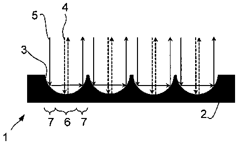
100391 Fig. 1 schematically shows a sectional representation through a
retroreflective microcavity structure 1 which is formed in a substrate. On its
upper
side, this substrate has several microcavities 3, which in the shown case are
configured as spherical depressions. The depressions are executed
reflectively, for
example through a suitable coating (not shown). The microcavities 3 act as
retroreflectors, i.e. they throw back radiation (e.g. light) in the direction
of
incidence. Fig. 1 shows the case of an incidence of radiation perpendicular to
the
surface of the substrate 2, Fig. 2 the situation for an oblique incidence.
CA 02814872 2013-04-16
-12-
100401 Radiation 4 incident in the center of each microcavity 3 is thrown back
to
the radiation source by single reflection. Radiation 5 incident at the edge of
the
microcavity 3, however, is deflected twice in the microcavity 3 and then
reflected
in the direction of the radiation source. Thus, there are two regions 6, 7 in
the
microcavity 3. Radiation incident in a first region 6 is directly reflected.
In a second
region 7, which in plan view of the surface annularly surrounds the first
region 6,
the radiation is deflected twice, however.
[0041] The regions 6 and 7 differ, however, primarily with respect to the
angle of
impingement at which the radiation impinges on the boundary area of each
microcavity 3. This is schematically represented in Fig. 3, which shows a
cross
section through a spherical microcavity 3. On the x-axis the radial coordinate
is
plotted. On the z-axis the height coordinate. The curve 8 shows the surface of
the
microcavity 3. In the region 6 this surface is symbolized by a dashed line, in
the
region 7 by a continuous line. It is well recognizable that at the radial
coordinates
between -7 and +7 the first region 6 is present - radiation incident there is
thus
reflected only once. Radiation incident at greater radial coordinates,
however, is
reflected twice. The impact on the angle of impingement is shown by curve 9,
for
which the right vertical axis applies at which the angle a is plotted, at
which the
radiation impinges on the surface of the microcavity 3. It can be clearly seen
that
the doubly reflected radiation, i.e. radiation that is incident in the second
region 7,
impinges at an angle of about 45 and greater on the surface.
[0042] For good order's sake it is pointed out that Fig. 3 reproduces the
situation
for a perpendicular incidence of the radiation. For oblique angles of
incidence, the
respective regions are somewhat shifted from the symmetry axis. The districts
7
with double beam reflection are present for a great range of angles of
incidence,
however.
CA 02814872 2013-04-16
- 13 -
[0043] The regions 6, 7, which differ with respect to the angle of impingement
a
with which the ultimately retroreflected radiation impinges on the surface of
the
microcavity 3, cooperate with a layer structure 13, which is applied on the
surface
of the microcavities 3. This is recognizable in Fig. 4, which shows a
sectional
representation of a security element 10 in a first embodiment. The security
element
is built up on a substrate 11, whereon an embossing lacquer 12 is applied.
Into
this embossing lacquer 12 there is formed, as already previously explained in
the
general part of the description, the microcavity structure 1, which has a
multiplicity
of adjacent microcavities 3. On the surfaces of the microcavities 3 there is
applied
the layer structure 13, the substantial feature of which is a dispersion
dependent on
the angle of incidence. The layer structure 13 therefore causes a color effect
still to
be explained. It can be executed, for example, as a known color-shift coating.
Such
coatings usually consist of a semi-transparent metal layer, a metallic mirror
layer
and a dielectric spacer layer located in between. They reflect light with a
color that
depends on the angle of incidence with which the radiation impinges on the
coating. Such color-shift coatings are known for planar areas, which show a
rainbow-like color effect when they are tilted upon viewing.
[0044] Above the such coated microcavity 3 there is applied a cover layer,
which
both fills the microcavities 3 at 14 and also planarly covers the microcavity
structure 1 by means of a superjacent section 15.
[0045] The Figures 5 and 6 illustrate how the depth of the microcavities 3 of
the
microcavity structure 1 can be correspondingly chosen. The depth has an impact
on
the size of the first region 6 as well as of the second region 7 surrounding
it. An
individual microcavity 3 is chosen, in a plan view of the surface of the
security
element 10, i.e. when viewed in the drawing plane of the Figures 4 to 7, such
that
no diffraction effects occur, on the one hand, and an individual microcavity 3
cannot yet be resolved with the unarmed eye, on the other hand. A region
between
2 gm and 300 gm fulfills this requirement. An individual microcavity 3 thus
acts as
CA 02814872 2013-04-16
-14 -
an individual pixel. The color that this pixel has depends on the layer
structure 13,
on the one hand, and on the size ratio between first region and second region,
on
the other hand. In the first region the layer structure 13 causes a first
color effect
due to the angles of incidence that are present in the first region 6. The
double run
through the layer structure 13 at a different angle of incidence in the second
region
7 results in a second color effect. Since the microcavities 3 are so small
that they
cannot be resolved with the eye, an individual microcavity 3 conveys as a
result to
the viewer a color impression that arises from the mixture of first and second
color
effect. The mix ratio is specified by the size ratio between first region 6
and second
region 7 and thus as a result by the geometry of the microcavity 3.
[0046] The security element 10, of course, is not limited to a microcavity
structure 1 with spherical depressions for the microcavities 3. Fig. 7 shows
by way
of example an aspherical depression structure for the microcavities 3.
[0047] Fig. 8 shows in a plan view the different area portions of the first
regions
6 (hatched from the bottom left to the top right) and of the second regions 7
(hatched from the bottom right to the top left) of the microcavities 3 in the
microcavity structure 1. A multiplicity of microcavities 3 with first regions
6 and
second regions 7 lie side by side. Each microcavity 3 acts as a pixel with the
already mentioned color mixture.
[0048] The color of each pixel can be adjusted through different geometries of
the microcavities 3 in the microcavity structure 1. This is schematically
represented
in den Figures 9 and 10. Fig. 9 shows a sectional representation corresponding
to
the Figures 4 to 7. Here, the microcavities are now designed with different
geometries. By way of example, four microcavities 3a, 3b, 3c and 3d are drawn,
whose depths increase. With increasing depth the portion which the first
region has
in the area of the microcavity to be seen in a plan view alters. Thus the area
ratios
between first region and second region alter. Fig. 10 shows accordingly that
the
CA 02814872 2013-04-16
=a .
- 15 -
area ratio between first region 6a and second region 7a at the flatest
microcavity 3a
is different than at the somewhat deeper microcavity 3b, the significantly
deeper
microcavity 3c, or the deepest microcavity 3d. Thus, the mix ratio, which
ensues
between first and second color effect, is different for the four microcavities
3a to 3d
and each microcavity conveys to a viewer a different color impression. This
makes
it possible to design motifs in simple fashion, because only the geometry of
the
microcavities 3 must be varied in the manufacturing process, e.g. by different
exposure intensities in the photolithographic process. The layer structure 13,
however, does not have to be varied, it can remain identical for all
microcavities 3
of the microcavity structure 1, which is very advantageous from a
manufacturing
point of view.
[0049] The employment of microcavity structures 1 that act as retroreflectors,
however, is not limited to rotationally symmetric microcavities. These have
the
property that the optical effect in two spatial directions is independent of
the
viewing direction, but also the employment of retroreflectors that only in one
spatial direction are insensitive to variations of the viewing direction can
achieve a
very forgery-resistant security element 10.
[0050] The plan view of a corresponding microcavity structure 1 is shown in
Fig.
11. Here, the microcavities 3 are now configured as elongate grooves, which
lie
side by side. In Fig. 11 there is drawn, for clarity's sake, a border 16
between two
neighboring microcavities 3. The microcavity 3 corresponds in a section, that
extends vertically in the representation of Fig. 4, to the views as they were
shown
in the Figures 4 to 7 and 9. In the horizontal direction the microcavities are
configured as elongate grooves. In this direction they are so long that they
can be
resolved with the unarmed eye. This is not compulsory, however. The length of
at
least some grooves can also lie below the recognizability limit.
CA 02814872 2013-04-16
- 16 -
[0051] Such a microcavity structure now allows to adjust a color between a
motif
and its background, which color depends on the viewing direction. Such a
security
element 10 is represented by way of example in Fig. 12. It comprises regions
17, in
which the direction along which the microcavities 3 extend, is for example
horizontal.
[0052] In regions 18, however, the longitudinal direction of the channel-
shaped
microcavities 3 is vertical. The cavities of the motif are thus oriented with
their
main direction perpendicular to the cavities of the background. Each
microcavity is
now coated such that the pattern upon oblique viewing appears in two colors.
Depending on the viewing direction, there is now realized a different color
effect,
because only for one of the two districts 17 and 18 there occurs the above-
mentioned color mixture. If the security element is rotated in the viewing
plane by
90 , a color exchange occurs between pattern and background, i.e. between
first
district 17 and second district or second districts 18.
[0053] The Figures 13 and 14 show that a different orientation of non-
rotationally symmetric microcavities 3 is, of course, not limited to mutually
perpendicular arrangements. By a continuous variation of the longitudinal
direction
of such non-rotationally symmetric microcavities 3 there can also be realized
pump
and run effects. Fig. 13 shows a security element 10 whose microcavity
structure 1
is formed by microcavities extending in star-shaped fashion. Fig. 14 serves as
a
proof of the fact that the microcavities can also be executed in non-straight
fashion.
In the Figure they are circular by way of example.
[0054] Fig. 15 finally shows a plan view of a microcavity structure 1, which
comprises regions 17 to 26, in which the longitudinal direction of the channel-
shaped microcavities 3 is varied by 10 relative to the respective next
district. The
borderlines between the districts are shown in the drawing only for
illustration,
here.
CA 02814872 2013-04-16
. .
- 17 -
List of reference signs
1 microcavity structure
2 substrate
3 microcavity
4 light beam
light beam
6 first region
7 second region
8, 9 curve
security element
11 substrate
12 embossing lacquer
13 layer structure
14, 15 cover layer
16 border
17 to 26 district