Note: Descriptions are shown in the official language in which they were submitted.
CA 02815499 2013-04-22
WO 2012/054603
PCT/US2011/056886
NASOGASTRIC TUBE FOR USE DURING AN ABLATION PROCEDURE
FIELD OF THE INVENTION
Embodiments of the present invention relate generally to a nasogastric tube
and, more particularly, to a nasogastric tube for deflecting the esophagus and
monitoring various properties of the esophagus during an ablation procedure.
BACKGROUND OF THE INVENTION
Esophageal tubes, probes, balloons, and other devices have been used to
monitor internal physiologic function, decompress all portions of the
alimentary tract,
and protect the airway in sedated patients undergoing surgical procedures. It
is
currently common medical practice to use a nasogastric tube in most patients
requiring mechanical ventilation during surgical procedures, and to use a
nasogastric
tube to mark the anatomic relationships between the left atrium and the
esophagus in
patients undergoing atrial fibrillation ablation with general anesthesia and
or
conscious sedation procedures. Marking the esophagus during atrial
fibrillation (left
atrial) ablation has gained prominence because of the occurrence of unintended
esophageal heat injury.
Various ablation techniques, such as high-energy microwaves,
radiofrequency, and cryogenic methods, have been used to create a focal tissue
lesion in the atrium to treat atrial dysrhythmias and atrial fibrillation.
Common left
atrial ablation techniques include wide circumferential lesions encircling the
pulmonary veins and linear lesions on the posterior left atrium, mitral
isthmus, and
left atrium roof. The esophagus and posterior left atrial wall are located
proximate to
one another (see FIG. 1) and near the ablation zone for left atrial ablation
and
pulmonary vein isolation. Studies have shown that the mean length and width of
the
esophagus in contact with the posterior left atrium are 5.8 centimeters and
1.36
centimeters, respectively. Although most patients have a small fat pad
separating
the posterior left atrium and esophagus, this fat pad is often discontinuous.
Due to
-1-
CA 02815499 2013-04-22
WO 2012/054603
PCT/US2011/056886
the close proximity of the esophagus and the left atrium, ablation along the
posterior
left atrium may result in unintended thermal injury to the esophagus and
subsequent
fatal esophageal-atrial fistula presenting as a fatal complication 1-3 weeks
following
left atrial ablation. An esophageal-atrial fistula can cause an air embolism
with a
stroke, mediastinitis, GI bleeding , and have high mortality rates.
Different techniques have been used to monitor the temperature and position
of the esophagus during ablation of the atrium. Strategies to avoid esophageal
injury
resulting from left atrial ablation include: avoidance of energy delivery at
close
esophageal atrial sites, decreased ablative energy and duration of energy
delivery
(time) at target sites, use of intracardiac echo and other imaging techniques
to avoid
unsafe ablative sites, and esophageal temperature monitoring to recognize
esophageal heating. However, these precautionary approaches have proven to be
unreliable and/or likely to compromise the ablation procedure.
The anterior wall of the esophagus is separated from the posterior wall of the
left atrium and/or the proximal pulmonary vein by 0 to 4 millimeters of fat
and the
oblique sinus recess of the pericardium. The separation distance between the
anterior wall of the esophagus and the posterior wall of the left atrium
becomes even
less during phases of peristalsis of the esophageal musculature. The esophagus
is a
mobile organ that allows movement and adjusts to thoracic and diaphragmatic
motion independent of the heart. Esophageal mobility is limited to some degree
by
venous connections and drainage of the esophagus, azyis vein and loose
attachments to the mediastinal connective tissue. As a result, static imaging
techniques are inadequate to monitor the position of the esophagus due to the
mobility of the esophagus. Thus, real-time imaging techniques, such as
intracardiac
echocardiography, may be more effective in monitoring the variable esophageal
and
left atrial anatomic relationship due to mobility and peristalsis of the
esophagus.
An alternative approach to avoid injury to the esophagus has been to deflect
the esophagus away from the ablation site, such as by moving the esophagus one
centimeter or more from the ablation site. Transesophageal echo probes have
been utilized
in attempts to deflect or mobilize the retrocardiac portion of the esophagus
away from
ablation sites, but have had limited success due to the bulkiness of the
device and
the inability of the curved distal tip of the probe to effectively deflect the
esophagus.
Attempts to excessively mobilize the esophagus need to be avoided, but gentle
and
defuse intraluminal deflection of 0.5 to 3.0 cm is within the physiologic
range.
Therefore, there is a need for a nasogastric tube for deflecting the retro-
cardiac esophagus to reduce the incidence of thermal injury of the esophagus
due to
an ablation procedure. In addition, there is a need for techniques to monitor
the
-2-
CA 02815499 2013-04-22
WO 2012/054603
PCT/US2011/056886
esophagus during an ablation procedure to identify and avoid thermal injury to
the
esophagus. Additional applications include control of the esophagus during
radio-
therapy for lung tumors.
SUMMARY OF THE INVENTION
Embodiments of the present invention provide a nasogastric tube and method
of using the same for deflecting an esophagus during an ablation procedure,
such as
left atrial ablation for treating atrial fibrillation. The nasogastric tube
includes one or
more lumens for receiving an esophageal deflector that is configured to
deflect the
esophagus away from the ablation site and within the physiological range
during an
ablation procedure so as to reduce the incidence of thermal injury to the
esophagus.
Furthermore, embodiments of the present invention provide a nasogastric tube
that
includes a plurality of lumens that are configured to receive one or more
instruments
to monitor the position and/or physical properties of the esophagus during an
ablation
procedure, as well as assist in positioning the nasogastric tube in the
esophagus.
Visualizing and monitoring various properties of the target area during
ablation can
provide a technique to avoid thermal esophageal injury.
According to one embodiment, the nasogastric tube includes a tube
comprising at least one lumen having proximal and distal ends, and an
esophageal
deflector (e.g., a pull-wire apparatus) positioned within the lumen and
configured to
deflect a portion of the tube between the proximal and distal ends. The
esophageal
deflector is configured to deflect the portion of the tube proximate to a
retrocardiac
portion of the esophagus such that the retrocardiac portion of the esophagus
is
deflected away from an ablation site. For example, the esophageal deflector
may be
configured to deflect the retrocardiac portion of the esophagus during a left
atrium
ablation procedure and/or deflect and hold the retrocardiac portion of the
esophagus
laterally or posteriorly.
Aspects of the nasogastric tube include a nasogastric tube having a plurality
of lumens. Each of the plurality of lumens may be configured to receive a
pressure
transducer, a temperature recorder, an electrogram recorder, an
electroanatomic
positioning apparatus, a balloon or balloons, a guide wire, and/or a syringe.
According to one embodiment, one of the lumens is configured to receive an
expandable basket. The expandable basket may include a plurality of
thermisters
and a plurality of electrodes. In addition, the nasogastric tube may include
an
opening between its proximal and distal ends, wherein at least a portion of
the basket
is configured to expand out of the opening , proximate or adjacent to the
esophagus.
Additional aspects include a nasogastric tube comprising an elastomeric
material.
-3-
CA 02815499 2013-04-22
WO 2012/054603
PCT/US2011/056886
The esophageal deflector may be configured to deflect the tube along a length
of
about 4 to 10 cm and/or to deflect a portion of the tube to a radius of about
0.5 to 4
cm. Moreover, at least a portion of the esophageal deflector may be
fluoroscopically
visible.
Another embodiment of the present invention provides a nasogastric tube
having a tube comprising a plurality of lumens each having proximal and distal
ends.
The nasogastric tube also includes an esophageal deflector positioned within
one of
the plurality of lumens and configured to deflect a portion of the tube
between the
proximal and distal ends. In addition, the nasogastric tube includes at least
one
instrument positioned within one of the plurality of lumens and configured to
monitor
the position of the esophagus during an ablation procedure, monitor one or
more
physical properties of the esophagus during an ablation procedure, and/or
assist in
positioning the tube within the esophagus.
Moreover, one embodiment of the present invention provides a method for
deflecting the esophagus during an ablation procedure. The method includes
inserting a nasogastric tube into the esophagus, wherein the nasogastric tube
comprises at least one lumen having proximal and distal ends and an esophageal
deflector positioned within the at least one lumen. The method further
includes
actuating the esophageal deflector so as to deflect a portion of the tube
between the
proximal and distal ends and proximate to a retrocardiac portion of the
esophagus
such that the retrocardiac portion of the esophagus is deflected away from an
ablation site.
Various aspects of the method include inserting a nasogastric tube having a
plurality of lumens into the esophagus. The method may further include
inserting an
expandable basket, a pressure transducer, a temperature recorder, an
electrogram
recorder, an electro-anatomic positioning apparatus, a balloon, a guide wire,
and/or a
syringe into one of the plurality of lumens. Furthermore, the deflecting step
may
include deflecting the retrocardiac portion of the esophagus during a left
atrium
ablation procedure and/or deflecting the retrocardiac portion of the esophagus
laterally or posteriorly. The inserting step could include inserting the
nasogastric tube
such that the nasogastric tube extends from a proximal end of the esophagus to
a
distal end of the esophagus or to the gastric fundus.
Another embodiment of the present invention is directed to a nasogastric tube
for deflecting an esophagus during an ablation procedure. The nasogastric tube
comprises a flexible tube including at least one lumen having proximal and
distal
ends and an esophageal deflector (e.g., a flexible rod or wire) positioned
within the at
least one lumen. At least one opening may be defined in a sidewall of the tube
-4-
CA 02815499 2013-04-22
WO 2012/054603
PCT/US2011/056886
between its proximal and distal ends, wherein the opening is configured to
receive a
diagnostic device there through. The esophageal deflector is configured to be
mechanically actuated to assume a curved profile so as to deflect a portion of
the
tube between the proximal and distal ends, wherein the esophageal deflector is
configured to deflect the portion of the tube proximate to a retrocardiac
portion of the
esophagus such that the retrocardiac portion of the esophagus is deflected
away
from an ablation site. In one aspect, the esophageal deflector may be
configured to
deflect the tube along a length of about 10 to 15 cm.
According to aspects of the nasogastric tube, the flexible tube comprises at
least one inflatable balloon proximate to its distal end configured to anchor
the
esophageal deflector in the esophagus. In one aspect, the flexible tube
comprises a
plurality of inflatable balloons proximate to its distal end configured to
anchor the
esophageal deflector in the esophagus. The esophageal deflector may be
configured to be mechanically actuated by an axial force so as to assume the
curved
profile. The esophageal deflector may include an angulated distal tip
configured to
engage the tube proximate to the distal end. The flexible tube may include a
groove
configured to receive the angulated tip therein so as to secure the angulated
tip
therein. The esophageal deflector may have a non-curved profile in a relaxed
state
such that the curved profile is not preformed.
In one aspect, the esophageal deflector varies in at least one of thickness or
density along its length. The esophageal deflector may include a proximal
portion of
uniform thickness or density, an intermediate portion of varying thickness or
density,
and a distal portion of uniform thickness or density. The esophageal deflector
may
have various dimensions such as, for example, a proximal portion of about 15-
25 cm
in length, an intermediate portion of about 10-15 cm in length, and a distal
portion of
about 2-6 cm in length. The esophageal deflector may alternatively include a
plurality of different types of materials, each material exhibiting a
different stiffness.
The esophageal deflector may include a polymeric material, while the flexible
tube
may include an elastomeric material.
In one embodiment, a method for deflecting an esophagus during an ablation
procedure is provided. The method includes inserting a nasogastric tube into
the
esophagus, wherein the nasogastric tube comprises at least one lumen having
proximal and distal ends and an esophageal deflector positioned within at
least one
lumen, and mechanically actuating the esophageal deflector to assume a curved
profile so as to deflect a portion of the tube between the proximal and distal
ends and
proximate to a retrocardiac portion of the esophagus such that the
retrocardiac
portion of the esophagus is deflected away from an ablation site. In one
aspect, the
-5-
CA 02815499 2013-04-22
WO 2012/054603
PCT/US2011/056886
mechanically actuating step includes applying an axial force to the esophageal
deflector (e.g., applying an axial force in a distal direction). The method
may further
include anchoring the nasogastric tube in the esophagus with at least one
inflatable
balloon proximate to the distal end thereof.
BRIEF DESCRIPTION OF THE DRAWINGS
Having thus described various embodiments of the invention in general terms,
reference will now be made to the accompanying drawings, which are not
necessarily
drawn to scale, and wherein:
FIG. 1 shows a lateral view of the anatomic arrangement of the esophagus,
heart, and pulmonary veins with respect to one another;
FIG. 2 illustrates a side view of a nasogastric tube according to one
embodiment of the present invention;
FIGS. 3A-3B depict an esophageal deflector according to one embodiment of
the present invention;
FIG. 4 illustrates an expandable basket according to an embodiment of the
present invention;
FIGS. 5A-5E show cross-sectional views of the nasogastric tube shown in
FIG. 1;
FIG. 6 illustrates a nasogastric tube deflecting the esophagus according to
one embodiment of the present invention;
FIG. 7 is a side view of a nasogastric tube according to another embodiment
of the present invention;
FIG. 8 illustrates a nasogastric tube deflecting the esophagus according to
another embodiment of the present invention;
FIGS. 9A-C are cross-sectional views of a flexible rod according to one
embodiment of the present invention; and
FIG. 10 is an enlarged side view of an angulated tip engaging a groove
defined in the tube according to one embodiment of the present invention.
DETAILED DESCRIPTION
The present inventions now will be described more fully hereinafter with
reference to the accompanying drawings, in which some, but not all embodiments
of
the invention are shown. Indeed, this invention may be embodied in many
different
forms and should not be construed as limited to the embodiments set forth
herein;
rather, these embodiments are provided so that this disclosure will satisfy
applicable
legal requirements. Like numbers refer to like elements throughout.
-6-
CA 02815499 2013-04-22
WO 2012/054603
PCT/US2011/056886
Referring to FIG. 2, there is shown a nasogastric tube 10 according to one
embodiment of the present invention. In general, the nasogastric tube 10
includes at
least one lumen 14 for receiving an instrument therein. According to one
embodiment, an esophageal deflector 12 is positioned within the lumen 14 and
is
configured to deflect the esophagus during an ablation procedure. For example,
the
esophageal deflector 12 may be configured to deflect a portion of the
nasogastric
tube 10 proximate to a retrocardiac portion of the esophagus such that the
retrocardiac portion of the esophagus is deflected away from an ablation site.
Deflecting the esophagus away from the ablation site may reduce the incidence
of
thermal injury of the esophagus during ablation procedures, such as left
atrial
ablation.
Although the term "nasogastric" is used herein as describing a nasogastric
tube 10 that is configured to be inserted through the nose or throat into the
esophagus during an ablation procedure, it is understood that the nasogastric
tube
could be positioned within various body cavities for displacing a portion of
the
anatomy. Moreover, the nasogastric tube 10 may be a variety of materials, such
as a
polymeric material (e.g., polyurethane). According to one embodiment, the
nasogastric tube 10 is a flexible elastomeric material, such as silicone. In
addition,
the nasogastric tube 10 may be a variety of sizes and configurations depending
on its
use. For example, the outer diameter of the nasogastric tube 10 may be about 5-
10
mm, and/or the nasogastric tube could have a tapered atraumatic tip. The
nasogastric tube 10 may also be various lengths and may, for example, extend
from
the nose or throat and caudally to the distal esophagus and/or gastric fundus.
FIGS. 2 and 5A-5E illustrate that the nasogastric tube 10 includes a plurality
of lumens 14 (e.g., six lumens), although a single lumen could be used if
desired.
According to one embodiment, a central tube includes a plurality of smaller
tubes
slidably or securely positioned therein that define respective lumens 14.
Alternatively, the central tube could have a plurality of lumens 14 defined
therein,
such as by integrally forming the lumens via molding. Each lumen 14 is
configured to
receive one or more instruments therein. The instruments could be used to
monitor
the position and/or physical properties of the esophagus during an ablation
procedure, as well as assist in positioning the nasogastric tube 10 in the
esophagus.
Various instruments could be inserted within the lumens 14, such as a pressure
transducer, a temperature recorder, an electrogram recorder, an
electroanatomic
positioning apparatus, a balloon, a guide wire, or a syringe. For example,
monitoring
instruments may be used for fluoroscopic visualization, adjacent wall
temperature
monitoring, intraesophageal temperature mapping, magnetic and/or
electroanatomic
-7-
CA 02815499 2013-04-22
WO 2012/054603
PCT/US2011/056886
3D mapping, cardiac electrogram pacing and recording, and the like, of the
esophagus, such as the retrocardiac portion of the esophagus. According to one
embodiment, the nasogastric tube 10 is configured to receive a pressure
transducer
in one of the lumens 14 that includes a semi-conductor chip having a piezo-
resistive
pressure diaphragm that facilitates monitoring of pressure applied to the
esophagus,
such as pressure applied when deflecting the retrocardiac portion of the
esophagus,
as explained in further detail below. Also, one or more of the lumens 14 can
be used
for providing and/or removing fluids and may be connected to a syringe
suction/infusion device. Moreover, one or more of the lumens 14 could be left
open
such that different instruments may be inserted and removed from the lumens
during
an ablation procedure.
According to one embodiment, one of the lumens 14 is configured to receive
a guide wire 18 to facilitate nasal-oral passage of the nasogastric tube 10
into the
esophagus. For example, the guide wire 18 could be inserted through the nose
or
throat and into the esophagus and passed caudally to the distal esophagus
and/or
gastric fundus so as to facilitate placement of the nasogastric tube 10 in the
esophagus. The guide wire 18 could be guided via fluoroscopy and/or by feel.
The
guide wire 18 could be removable and may extend from the proximal end of the
nasogastric tube 10 and distally of the distal end of the nasogastric tube. In
addition,
the guide wire 18 is typically flexible and may be manually curved and/or
deflectable
using a pull-wire mechanism.
A lumen 14 of the nasogastric tube 10 may also be configured to receive an
inflatable balloon 20. In particular, the inflatable balloon 20 may be
positioned
proximate to a distal end of the nasogastric tube 10 so that the balloon may
be
expanded to fix the nasogastric tube in position. In particular, the
inflatable balloon
20 may be inflated to fix or tether the nasogastric tube 10 on the gastric
side of the
gastro-esophageal sphincter to provide additional stability and facilitate
deflection of
the esophagus and reduce or eliminate esophageal reflux thereby decreasing the
potential for aspiration.
Furthermore, one of the lumens 14 is configured to receive an esophageal
deflector 12, as shown in FIGS. 2 and 3A-3B. The esophageal deflector 12 is
configured to deflect a portion of the tube between the proximal and distal
ends. For
example, the esophageal deflector 12 may be configured to create a gentle C-
shaped curve of a portion of the nasogastric tube 10. In addition, the
esophageal
deflector 12 is configured to deflect the tube along a length of about 4 to 10
cm and
to a radius of about 0.5 to 4 cm, although the esophageal deflector is capable
of
deflecting the nasogastric tube along various lengths and to various radii if
desired.
-8-
CA 02815499 2013-04-22
WO 2012/054603
PCT/US2011/056886
According to one embodiment, the esophageal deflector 12 is configured to
deflect a portion of the nasogastric tube 10 proximate to a retrocardiac
portion of the
esophagus such that the retrocardiac portion of the esophagus may be deflected
away from an ablation site, such as during a left atrium ablation procedure.
For
example, the esophageal deflector 12 could be used to deflect the nasogastric
tube
in order to apply pressure to the posterior and posterior lateral internal
esophageal wall thereby pulling the anterior and anteriolateral wall of the
esophagus
away from the posterior left atrial ablation site (see FIG. 6). According to
one
embodiment, the esophageal deflector 12 is configured to separate the anterior
wall
10 of the esophagus about 3 to 8 mm from the posterior left atrial ablation
site.
Furthermore, the nasogastric tube 10 and/or esophageal deflector 12 may be
rotated
so that the curved pressure applied to the retrocardiac portion of the
esophagus may
be deflected in any direction from the left-atrial, left-ventricle sites. In
other words,
the esophagus may be moved posterior, posterior right lateral, or posterior
left lateral
in relationship to the position of an intracardiac ablation electrode.
Moreover, at least a portion of the nasogastric tube 10 and/or esophageal
deflector 12 may be fluoroscopically visible in order to facilitate
positioning within the
esophagus. In addition, the nasogastric tube 10 and/or esophageal deflector 12
may
include one or more radiopaque markers 24 that facilitate radiographic and/or
electroanatomic positioning and/or deflection of the esophagus. The
nasogastric
tube 10 and/or esophageal deflector 12 may include one or more thermisters for
measuring and/or monitoring temperature changes and localizing the position of
the
electrode used in an ablation procedure in relation to the ablation site
(e.g., left
atrium).
According to one embodiment of the present invention, the esophageal
deflector 12 includes a pull-wire apparatus 22. The pull wire apparatus 22 may
be
integrated into the nasogastric tube 10 or one of the lumens 14 within the
nasogastric
tube and is configured to deflect a portion of the nasogastric tube, such as
into a C-
shaped curve. For example, FIG. 3A illustrates that the pull wire apparatus 22
may
include a pair of rings 26, 27 coupled to first 28 and second 30 wires. In
particular a
first pull wire 28 extends from an actuator (not shown) or proximal end of the
nasogastric tube 10 and attaches to a first ring 27, while the second pull
wire 30
extends between the pair of rings 26, 27. As the actuator, such as a rotatable
handle
or slidable trigger, actuates the first pull wire 28 by pulling the pull wire
proximally, the
second pull wire 30 deflects outwardly as shown in FIG. 3B. Thus, the second
pull
wire 30 may be a flexible material that is capable of deflecting outwardly and
is of
sufficient rigidity to deflect the nasogastric tube 10 outwardly. It is
understood that
-9-
CA 02815499 2013-04-22
WO 2012/054603
PCT/US2011/056886
various pull-wire apparatus and other techniques could be used to deflect the
nasogastric tube 10. For example, the esophageal deflector 12 could include a
single wire that may be pushed distally within the lumen 14 and then bow
outwardly
at its distal end or that is a semi-rigid bent wire.
FIGS. 2 and 4 show that the nasogastric tube 10 is configured to receive an
expandable basket 16. The expandable basket 16 includes a plurality of
flexible
arms 32 having respective thermisters 34 and electrodes 36. For example, there
may be 3-5 flexible arms 32, although any number of arms could be used to
provide
three-dimensional expansion. The flexible arms 32 are fixed at their proximal
ends
with a proximal tube 40 and fixed at their distal ends with a distal tube 42.
The
proximal tube 40 is typically longer than the distal tube 42, while the distal
tube may
be, for example 2-4 cm in length. An opening 38 is defined in a portion of the
nasogastric tube 10 between the proximal and distal ends, and at least a
portion of
the expandable basket 16 is configured to expand out of the opening and
proximate
to the esophagus. Thus, as shown in FIG. 2, the expandable basket 16 is
positioned
within the lumen 14 prior to being moved distally so as to expand out of the
opening
38, as illustrated in FIG. 4. Thus, the flexible arms 32 may comprise a memory
material that is configured to bias outwardly of the opening 38, as well as
inwardly as
the arms are moved proximally within the lumen 14. In addition, the amount of
expansion of the expandable basket 16 may be adjusted by moving the expandable
basket proximally or distally. For instance, moving the expandable basket 16
to align
with the opening 38 provides full expansion, while the expandable basket may
be
incrementally moved proximally in order to reduce the amount of expansion. The
expandable basket 16 may be deployed at various times during an ablation
procedure, including when the nasogastric tube 10 is deflected.
The lumen 14 for receiving the expandable basket 16 may be positioned in
the cephlad extra oral portion of the nasogastric tube 10. The opening 38 may
be
defined proximate to the portion of the tube that may be deflected in the
retrocardiac
portion of the esophagus, such as just below the tracheal bifurcation and
extending
5-8 cm. Thus, the flexible arms 32 are configured to bias outwardly to contact
the
esophageal wall, but preferably do not independently deflect or expand the
esophagus. There may be any number of thermisters 34 per flexible arm 32
(e.g., 3-
9) in order to obtain circumferential temperature measurements. Furthermore,
there
may be any number of electrodes 36 (e.g., 4-10) that are configured to provide
electrogram and/or positional measurements. In one embodiment, the electrodes
36
may be used for recording electrical data from the heart and/or pacing the
heart.
Thus, the expandable basket 16 may provide various measurements
simultaneously,
-10-
CA 02815499 2013-04-22
WO 2012/054603
PCT/US2011/056886
as well as concurrently with similar measurements obtained within the atrium
or
ventricle via intracardiac monitoring. Moreover, the expandable basket 16 may
be
used during an ablation procedure, such as left atrial ablation, so that the
temperature and position of the esophagus may be monitored in order to reduce
the
incidence of thermal injury to the esophagus. For example, if the temperature
of the
esophagus is approaching a dangerous level, the power to the electrode may be
reduced or the esophagus further deflected or moved to avoid thermal injury to
the
esophagus.
During use according to one embodiment of the present invention, a
physician inserts a nasogastric tube 10 into the esophagus, typically via the
nose or
throat. The physician could utilize a guide wire 18 to facilitate insertion of
the
nasogastric tube 10 within the esophagus. The nasogastric tube 10 could be
inserted such that the nasogastric tube extends from a proximal end of the
esophagus to a distal end of the esophagus or a gastric fundus. The distal end
of the
nasogastric tube 10 could be anchored via an inflatable balloon for further
stabilization. Once properly positioned within the esophagus, the physician
may
actuate the esophageal deflector 12 so as to deflect a portion of the
nasogastric tube
10 between the proximal and distal ends and proximate to a retrocardiac
portion of
the esophagus such that the retrocardiac portion of the esophagus is deflected
away
from an ablation site. The physician may also employ various other instruments
while the esophagus is deflected or non-deflected, such as expandable basket
16, a
pressure transducer, a temperature recorder, an electrogram recorder, an
electroanatomic positioning apparatus, a balloon, a guide wire, and/or a
syringe. The
esophageal deflector 12 is configured to deflect the retrocardiac portion of
the
esophagus during a left atrium ablation procedure, as well as deflect the
retrocardiac
portion of the esophagus laterally or posteriorly while an ablation procedure
is being
performed. For instance, the esophageal deflector 12 could deflect the
esophagus
away from the ablation electrode during an ablation procedure.
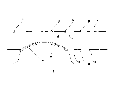
FIGS. 7-10 illustrate another embodiment of the present invention. FIG. 7
shows a nasogastric tube 100 also configured to deflect the esophagus during
an
ablation procedure. The nasogastric tube 100 comprises a flexible tube 102
similar
to that described above, which is capable of receiving an esophageal deflector
104
therein and deflecting in response to actuation of the esophageal deflector.
The tube
102 can have a substantially uniform diameter and cross section along its
length (see
e.g., FIG. 8) or different diameters and/or cross sections (see e.g., FIG. 7).
The
flexible tube 102 includes at least one lumen for receiving the esophageal
deflector
104 therein and allowing for axial displacement therethrough.
-11-
CA 02815499 2013-04-22
WO 2012/054603
PCT/US2011/056886
The tube 102 may include one or more inflatable balloons 106 coupled
proximate to its distal end to facilitate fixation with the esophagus. The
tube 102 may
also include at least one opening 108 defined in its sidewall between its
proximal and
distal ends, which is configured to receive a diagnostic device therethrough.
For
example, the opening may allow a physician to insert a diagnostic device
proximate
to the heart, such as to determine temperature and/or provide electrocardiac
mapping and/or pacing. In one embodiment, the opening may be located about 8-
12
cm (e.g., 10 cm) above the proximal most inflatable balloon 106.
The esophageal deflector 104 is configured to be mechanically actuated to
assume a curved profile so as to deflect a portion of the tube 102 between the
proximal and distal ends. Although the term "curved" is used herein, this
usage is not
intended to be limiting, as a curved profile may be any profile that is not
straight or of
a shape sufficient to deflect the esophagus. In one embodiment, the esophageal
deflector 104 has an initial profile in a relaxed state having a different
radius of
curvature or shape than the curved profile. Thus, the curved profile is not
preformed
but, rather, is formed by mechanically actuating or otherwise manipulating the
esophageal deflector 104. For example, the esophageal deflector 104 may have a
substantially straight or non-curved profile in a relaxed state and be
sufficiently
flexible to assume the contours of the esophagus when being inserted therein.
Moreover, the esophageal deflector 104 may be a flexible rod or wire that is
configured to flex when mechanically actuated to assume a curved profile and
to
return to its original state upon being no longer mechanically actuated. For
example,
the esophageal deflector 104 may be mechanically actuated by applying an axial
force in a distal direction. In addition, the esophageal deflector 104 may
include a
handle 114 at its proximal end for a physician to manipulate the deflector as
necessary.
In order to facilitate the mechanical actuation of the esophageal deflector
104,
the esophageal deflector may have an angulated tip 112 at its distal end that
is
configured to engage a groove 110 or opening defined in the tube 102. FIGS. 8
and
10 illustrate this concept where the angulated tip 112 is inserted within the
groove
110 so as to be secured therein. When secured within the groove 110 by
placement
of the angulated tip 112 therein, an axial force applied in the distal
direction will
cause the esophageal deflector to assume a curved profile since the angulated
tip
resists distal movement of the esophageal deflector with respect to the tube
102.
Thus, the position of the distal end of the esophageal deflector 112 is fixed
or
otherwise anchored so as to facilitate the formation of the curved profile
when an
axial force is applied thereto. In one exemplary embodiment, the angulated tip
112 is
-12-
CA 02815499 2013-04-22
WO 2012/054603
PCT/US2011/056886
about 0.01-0.10 cm in length, and in one particular embodiment is about 0.05
cm in
length.
FIGS. 9A-C also demonstrate that the esophageal deflector 104 may have
varying thickness and/or density along its length to in order to influence the
stiffness
and bending properties. FIG. 9A is a cross section of a proximal portion
("I"), FIG. 9B
is a cross section of an intermediate portion ("II"), and FIG. 9C is a cross
section of a
distal portion ("Ill") (see FIG. 10). For instance, the proximal portion may
be of
uniform thickness or density, the intermediate portion may be of varying
thickness or
density, and the distal portion may be of uniform thickness or density (see
FIGS. 8
and 9A-C). FIG. 9B demonstrates that one side of the intermediate portion
could be
formed of a thicker or denser material than another side such that the
esophageal
deflector 104 would tend to bend in the direction of the thicker or denser
material.
According to another aspect, the esophageal deflector 104 may be formed of
a plurality of different types of materials, wherein each material exhibits a
different
stiffness. For example, the intermediate portion of the esophageal deflector
104
could be formed of a more flexible material than the proximal and distal
portions.
Alternatively, the intermediate portion could be formed of different types of
materials
such that the arrangement of the materials facilitates flexing thereof.
The intermediate portion may be located proximate the heart and be
configured to assume a curved profile in response to mechanical actuation of
the
esophageal deflector 104. In one embodiment, the proximal portion is about 15-
25
cm in length, the intermediate portion is about 10-15 cm in length, and the
distal
portion is about 2-6 cm in length. In another embodiment, the proximal portion
is
about 20 cm in length, the intermediate portion is about 10-15 cm in length,
and the
distal portion is about 4 cm in length. As discussed above, the esophageal
deflector
may be formed of different types of materials, such as a polymeric material.
Moreover, the physician may be provided with a "kit" of esophageal deflectors
104
such that different sized deflectors could be used for different patients.
According to
one embodiment, the ease of which the esophagus may be deflected can be
facilitated by rotating the patient (e.g., 20-40 ) to the left or the right to
decrease the
weight of the heart on the esophagus.
Therefore, embodiments of the present invention may provide several
advantages. For example, one embodiment of the present invention provides a
nasogastric tube 10 that is configured to deflect the esophagus during an
ablation
procedure, such as left atrial ablation, thereby reducing the potential for
thermal
injury to the esophagus. The nasogastric tube 10 includes an esophageal
deflector
12 that is configured to deflect the retrocardiac portion of the esophagus,
which is
-13-
CA 02815499 2013-04-22
WO 2012/054603
PCT/US2011/056886
proximate to the posterior left atrial wall and susceptible to thermal injury
during an
ablation procedure. A physician is also able to manipulate the nasogastric
tube 10 in
response to peristaltic movement of the esophagus and while performing an
ablation
procedure. The nasogastric tube 10 may also include one or more lumens 14 for
receiving various instruments to monitor the position and/or physical
properties of the
esophagus during an ablation procedure, as well as assist in positioning the
nasogastric tube in the esophagus, which provides additional safeguards to
avoid
injury to the esophagus, as well as assist the physician during an ablation
procedure.
Many modifications and other embodiments of the invention set forth herein
will come to mind to one skilled in the art to which this invention pertains
having the
benefit of the teachings presented in the foregoing descriptions and the
associated
drawings. Therefore, it is to be understood that the invention is not to be
limited to
the specific embodiments disclosed and that modifications and other
embodiments
are intended to be included within the scope of the appended claims. Although
specific terms are employed herein, they are used in a generic and descriptive
sense
only and not for purposes of limitation.
-14-