Note: Descriptions are shown in the official language in which they were submitted.
CA 02815623 2016-08-18
W02011/058369 PCT/GB2010/051891
1
=
1 Remote Environment Inspection Apparatus end Method
2
3 The present invention relates to non-destructive testing, and in
particular to a method and
4 apparatus for the inspection of electrically conductive components.
Applications of the
invention include the inspection of tubular components that are often remotely
located
6 within the oil and gas exploration and production industries.
7
8 A variety of components are employed within the all and gas industry,
such as casings,
9 production tubing, pipelines, flexible risers and steel wire ropes. In
order to monitor the
structural integrity of these components a variety of non-destructive testing
techniques are
11 known for the detection and identification of defects and/or fatigue in
the external wall of
12 these tubular components.
13
14 One such non-destructive testing technique known In the art is
ultrasound inspection, for
16 example as described in US patent no. 4162635 or US patent publication
no.
16 US 2008/0313915. The ultrasound signal Is transmitted into the tubing
wall, and analysis
17 of the signal reflected from the opposing well allows information on the
wall thickness to be
18 derived, A number of different ultrasonic tools and methods are
available, but there are
19 drawbacks and deficiencies associated with their operation. Firstly,
ultrasonic tools
CA 02815623 2016-08-18
W02011/058369 PCT/GB2010/05 89
2
1 operating according to the contact method require good coupling between
the contact
2 transducers and the test object, and the large mismatch in the acoustic
impedance of air
3 and the acoustic impedance of the test material must be overcome. This
requires the use
4 of a coolant, for example a liquid or gel-like material that has a low
acoustic impedance
6 mismatch and therefore good acoustic coupling between the transducers and
the tubular.
6 Ultrasonic inspection tools are also highly sensitive to dirt and debris,
which can interfere
7 with the acoustic coupling and/or show up as anomalous features or
artefacts in the
8 analysed data. This means that ultrasonic inspection may not be
practicable for some oil
9 and gas exploration environments.
11 A second non-destructive testing technique known in the art is magnetic
flux leakage
12 testing (MR). The basic principle is that a powerful magnetic circuit is
used to magnetise
13 the component to be tested. At areas where there is corrosion or missing
metal, the
14 magnetic field "leaks" from the component and is detected by the WI_
probe. The method
is therefore limited to use with ferromagnetic materials.
16
17 Typically the MEL probe consists of one of two types of magnetic
pickups: a coil type or a
18 Hail element. The coil type sensor picks up the rate of change of flux
while the Hall type
19 sensor picks up absolute magnetic field_ Since the coil output is
proportional to the rate of
change of flux, the signal is dependent on the scanning speed. At low speeds
the coils
21 can totally miss long areas of wall loss If the changes in wall
thickness are gradual. The
22 Hall element sensor has no such restrictions.
23
24 The output of the MFL sensors is related to change of flux caused by the
defect volume,
but not directly by defect depth. This technique Is Therefore an indirect
measurement of
26 flaw size. For a proper repeatable signal it is important to magnetize
the test component
27 to a very high level (saturation). For pipe types with high wall
thickness or thick coating,
28 this is often not possible. The MFL measurement is thus limited to use
with certain pipe
29 types.
31 A third non-destructive testing technique known in the art is eddy
current testing (ECT).
32 ECT is based on the principle of measuring the absolute or relative
impedance Z of a
33 probe or sensor that comprises a conducting coil to which an alternating
current is applied.
34 When the alternating current is applied to the probe a magnetic field
develops in and
around the coll. This magnetic field expands as the alternating current rises
to a maximum
CA 02815623 2016-08-18
W02011/058369 KT/GB2010/051891
3
1 and collapses as the current is reduced to zero. If another electrical
conductor (the
2 apparatus to be tested) is brought into close proximity to this changing
magnetic field,
3 electromagnetic induction takes place and eddy currents (swirling or
closed loops of
4 currents that exist in metallic materials) are induced within the
apparatus to be tested. The
eddy currents flowing in the test material generate their own secondary
magnetic fields
6 which oppose the primary magnetic field of the coil and thus change the
impedance
1 detected by the probe. This entire process can occur from several hundred
times to
8 several million times each second depending on the frequency of the
applied alternating
9 current.
11 In general, the probe is initially balanced on a defect free area of the
apparatus to be
12 tested. The probe is then moved relative to the apparatus and variations
in the probe
13 impedance Z are recorded. At regions of discontinuities (defects,
material property
14 variations, surface characteristics etc,) the flow of the eddy currents
is distorted and hence
a change of the impedance Z is measured by the probe.
18
17 For ECT techniques the probes can be configured In two different
operational modes:
18 referred to as absolute and differential modes. Absolute probes
generally have a single
19 test coil that is used to generate the eddy currents and sense changes
In the eddy current
field as the probe moves over the apparatus being tested. Absolute coils are
generally
21 suited for measuring slowly varying proprieties of a material. In
particular they can be
22 used for conductivity analysis, liftoff measurements, material property
changes and
23 thickness measurements.
24
Differential probes have two active coils usually wound in opposition. When
the two coils
26 are over a flaw-free area of test sample, there is no differential
signal developed between
27 the coils since they are both inspecting identical material. However,
when one coil is over
28 a defect and the other is over good material, a differential signal is
produced. Differential
29 probes therefore have the advantage of being very sensitive to localised
defects yet
relatively insensitive to slowly varying properties such as gradual
dimensional or
31 temperature variations.
32
33 ECT is an excellent method for detecting surface and near surface
defects when the
34 probable defect location and orientation is well known. However, ECT
does have some
35. inherent limitations. For example the techniques are only applicable to
conductive
CA 02815623 2016-08-18
W02011/058369 PCT/GB20 0/05 i 89
4
1 materials; they require the surface to be tested to be accessible to the
probe; and they are
2 limited in the depth of penetration Into the material being tested that
can be achieved.
3
4 Partial Saturation Eddy Current Testing (PSET) is a particular type of
eddy current test.
PSET techniques employ conventional eddy current coils to monitor the
Impedance levels
6 within a ferromagnetic material that is being tested, The eddy current
coils are however
7 located between two poles of an electromagnet and the electromagnet is
arranged to
8 apply a DC magnetic field to the material in the region being monitored
by the eddy current
9 coils. The principle behind the PSET technique is that when the
ferromagnetic material is
magnetised by the DC electromagnet the permeability within the material is
changed.
11 When a defect is present the magnetic field generated by the
electromagnet experiences a
12 higher flux density, analogous to the situation where a stone is placed
in a river causing
13 the water flow to divert around it. This higher flux density causes a
change in the localised
14 relative permeability and so distorts the induced eddy current fields in
the material which is
then detected as a change of the impedance Z measured by the probe.
18
17 PSET effectively monitors the relative change In the permeability of a
material and so this
18 technique is inherently less sensitive to gradual material property
changes. It is therefore
19 particularly effective when operated in a differential mode for the
detection of localised
discontinuities, such as those caused by cracks, pits and defects.
21
22 Since PSET is a relative or comparative technique, the system must be
calibrated on
23 reference samples with artificial damage and defects so as to identify
the type and severity
24 of defect. However, in practice the material of the reference sample and
the test sample
may be different. For example, the reference sample may have a relative
permeability of
28 2,500 H m`l. However the inspection pipe may have a relative
permeability of 2,000 H m"1.
27 As a result with conventional PSET techniques the identified defect
often needs to be
28 determined or corroborated by an alternative NDT technique, for example
by ultrasound
29 testing, since the relative permeability of the pipe is usually not
known. Often this is not a
viable option and even when available it is time consuming and expensive.
31
32 Theoretically, PSET can also be operated within an absolute mode.
However there is a
33 known inherent problem associated with such tests. When carrying out an
absolute mode
34 PSET false hits are known to occur; i.e. a defect can be indicated when
one does not truly
36 exist. The reason for these false hits is the fact that PSET readings
can be influenced by
CA 02815623 2016-08-18
W02011/053369 PCT/G2010/O51891
6
1 material property changes. These may include changes in electrical
conductivity or
2 changes in the grain structure, for example due to the effects of fatigue
within the material.
3 These material property changes affect the relative permeability of the
material which in
4 turn is then detected during the absolute mode PSET. The absolute mode
PSET cannot
however distinguish inherent material property changes from genuine problems
such as
6 wail loss. This is because the PSET does not directly measure changes in
permeability, it
7 only obtains an apparent change in permeability due the effect this has
on the induced
eddy currents. Thus, this apparent change could equally well be a result of a
material
9 property change or a wall loss, or indeed a combination of the two.
11 Theoretically, similar false readings can occur during PSET operated in
a differential mode
12 if the material property change occurs within a very localised area.
However, in reality the
13 frequency of such false readings is much lower than those described in
relation taan
14 absolute mode of operation.
15 The nature of the oil and gas exploration and production industry is
such it is expensive
17 and time consuming to remove or replace these components. Therefore, it
is highly
18 desirable to be able to carry out any non-destructive testing of the
components while they
19 are in situ. Furthermore, in order to obtain the best results it is
vital to be able to mount the
sensing apparatus as close as possible to the surface of the components to be
tested.
21 Over and above the above mentioned limitation of ultrasound testing, MFL
testing, ECT
22 and PSET these factors provide further logistical 'Mies when deploying
and operating the
23 sensing apparatus, particularly within remote environments. For example,
with MFL
24 testing and PSET it is often necessary to locate, maintain and power
heavy
electromagnets in close vicinity to the components which may be located
subsea,
26
27 A schematic representation of a flexible riser 1 is provided in Figure
1. Flexible risers are
28 an example of a component employed to transport hydrocarbons, normally
from a well
29 head or manifold on the sea-bed to a floating production platform. These
components
need to be flexible in order to accommodate the movement of the floating
production
31 equipment on the sea surface. They are made of several layers of steel
wires that can
32 move with respect to each other. Typically the flexible riser 1
comprises the following
33 layers: an outer thermoplastic sheath 2; first 3a and second 3a
longitudinal armament
34 layers in this example separated by a first intermediate thermoplastic
sheath 4a; a second
intermediate thermoplastic sheath 4b; a radial armament layer 5 (commonly
referred to as
CA 02815623 2016-08-18
W02011/058369 PCT/GB2010/051891
6
r=
1 the zeta layer or zeta wire); an inner thermoplastic sheath 6 and an
internal stainless steel
2 carcass 7.
4 Due to the multi-layer design of the flexible riser 1, it is difficult to
inspect all of the
components contained therein with the non-destructive testing apparatus known
in the art.
6 Operators of flexible risers 1 are particularly concerned with the early
detection of defects
7 such as cracks, corrosion, erosion and fatigue within the different
layers under various
8 tensional stress levels. Thus, even if the previously described non-
destructive inspection
9 apparatus can be deployed with the flexible riser 1 they would only be
able to inspect the
layers to which they can gain physical access, with the inner layers remaining
11 uninspected.
12
13 Furthermore, Internal inspection of the flexible riser 1 by MFL testing
techniques is not
14 possible because the internal stainless steel carcass 7 comprises an
unrnagnetisable
interlocking layer. The closest magnetisable layer would typically be located
several
16 millimetres away from the sensor. From the outside the outer
thermoplastic sheath 2,
17 typically made from polyethylene, leads to the same problem and thus
flexible risers 1
18 demands the employment of a different Inspection technology. In
addition, the structure of
19 the layers consisting of single wires wound in different directions
represents a magnetic
anisotropy. This means that the so-called zeta wire 6 which is responsible for
the strength
21 of the pipe against internal pressure is more difficult to magnetise as
compared to a solid
22 steel pipe wall.
23
24 One aim
and object of aspects of the present invention is to provide a method and =
apparatus which overcomes or mitigates the drawbacks of prior art non-
destructive testing
2$ techniques. A further aim and object of aspects of the invention is to
provide an alternative
27 method and apparatus to those proposed in the prior art and in
particular one that is suited
28 for deployment in situ with components located within remote
environments. A further aim
29 and object of aspects of the invention is to provide a non destructive
testing method and
apparatus that is suitable for use with a flexible riser. Additional aims and
objects will
31 become apparent from reading the following description.
32
33
34
CA 02815623 2016-08-18
W02011/038369 PCT/082010/051891
7
1 Summary of Invention
2
3 According to a first aspect of the present invention there Is provided an
inspection tool for
4 the non-destructive testing of a test component made of an electrically
conductive material
the inspection tool comprising one or more sensor modules configured to locate
with a
6 surface of the test component wherein the one or more sensor modules
comprises a
7 magnetiser unit having a movably mounted permanent magnet suitable for
generating a
8 variable DC magnetic field within the test component and at least one
eddy current probe
9 wherein the one or more sensor modules are configured to perform a
partial saturation
eddy current test upon the test component.
11
12 In the context of this description, the term partial saturation eddy
current (PSET) refers to
13 an eddy current testing technique in which applied magnetic field lines
are used in
14 combination with an eddy current signal. This terminology is known in
the art, but may
also be referred to as magnetic biased or DC field biased eddy current
testing.
16
17 Employment of a moveably mounted permanent magnet for generating the
variable DC
18 magnetic field within the test component removes the requirement for
heavy
19 electromagnets to be employed so making the inspection tool lighter and
easier to deploy
particularly within remote environments.
21
22 The inspection tool may further comprise a clamp wherein the clamp
provides a means for
23 attaching the inspection tool to the test component.
24
Preferably the clamp comprises at least two pivotally attached clamp sections
wherein a
26 sensor module Is mounted upon each clamp section.
27
28 Optionally the clamp further comprises one or more pair of rollers which
provide a means
29 for assisting movement of the inspection tool relative to the test
component.
31 Preferably the one or more sensor modules further comprises a sensor
that provides a
32 means for determining the magnetic field level generated within the test
component by the
33 magnetiser unit. The sensor may be embedded within the sensor module.
With this
34 arrangement an air gap is provided between the sensor and the test
component when the
inspection tool is deployed.
CA 02815623 2016-08-18
W02011/058369 PCT/GB2010/051891
8
1
2 The sensor may provide a feedback signal to the control the position of
the moveably
3 mounted permanent magnet within the magnetiser unit. Employing the sensor
within a
4 feedback loop to the moveably mounted permanent magnet allows for the
magnetic field
line density within the test component to be maintained even when the distance
between
6 the sensor module and the test component varies. This provides for
accurate and
7 reproducible results to be achieved on tests performed on the components,
even when
8 they exhibit a variety of physical dimensions.
9
Most preferably the eddy current probe comprises a magnetic field sensor that
provides a
11 means for measuring the permeability within the test component.
12
13 The incorporation of the magnetic field sensor allows the actual
permeability of a material
14 being tested to be measured and so when used in conjunction with the
magnetiser unit
ensures that the permeability in the test component matches that of a
calibrated standard.
16 This removes the need for alternative NDT techniques to be employed, to
determine or
17 corroborate the test results obtained by the sensor module so saving on
the time and costs
16 incurred when employing the sensor module. This embodiment of the sensor
module also
19 offers greater flexibility in its modes of operation when compared With
other apparatus
known in the art. For example the incorporation of the magnetic field sensor
provides a
21 means for reducing the occurrence of false readings when the sensor
module is operated
22 within an absolute mode.
23
24 Alternatively the sensor comprises a mechanical or electrical sensor
arranged to
determine the position of the permanent magnet within the magnetiser unit.
26
27 Preferably the magnetiser unit further comprises a magnetic yoke between
the poles of
28 which is located the movably mounted permanent magnet.
29
it is preferable for the at least one eddy current probe to be positioned
within the sensor
31 module such that an air gap is provided between the eddy current probe
and the test
32 component when the inspection tool is deployed.
33
34 Preferably the at least one eddy current probe is located substantially
centrally between
the poles of the magnetic yoke. The at least one eddy current probe, or where
a pluraiity
CA 02815623 2016-08-18
W020] 1/058369 PCT/GB2010/05 ] 891
9
1 of probes is provided, a subset of the probes may also be flexibly
supported within the
2 sensor module in order to allow them to locale as close as possible to
the test component.
3
4 Most preferably the movably mounted permanent magnet comprises a
permanent magnet
rotatably mounted with respect to the poles of the magnetic yoke. Relative
rotation of the
6 permanent magnet and the magnetic yoke therefore provides a means for
varying the DC
7 magnetic field generated within the test component at a particular
location on the surface
8 of the test component.
9
The rotatable magnet will allow the magnetic field strength to be changed. In
particular it
11 will also allow switching off of the magnetisation such that there is no
flux through the test
12 component. This will switch off the attractive force between the
inspection tool and the
13 test component. It Is important for the proper handling of the
inspection tool that the
14 attractive magnetic force can be switched off,
16 The permanent magnet may be rotatably mounted between the poles of the
magnetic yoke
17 so as to allow the permanent magnet to be moved to a deactivated
position. In the
18 deactivated position there is no, or minimal, DC magnetic field
generated by the
19 permanent magnetic within the test component.
21 The magnetiser unit may further comprise pole shoes, which may be
attached to the poles
22 of the magnetic yoke. Preferably the pole shoes are shaped so as to
assist location of the
23 sensor module with the component to be tested.
24
Preferably the one or more sensor modules further comprises a suspension
mechanism
26 that provides a means for varying the distance between the eddy current
probes and the
27 test component.
28
29 The one or more sensor modules may further comprise one or more distance
sensors that
provide a means for measuring the distance from the sensor module to a first
electrically
31 conductive layer of the test component. The distance sensors therefore
provide a means
32 for monitoring the thickness of an outer non-conductive materiel of the
component.
33
CA 02815623 2016-08-18
W02011/058369 PCT/0132010/051891
1 The eddy current probes may comprise eddy current coils arranged to
operate in a
2 differential and/or an absolute configuration. The operating frequency
range for the eddy
3 current coils is preferably in the frequency range of 1 to 500 KHz.
4
5 Most preferably the magnetic field sensor comprises a Hall sensor. The
Hall sensors
6 preferably provide a means for measuring magnetic field strengths of 0.1
to 0.5 Tesla.
7
Preferably the inspection tool further comprises a pressure chamber suitable
for housing
9 the electrical components of the tool.
11 According to a second aspect of the present invention there Is provided
an inspection tool
12 for the non-destructive testing of a flexible riser the inspection tool
comprising one or more
13 sensor modules configured to locate with a surface of the flexible riser
wherein the one or
14 more sensor modules comprises a magnetiser unit having a movably mounted
permanent
magnet suitable for generating a variable DC magnetic field within the test
component and
16 at least one eddy current probe wherein the one or more sensor modules
are configured to
17 perform a partial saturation eddy current test upon the flexible riser.
16
19 Embodiments of the second aspect of the invention may comprise
preferable or optional
features of the inspection tool of the first aspect the invention, or vice
versa.
21
22 According to a third aspect of the present invention there is provided a
method for the non-
23 destructive testing of an electrically conductive test component, the
method comprising:
24 ¨ locating one or more sensor modules comprising a movably mounted
permanent
26 magnet with a surface of the test component;
26 ¨ employing the movably mounted permanent magnets to generate a variable
DC
27 magnetic field within the test component;
28 ¨ performing a Partial Saturation Eddy Current test upon the test
component to
29 evaluate a condition of the test component.
31 Employment of movably mounted permanent magnets for generating the
variable DC
32 magnetic field within the test component removes the requirement for
heavy
33 electromagnets to be employed so making the inspection tool lighter and
easier to deploy
34 particularly within remote environments.
=
CA 02815623 2016-08-18
W02011/058369 PCT/G132010/051891
11
1 Preferably the method further comprises the step of moving the one or
more sensor
2 modules over the surface of the test component and repeating the step of
performing the
3 Partial Saturation Eddy Current test.
4
Most preferably the method further comprises the steps of measuring a
permeability within
6 the electrically conductive test component.
7
8 Preferably the method further comprises the step of varying the strength
of the DC
9 magnetic field generated within the electrically conductive test
component until the
measured permeability corresponds to a predetermined value.
11
12 The incorporation of the step of measuring the permeability within the
electrically
13 conductive component allows the strength of the generated DC magnetic
field within the
14 electrically conductive test component to be set so that the
permeability within the test
component matches that of a calibrated standard. This removes the need for
alternative
16 non destructive testing techniques to be employed to determine or
corroborate the test
17 results obtained by the Inspection tool so saving on the time and costs
incurred when
18 employing the described method,
19
Most preferably the method for the non-destructive testing of electrically
conductive
21 components further comprises the step of automatically varying the
position of the
22 permanent magnet in response to a feedback signal from the measured
permeability
23 within the electrically conductive component.
24
Employing a feedback signal of the measured permeability to the generated DC
magnetic
26 field allows for the magnetic field line density and hence the
permeability within the
27 component to be maintained throughout the duration of a test. This
provides for accurate
28 and reproducible results to be achieved on tests performed on the
components, even
29 when they exhibit a variety of physical dimensions.
31 The method may further comprise the step of varying the strength of the
DC magnetic field
32 generated within the electrically conductive test component so as to
vary the depth of
33 penetration of at which the Partial Saturation Eddy Current test may be
performed upon
34 the test component.
CA 02815623 2016-08-18
W02011/058369 eCT/0132010/051891
12
1 Optionally the step of performing the Partial Saturation Eddy Current
test upon the
2 component comprises performing an absolute mode Partial Saturation Eddy
Current test.
3 in this embodiment when the Partial Saturation Eddy Current test detects
a defect a cross
4 reference is made with the measured permeability within the test
component so as to
determine whether the detected defect is a result of a materiel change within
the test
6 component. Employing this cross reference check reduces the occurrence of
false
7 readings of defects being detected.
8
9 Alternatively the step of performing the Partial Saturation Eddy Current
test upon the
component comprises performing a differential mode Partial Saturation Eddy
Current test.
11
12 The method may comprise the additional step of selecting or rejecting
the test component
13 for further use according to the evaluated damage condition.
Alternatively, the method
14 may comprise the step classifying the test component according to the
evaluated damage
condition.
16
17 The test component may be rejected if a limit value is exceeded in the
Partial Saturation
18 Eddy Currant test.
19
Preferably, the method further comprises the additional step of generating a
report on the
= 21 condition of a test component. The method may comprise the
additional step of using the
22 evaluation of the condition of a test component to generate a display to
a user. The
23 method may comprise the additional step of using the evaluation of the
condition to create
24 an image of the condition of the test component and displaying the Image
to a user.
26 According to a fourth aspect of the present Invention there is provided
a method for the
27 non-destructive testing of a flexible riser, the method comprising:
28 - locating one or more sensors module comprising a movably mounted
permanent
29 magnet with a surface of the flexible riser;
- employing the movably mounted permanent magnet to generate a variable DC
31 magnetic field within the flexible riser; and
32 - performing a Partial Saturation Eddy Current test upon a first layer
of the flexible
33 riser so as to evaluate a condition of the first layer,
34
CA 02815623 2016-08-18
W02011/058369 PCT/GB2010/051 Bel
13
I The method may further comprise the step of varying the strength of the
DC magnetic field
2 generated within the flexible riser so as to vary the depth of
penetration of at which the
3 Partial Saturation Eddy Current test may be performed upon the test
component.
4
6 Most preferably the method further comprises the steps of:
6 - varying the strength of the DC magnetic field generated within the
flexible riser; and
7 - performing a Partial Saturation Eddy Current test upon a second
layer of the
8 flexible riser so as to evaluate a condition of the second layer.
9
Embodiments of the fourth aspect of the invention may, comprise preferable or
optional
11 steps of the method of the third aspect of the invention or preferable
or optional features of
12 the first and second aspects of the Invention, or vice versa.
13
14 According to a fifth aspect of the present invention there is provided
an inspection tool for
the non-destructive testing of a test component made of an electrically
conductive material
113 the inspection tool comprising one or more sensor modules configured to
locate with a
17 surface of the test component wherein the one or more sensor modules
comprises a
16 magnetiser unit having a permanent magnet movably mounted within the
sensor module
19 and which provides a means for generating a variable DC magnetic field
within the test
component and at least one eddy current probe wherein the variable DC magnetic
field
21 and the at least one eddy current probe are configured to perform a
partial saturation eddy
22 current test upon the test component.
23
24 Embodiments of the fifth aspect of the invention may comprise preferable
or optional
features of the inspection tool of the first to fourth aspects the invention,
or vice versa.
26
27 According to a sixth aspect of the present invention there is provided
an inspection tool for
28 the non-destructive testing of a flexible riser the inspection tool
comprising one or more
29 sensor modules configured to locate with a surface of the flexible riser
wherein the one or
. 30 more sensor modules comprises a magnetiser unit having a permanent magnet
movably
31 mounted within the sensor module and which provides a means for
generating a variable
32 DC magnetic field within the test component and at least one eddy
current probe wherein
33 the variable DC magnetic field and the at least one eddy current probe
are configured to
34 perform a partial saturation eddy current test upon the flexible riser.
CA 02815623 2016-08-18
W02011/058369 PCT/0B2010/051891
14
1 Embodiments of the sixth aspect of the invention may comprise preferable
or optional
2 features of the inspection tool of the first to fifth aspects the
invention, or vice versa.
3
4 According to a seventh aspect of the present invention there is provided
a method for the
6 non-destructive testing of an electrically conductive test component, the
method
6 comprising:
7 ¨ locating one or more sensor modules comprising a permanent magnet
that is
8 movably mounted therein with a surface of the test component;
9 ¨ employing the movably mounted permanent magnet to generate a
variable DC
magnetic field within the test component;
11 ¨ employing the variable DC magnetic field to perform a Partial
Saturation Eddy
12 Current test upon the test component so as to evaluate a condition of
the test
13 component.
14
Embodiments of the seventh aspect of the invention may comprise preferable or
optional
18 features of the inspection tool of the first to sixth aspects the
invention, or vice versa.
17
18 According to an eighth aspect of the present invention there is provided
a method for the
19 non-destructive testing of a flexible riser, the method comprising:
¨ locating one or more sensors module comprising a movably mounted permanent
21 magnet with a surface of the flexible riser;
22 ¨ employing the movably mounted permanent magnet to generate a variable
DC
23 magnetic field within the flexible riser; and
24 ¨ employing the variable DC magnetic field to perform a Partial
Saturation Eddy
Current test.upon a first layer of the flexible riser so as to evaluate a
condition of
26 the first layer.
27
28 Embodiments of the eighth aspect of the invention may comprise
preferable or optional
29 features of the inspection tool of the first to seventh aspects the
invention, or vice versa.
31 According to a nineth aspect of the present invention,there is provided
an inspection tool
32 for the non-destructive testing of a test component made of an
electrically conductive
33 material the inspection tool comprising one or more partial saturation
eddy current sensor
34 modules and a clamp for attaching the inspection tool to the test
component and locating
the sensor modules with a surface of the test component wherein the one or
more sensor
CA 02815623 2016-08-18
W02011/058369 PCT/GB2010/051891
1 modules comprises at least one eddy current probe and a magnetiser unit
having a
2 permanent magnet movably mounted within the magnetiser unit to generate a
variable DC
3 magnetic field.
4
5 According to a tenth aspect of the present invention, there is provided a
method for the
8 non-destructive testing of an electrically conductive test component, the
method
7 comprising: .
¨ locating one or more Partial Saturation Current sensor modules
comprising at least
9 one eddy current probe and a magnetiser unit having a permanent magnet
10 movably mounted therein with a surface of the test component;
11 ¨ moving the permanent magnet within the magnetiser unit so as to set a
DC
12 magnetic field within the test component to a required level;
13 ¨ employing the at least one eddy current probe to perform a Partial
Saturation Eddy
14 Current test upon the test component to evaluate a condition of the
test
15 component.
16
17 Brief Description of Drawings
18
19 Aspects and advantages of the present invention will become apparent
upon reading the
following detailed description and upon reference to the following drawings In
which:
21
22 Figure 1 presents a schematic representation of a flexible riser;
23
24 Figure 2 presents a perspective view of an inspection tool in accordance
with an
26 embodiment of the invention within
26 (a) a closed configuration;
27 (b) an open configuration; and
28
29 Figure 3 presents a perspective view of a sensor module in accordance
with an
embodiment of the invention;
31
32 Figure 4 presents a schematic representation of the sensor module of
Figure 3;
= 33
34 Figure 5 presents a second schematic representation of the sensor module
of Figure 3
indicating the eddy currents and magnetic field lines present during
operation;
CA 02815623 2016-08-18
W02011/058369 PCT/GB2010/051891
16
1
2 Figure 6 presents a block diagram schematically showing the interaction
of components of
3 the apparatus of Figure 2 in overview;
4
Figure 7 is block diagram of a processing system in accordance with an
embodiment of
6 the invention; and
7
8 Figure 8 is block diagram of a processing system in accordance with an
alternative
9 embodiment of the Invention.
11 Detailed Description
12
13 For ease of understanding the present invention will be described with
reference to use
14 with a flexible riser, a schematic representation of which is provided
in Figure 1. However,
it will be appreciated by those skilled in the art that aspects of the present
invention are not
18 limited to use with such components.
17
18 Perspective views of an inspection tool 8 in accordance with an
embodiment of the present
19 invention are provided in Figure 2. In particular, Figure 2(a) presents
the inspection tool 8
in a closed configuration around a flexible riser 1 while Figure 2(b) presents
the inspection
21 tool 8 in an open configuration.
22
23 The inspection tool B can be seen to comprise a clamp 9 that in the
closed configuration of
24 Figure 2(a) fully encircles the flexible riser 1. The clamp 9 comprises
six separate clamp
sections 10 a to f that are pivotally mounted to each other. A mechanical
clasp 11
26 provides a means for securing the first clamp section 10a to the sixth
clamp section 10f
27 when the inspection tool 8 is in its closed configuration. The clamp 9
further comprises
28 four pairs of rollers 12 which assist the movement of the inspection
tool 8 along the
29 flexible riser 1 when a test is being carried out.
31 Mounted upon each clamp section 10 a tot is a sensor module 13 full
details of which are
32 described below. A pressure chamber or electronic bottle 14 is attached
to the pivot
33 located between the third clamp section 10c and the fourth clamp section
10d. Housed
34 within the electronic bottle 14 are the various electrical components
associated with the
sensor modules 13, as also described in further detail below. An umbilical 15
connects the
CA 02815623 2016-08-18
W020.11/058369 PCT/GB2010/051891
17
1 inspection tool 8 with an Inspection control unit 16 that is situated on
the floating
2 production platform.
3
4 It will be appreciated that the number of clamps sections 10 a to fend
associated sensor
6 modules 13 employed within the inspection tool 8 can be varied depending
on the
6 dimensions of the component to be tested and upon the desired
circumferential coverage
7 of the component. For a flexible riser 1 It is desirable to employ
sufficient sensor modules
8 13 so that the entire circumference of the component can be tested
simultaneously. For
9 relatively small diameter components this circumferential coverage may be
achieved with
as a single sensor modules 13, although typically between four and sixteen
sensor
11 modules 13 may be employed.
12
13 Figure 3 presents a perspective view of the sensor module 13 mounted
within each of the
14 clamp sections 10 a to 1, while for Illustrative purposes, Figure 4
presents a schematic
representation of the sensor module 13 located with a single layer component
to be tested
16 17. The sensor module 13 can be seen to comprise a DC magnetiser unit
18, an array of
17 eddy current probes 19, each eddy current probe 19 comprising an eddy
current coil 20
18 with an integrated magnetic field sensor 21 e.g. a Hall sensor, two
distance sensors 22
19 and two suspension wheel mechanisms 23. Electronic connectors 24 are
employed to
provide power to the sensor module 13 e.g. for the DC magnetiser unit 18, the
eddy
21 current coils 20, the Hall sensors 21 etc.
22
23 Signals detected by the sensor module 13 are transmitted to the
inspection control unit 16
24 via the umbilical 15 that Is employed to record all of the eddy current
coil 20 and Hall
sensor 21 data. The control unit 16 may form an integrated part of the sensor
module 13
26 or be located remotely as in the presently described embodiment.
Transmission of the
27 data may be via hardwiring e.g. via the umbilical 15 or a fibre optic
line or by wireless
28 transmission techniques. A multiplexer board 25 may be incorporated with
the sensor
29 module 13 so as to provide a means for multiplexing the data from all of
the eddy current
coils 20 and the integrated Hall sensors 21 in the array to respective
channels of the
31 inspection control unit 16. The multiplexer board 25 Is preferably
located within the
32 electronic bottle 14.
33
34 The magnetiser unit 18 comprises a permanent magnetic yoke 26 through
which the
magnetic flux strength can be adjusted. To achieve this, the magnetiser unit
18 has a
CA 02815623 2016-08-18
W020 i /058369 PCT/0132010/051891
18
1 permanent magnet 27 located within a rotatable cylindrical barrel 28 that
is positioned
2 between the poles 29 of the permanent magnetic yoke 26. Controlled
rotation of the
3 cylindrical barrel 28 is provided by an electric motor 30 which Is itself
preferably controlled
4 by the inspection control unit 16. The electric motor 30 is preferably
located within the
electronic bottle 14.
6
7 By rotating the permanent magnet 27 in the cylindrical barrel 28, the
magnetic field lines
8 can be arranged to be directed through the poles 29 (when the permanent
magnet 27 lies
9 perpendicular to the orientation of the poles 29) or to be directed
parallel to the poles 29
(when the permanent magnet Iles parallel to the orientation of the poles 29).
Thus the
11 magnetiser unit 18 can be moved between a fully activated position and a
deactivated
12 position, respectively.
13
14 Rotation of the permanent magnet 27 between the fully activated position
and the
deactivated position allows for the DC magnetic field strength generated by
the magnetiser
16 unit 18 to be varied while the position of the sensor module 13 as a
whole remains fixed:
17 During operation the position of the permanent magnet 27, and hence the
strength of the
18 magnetic field produced by the magnetiser unit 18, is controlled
automatically by the motor
19 30 in conjunction with feedback from the Hall sensors 21 (as described
in further detail
below)
21
22 Located underneath the poles 29, may be fitted pole shoes 31 that are
preferably shaped
23 to locate with the component 17 to be tested. For example, the pole
shoes 31 may exhibit
24 a curved profile that assists the location of the sensor module 13 upon
the outer surface of
a pipe.
26
27 At either end of the magnetiser unit 18 are located the suspension wheel
mechanisms 23.
28 Each suspension wheel mechanisms 23 comprise a pair of rollers 32
mounted upon an
29 adjustable arm 33. The suspension wheel mechanisms 23 therefore provide
a means for
varying the distance between the eddy current probes 19 and the test component
17_ The
31 positional adjustment is provided by means of two a lift-off adjustment
mechanism 34. In
32 the presently described embodiment the lift-off adjustment mechanism
comprises a screw
33 mechanism that allows the distance to be increased or decreased, as
appropriate.
34
CA 02815623 2016-08-18
W02011/058369 PC17012010/05 891
19
1 The distance sensors 22, which may be inductive or capacitive type
sensors, are located
2 on the adjustable arms 33, The distance sensors 22 provide a means for
measuring the
3 distance to the first metallic layer of the component 1710 be tested.
Thus, if the
4 component 17 comprises an outer non-conductive material e.g.
polyethylene, then the
distance sensors 22 provide a means for monitoring its thickness. This
information
6 provides valuable details of the outer plastic coatings e.g. polyethylene
incorporated within
7 components used in the oil and gas exploration and production industries.
In addition, the
8 measured distance to the first outer ferromagnetic layer helps determine
the actual
9 distance between the eddy current probes 19 and the test component 17. it
will be
appreciated by those skilled in the art that alternative embodiments of the
sensor module
11 13 may comprise a single distance sensor 22.
12
13 The sensor module 13 is arranged such that the array of eddy current
probes 19 are
14 located centrally between the poles 29, and if present, the pole shoes
31 of the magnetiser
unit 18. In a preferred embodiment the Hail sensors 21 comprising chips are
embedded
16 within the eddy current probes 19. In addition the eddy current probes
19 may be
17 retracted from the plane defined by the poles 29 of the permanent
magnetic yoke 26 and
18 optionally flexibly supported In order to run as close as possible to
the surface of the
19 component 17 to be tested. With both of these arrangements an air gap 35
is provided
between the eddy current probes 19 and the component 17 when the sensor module
13 is
21 deployed. As a result the Hall sensors 21 provide a means for measuring
magnetic field
22 strength within the air gap 35. Measuring the axial magnetic field
component within the air
23 gap 35 allows for the determination of the magnetisation levels within
the test component
24 17. This is because the parallel component of the magnetic field is
continuous. The larger
the air gap 35 however the more difficult It Is to determine the magnetisation
levels within
26 the test component 17. This unique relation is such that if the Hall
sensors 21 are
27 calibrated for a certain magnetisation levels then the Hall sensors 21
allow for an operator
28 to determine when the same level of magnetisation is reached within the
test component
29 17.
31 The eddy current coils 20 may comprise a Bridge coil system operated in
a differential
32 and/or an absolute configuration or a send-receive coil system operated
in a differential
33 and/or an absolute configuration. The operating frequency range for the
eddy current coils
34 20 is preferably in the frequency range of 1 to 500 KHz while the Hall
sensors 21
preferably provide a means for measuring magnetic field strengths between 0.1
¨ 0.5
CA 02815623 2016-08-18
W02011/058369 PCT/GB2010/05189]
1 Testa. These magnetic field strengths correspond to magnetisations levels
of up to 1.6 T
2 within the test component itself.
3
4 Operation of the Sensor Module
5
6 The principles of operation of a single sensor module 13 will now be
described with
7 reference to Figure 5. In particular, Figure 5 shows the magnetic field
line density 36 of
8 the magnetic field generated by the magnetiser unit 18 and the eddy
currents 37
9 generated in the test component 17 by the alternating current flowing
through the eddy
10 current coils 20. The basic steps in performing an inspection with the
sensor module 13
11 are as follows:
12
13 6 employing the sensor module 13 to measure the permeability within the
electrically
14 conductive test component 17;
15 * varying the strength of a DC magnetic field generated within the
electrically
16 conductive test component 17 until the measured permeability corresponds
to a
17 predetermined value; and
18 = performing a Partial Saturation Eddy Current test upon the test
component 17 to
19 evaluate a condition of the test component.
21 The first step generally employs locating the sensor module 13 at a
first position upon the
22 electrically conductive test component 17 and then selecting a frequency
and strength for
23 the AC current to drive the eddy current coils 20 so as to provide the
most suitable
24 combination for testing of the component 17. The Hail sensors 21 are
then employed to
measure the permeability within the electrically conductive test component 1T
26
27 The Hall sensors 21 are again employed in the step of varying the
strength of the DC
28 magnetic field generated within the electrically conductive test
component 17 at the first
29 position. Since the sensor module 13 is initially calibrated with a
reference sample the Hall
sensors 21 can be employed to measure the magnetic field line density 36 and,
as
31 described above, effectively provides a measurement of the permeability
within this
32 reference sample. Therefore, when the sensor module 13 is located on a
defect free area
33 of the test component 17 the DC magnetic field produced by the
magnetiser unit 18 can be
34 varied until the magnetic field line density 36, and hence the
permeability within the test
component 17, mirrors that used during a calibration process. Since the
permeability
CA 02815623 2016-08-18
W02011/058369 PC=82010/051891
21
1 within the calibration sample and the test component are now set to be
one to one, then
2 the influence of a defect on the eddy currents 37 will be the same. The
employment of the
3 , Hall sensors 21 therefore provides a means for consistently reproducing
results between
4 the calibration sample and the test components 17. This removes the need
for alternative
6 non-destructive testing techniques to be employed to determine or
corroborate the test
6 results and so the time and costs incurred when employing the sensor
module 13 to carry
7 out a non-destructive testing Is significantly reduced,
8
9 The step of performing the Partial Saturation Eddy Current test generally
involves the
steps of scanning can the sensor module 13 over the surface of the test
component 17 so
11 as to Monitor the impedance signal detected by the eddy current coils 20
and the magnetic
12 field strength signals detected by the Hall sensors 21. The signal
detected by the eddy
13 current coils 20 Indicated the presence of defects and both signals can
thereafter be
14 analysed so as to identify the type of defects detected.
16 A further advantage of employing the Hall sensors 21 within the sensor
module 13 is that
17 they provide a means for maintaining the appropriate magnetic field line
density 36, and
18 hence the permeability, within the test component 17 for the duration of
a scan. In reality
19 test components 17 often comprise bends exhibiting various radii of
curvature. As a result
It can be difficult to maintain the thickness of the air gap 35 as the module
13 is scanned
21 over the test component 17. Other factors which can alter the distance
between the
22 sensor module 13 and the test component 17 Include variations in the
thicknesses of an
23 outer non-conductive material. If the distance between the sensor module
13 and the test
24 component 17 increases the magnetic field line density 36 within the
test component 17
will reduce. In a similar manner, if the distance between the sensor module 13
and the
26 test component 17 decreases then the magnetic field line density 36
within the test
27 component 17 will be increased. In order to maintain the permeability
within the lest
28 component 17 the magnetic field strength needs to be increased or
decreased, as
29 appropriate.
31 With normal PSET apparatus It is not possible to determine the level by
which the
32 magnetic field strength should be increased or decreased. However the
Hail sensors 21
33 provide the means for achieving this functionality since they provide a
measurement of the
34 permeability within the test component 17.and so can be employed as a
feedback to the
Magnetiser unit 18. In this way the magnetic field line density 36 can be
automatically
CA 02815623 2016-08-18
W02011/058369 PCT/GB20 i 0/051891
22
1 monitored and controlled by the Hall sensors 21 and the magnetiser unit
18 so as to
2 maintain the required level of permeability within the test component 17.
Thus the sensor
3 modules 13 can be employed with test components 17 having a variety of
physical
4 dimensions without any noticeable reduction in the accuracy of the
results obtained.
6
6 A further advantage of the incorporation of the Hall sensors 21 is in
their ability to reduce
7 the occurrence of false readings, particularly within the embodiments of
the sensor module
8 13 that employ probes comprising absolute coils. For example, consider
the situation
9 where the eddy current signal 37 detects an apparent change in
permeability. As
discussed previously, this apparent change in permeability may be due to wall
loss or to a
11 material changes within the test component 17. The Hail sensors 21
provide an
12 alternative means for detecting permeability changes which result from
change in the
13 material properties itself e.g. electrical conductivity or changes in
the grain structure, due
14 to the effects of fatigue within the material. By using the results
obtained from.the Hall
sensors 21 as a cross reference with those detected by the eddy current coils
20 those
16 permeability changes due to inherent material changes can be eliminated
during the
17 analysis process.
16
19 Operation of the Inspection Tool
21 The inspection of the flexible riser 1 by the inspection tool 8 will now
be described in
22 further detail.
23
24 With the magnetiser units 18 of the sensor modules 13 located in their
deactivated position
the inspection tool 8 can be located around the outer surface of the flexible
riser 1.
28 Activation of the magnetiser units 18 then causes a magnetic field to be
generated which
27 assist in retaining the inspection tool 8 in the closed configuration of
Figure 2(a) and thus
28 in securing it in position on the flexible riser 1.
29
When in the closed configuration of Figure 2(a) and with the sensor module 13
activated
31 the inspection tool 8 provides a means for carrying out a PSET over the
full circumference.
32 of the flexible riser 1. It should be noted that due to the full
encirclement by the magnetiser
33 units 18, the achievable magnetization level within the ferrous
(magnetisable) layers of the
34 flexible riser 1 is significantly higher in comparison to a PSET
apparatus that only covered
a part of the surface of the flexible riser 1. Setting the required number of
sensor modules
CA 02815623 2016-08-18
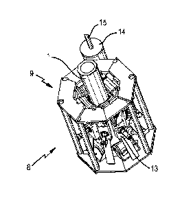
W02011/058369 pCT/0B2010/051891
23
1 13 within the inspection tool 8 for a full circumferential coverage of
the flexible riser 1, also
2 ensures that all of the ferromagnetic layers within the flexible riser 1
are magnetised
3 hornagenously. This homogenous magnetization extends to all of the
ferromagnetic
4 stripes, even those that are tilted with respected to the axial
orientation of the flexible riser
1.
6
7 To perform a full circumferential PSET test with the inspection tool 8
the sensor modules
8 13 are employed as described above. In particular, the strength of the
magnetic field
= 9 generated by the magnetiser units 18 is controlled so as to select
which particular layer of
the flexible riser 1 the eddy currents 37 are able to penetrate down into and
hence which
11 layer of the flexible riser us to be inspected at that time. This is
done by steadily
12 saturating the outer layers of the flexible riser 1 with the generated
magnetic fields until the
13 layer to be inspected is reached. Once this specific layer of the
flexible riser 1 is reached
14 the magnetic field strength can be fine adjusted so as to optimise the
detection of the eddy
current signals 37. This process can be repeated until each of the ferrous
layers of the
18 flexible riser 1 have been tested.
17
18 The inspection tool 8 is then moved along the length of the flexible
riser 1 so as to allow
19 the PSET within each of the ferrous layers to be repeated until the
whole of the flexible
riser 1 has been tested. The incorporation of the suspension wheel mechanisms
23 allow
21 for the radial position of sensor modules 13 to alter as the inspection
toot 8 moves along
22 the flexible riser 1. As a result the inspection tool 8 can negotiate
bends and changes in
23 diameter of the flexible riser 1 while allowing the sensor module 13 to
remain in contact
24 with the flexible riser 1,
26 The inspection tool 8 is designed such that it may operate under water.
In particular the
27 buoyancy of the Inspection tool 8 is such that the net weight allows for
the slow lowering of
28 the inspection tool 8 into the water. One possible deployment method is
to therefore
29 suspend the inspection tool 8 from the surface of the water on a steel
cable and allow it to
slowly descend into the water and along the length of the flexible riser 1.
The distance
31 travelled by the inspection tool 8 can then be obtained from the
rotation of a sheave wheel
32 top-side. Preferably the required energy supply and detected signals
would still be
33 handled by the umbilical 15.
34
CA 02815623 2016-08-18
W02011/058369 PCT/GB2010/051891
24
1 On completion of the test the magnetiser units 18 of the sensor modules
13 would then be
2 located in their deactivated position again so allowing the inspection
tool 8 to move to the
3 open configuration of Figure 2(b). The inspection tool 8 can therefore be
detached from
4 the flexible riser 1 and returned to the floating production platform.
6 Figure 6 shows schematically the interaction 38 of different components
of the inspection
7 tool 8. At step 39, once the Hall sensors 21 have been employed in
conjunction with the
8 magnetiser units 18 to set the required permeability within a particular
layer of the flexible
9 riser 1 the partial saturation eddy current test is performed. Test are
carried out over a
surface area of the flexible riser 1 and the measured data is combined at step
40 in the
11 Inspection control unit 16, At step 41, the data are analysed in the
inspection control unit
12 16 and are compared with calibration data held in database 42. The
results of this
13 analysis may be used to directly classify (step 43) the flexible riser
1, for example
14 indicating that it is suitable or unsuitable for a particular
application. Alternatively, the
classification step 43 may be based on a report at step 44. The report may be
written to a
16 database at step 45. in addition, at step 48, a display may be generated
from the report,
17 for display to a user. The user, who may be an expert in non-destructive
testing and non
18 destructive test data interpretation, may then classify the flexible
riser 1 based on their
19 Interpretation of the data. Alternatively, the expert user may confirm
or verify an automatic
classification performed by the inspection tool 8. The results of the
classification may be
21 stored along with the report data and details of the flexible riser 1 or
particular oil and gas
22 installation tested.
23
24 Figures 7 and 8 are flow charts which show the processing of the
measurement data
according to example embodiments of the invention. In these embodiments, the
data
26 processing module 47 is located within the inspection control unit 16
which is located
27 remotely from the sensor modules 13, and is configured to receive the
data transmitted by
28 the sensor modules 13 via a fibre optic interface 48. The fibre optic
interface 46 is
29 preferably located within the electronic bottle 14.
31 In the example of Figure 7, the measurement data are received in the
data processing
32 module 47 from the fibre optic interface 48 and multiplexer board 25. In
step Cl the partial
33 saturation eddy current measurement data are received in the data
processing module 47,
34 and the signal phase (step C1-2A) arid the signal amplitude (step C1-
213) are evaluated
individually. The analysing algorithm uses in step 01-2A the signal phase to
characterise
CA 02815623 2016-08-18
W02011/058369 PCT/GB2010/051891
a type of event which has been detected in the wall of the component 17, and
uses in step
2 CI 2B signal amplitude as a representation of the order of magnitude of a
detected event.
3 The results are indicated at evaluation step El.
4
5 This comparison with calibration data held in database 42 takes place at
step V1, and may
6 be used directly to provide an assessment of the condition of the
flexible riser 1. The
7 result of the comparison is recorded in data storage means at step DI.
8
9 An alternative processing method is shown schematically In Figure 8 of
the drawings, and
10 is also carried out while using the sensor module 13 in data processing
module 47b. The
11 embodiment of Figure 6 is similar to that of Figure 7, with like steps
indicated with like
12 reference numerals. However, the embodiment of Figure 8 differs in that
provision is
13 made for an additional evaluation of the test component 17 by the use of
predetermined
14 quality criteria which are preset into the system as analysis
thresholds, An appropriate
15 number of analysis thresholds Si to Sn are preset In the data processing
module 47b. At
16 step H1 to Hn, the evaluation results El are compared with the analysis
thresholds. A
17 signal indication is output at step K, for example if the analysis
threshold has been
18 exceeded, and indicates that the test object should be rejected. In step
V1-Vn, a visual
19 indication is presented to an operator, and step D1 to Dn, the analysis
results are recorded
20 in the data storage module 45. In this embodiment, the results of the
evaluation steps El
21 may optionally be visually (and/or audibly) presented to the operator at
steps V1-Vn.
22
23 In the method of Figure 8, the inspection tool is calibrated before use,
by using calibrating
24 test objects. These calibrating test objects are of substantially the
same dimensions and
25 materials as the components to be inspected. The calibration test
objects comprise
26 artificially-produced Instances of damage to the material with known
dimensions. In a
27 preferred embodiment, the calibration defects are made according to
international
28 standards, such as the specifications of the American Petroleum
Institute (API). The test
29 defects may for example be produced by spark erosion, machining or
drilling. By using
calibrated test objects, the sensitivity of the tool system to the kind of
defects which are
31 typically encountered can be verified. After calibration to the API
standards, the inspection
32 tool may be used for the inspection of components, including tubular
components used in
33 the oil and gas exploration and production industries.
34
CA 02815623 2016-08-18
W02011/058369
PCT/GB2010/05189 I
26
1 In an alternative embodiment of the Inspection tool 8 there may be
incorporated, in
2 addition to, or as an alternative to the Hall sensors 21, a mechanical or
electrical sensor
3 configured to monitor the rotational position of the permanent magnet 27
e.g. a
4 potentiometer whose output varies in response to the rotational position
of the permanent
6 magnet 27. In this way the mechanical or electrical sensor may be used to
determine the
6 level of the magnetic field generated by the magnetiser units 18.
7
8 The described inspection tool provides a number of significant advantages
over the
9 apparatus and methods known in the art. in the first instance the use of
a rotatable
permanent magnet to provide the required magnetic field for the PSET removes
the
11 requirement for heavy electromagnets to be employed. This removes the
requirement to
12 supply considerable electrical power to the inspection tool. This has
obvious benefits
13 since the tool is often deployed in a remote sub-sea environment where
the supply of
14 power is restricted. Moreover, in generating the magnetic field no heat
is dissipated which
can, if not properly taken care of, destroy parts of the inspection tool.
16
17 The described Inspection tool operates by employing a magnetically
biased eddy current
18 technology which is capable of carrying out non-destructive testing
within various layers of
19 a multilayer component e.g. a flexible riser. The control of the level
of magnetisation
allows for differentiation of which of the layers the observed defects are
found located. As
21 a result defects can be detected within deeper layers even when the
layers on the top are
22 intact.
23
24 The described sensor module provides further advantages to the
Inspection tool over the
apparatus and methods known In the art, In the first instance the
incorporation of the Hall
26 sensors provides non-destructive test apparatus that Is more accurate
and flexible in its
27 modes of operation since their employment provide a means for the actual
permeability of
28 a material being tested to be measured. As a result the Hall sensors can
be used in
29 conjunction with the magnetiser units so as to ensure that the
permeability In a test
component matches that of the calibrated standard. This removes the need for
alternative
31 non-destructive testing techniques to be employed to determine or
corroborate the test
32 results obtained by the inspection tool so saving on the time and costs
incurred when
33 .employing the
described apparatus. Indeed, as described previously, there are often
34 environments where such alternative non-destructive test apparatus
cannot be deployed
CA 02815623 2016-08-18
W020111058369 PCT/GB2010/051891
27
1 and so in these circumstances determination or corroboration would simply
not be
2 available.
3
4 The Hall sensors may be employed within a feedback loop to the magnetiser
units so
6 allowing for the Magnetic field hne density within a lest component to be
maintained even
6 when the distance between the sensor module and the test component is
altered e.g. by
7 variations in diameters of, or the presence of bends in the test
component. This provides
8 for more accurate and reproducible results on the test components, even
when they
9 exhibit a variety of physical dimensions, when compared with results
obtained from non-
destructive test apparatus known in the art.
11
12 The described inspection tool also offers greater flexibility in its
modes of operation when
13 compared with other apparatus known in the art. For example the
Incorporation of the Hall
14 sensors provides a means for reducing the occurrence of false readings
when the
associated sensor modules are operated within an absolute mode. Thus the
described
16 apparatus and methods can be accurately employed in both absolute and
differential
17 mode of operation. The described apparatus and methods may therefore be
readily
18 deployed for the non-destructive testing of ferromagnetic materials in
the form of single or
19 multiple layer structures e.g. pipes, plates, vessels (tank floors,
vessel plating), steel
bridge structures, flexible risers and steel wire ropes (including power
wires).
21
22 For single layer materials and/or structures, the Inspection tool can
detects and analyse
23 the severity of defects or material property changes on the material
surface, on the
24 underside of the material as well as In the complete wall. For multiple
layers materials
26 and/or structures, the Inspection tool can detect and analyse the
severity of defects or
26 material property changes in all ferromagnetic layers contained therein.
27
28 The invention provides an inspection tool for the non-destructive
testing of a test
29 component made of an electrically conductive material, and in particular
for an in situ
component such as a flexible riser. The Inspection tool has one or more sensor
modules
31 configured to locate with a surface of the test component. The sensor
modules include a
32 magnetiser unit having a movably mounted permanent magnet, which is
configured to
33 generate a variable DC magnetic field within the test component at any
fixed position
34 along the length of the test component. At least one eddy current probe
is provided and
CA 02815623 2016-08-18
W02011/058369 PCT/G82010/051891
28
1 the sensor modules are configured to perform a partial saturation eddy
current test within
2 the test component.
3
4 An inspection tool for the non-destructive testing of a test component
made of an
6 electrically conductive material is described. The inspection tool
employs movably
6 mounted permanent magnets, which provides a means for generating a
variable DC
7 magnetic field within the test component, and eddy current probes so as
to provide a
8 means for performing a partial saturation eddy current test upon the test
component. The
9 eddy current probe preferably comprises an integrated magnetic field
sensor which
increases the accuracy and flexibility of the modes of operation of the
described apparatus
11 and methods. The described apparatus and methods are particularly suited
for the
12 inspection of tubular components that are often remotely located within
the oil and gas
13 exploration and production industries.
14
The foregoing description of the invention has been presented for purposes of
illustration
18 and description and is not intended to be exhaustive or to limit the
invention to the precise
17 form disclosed. The described embodiments were chosen and described in
order to best
18 explain the principles of the invention and its practical application to
thereby enable others
19 skilled in the art to best utilise the invention in various embodiments
and with various
modifications as are suited to the particular use contemplated. Therefore,
further
21 modifications or improvements may be incorporated without departing from
the scope of
22 the invention as defined by the appended claims.
23
24