Note: Descriptions are shown in the official language in which they were submitted.
CA 02816141 2013-04-25
WO 2012/064844 PCT/US2011/059975
SINGLE LOOP MULTISTAGE FUEL PRODUCTION
FIELD OF THE INVENTION
[0011 This invention relates to a new process to directly produce
transportation fuels, such
as gasoline, jet fuel and diesel from synthesis gas containing principally
carbon monoxide,
carbon dioxide, and hydrogen.
BACKGROUND OF THE INVENTION
[0021 The prior art describes several alternatives to produce gasoline and
distillate from
synthesis gas that do not anticipate the present invention of four reaction
stages with an overall
recycle loop to produce commercial quality fuels. Chang et al (US 3,894,102)
and Zahner et al
(US 4,011,275) propose that synthesis gas be passed over methanol producing
catalyst with an
acid component activity to convert methanol to dimethylether and then feeding
this intermediate
mixed product to a fuel producing stage with recycle of light components to
mix with the
intermediate mixed product feed.
[0031 In another example, Chang et al (US 4,076,761) use synthesis gas
produced from
coal, shale and/or residua that is conveyed to a carbon oxide converter and
thence to a fuel
producing stage with recycle of light gases back to the synthesis gas stage,
the carbon oxide
conversion stage or the fuel producing stage.
[004] Garwood et al (US 4,304,951) disclose the advantage of hydrotreating
only the heavy
fraction of product from a fuel producing stage using ZSM-5 catalyst. The
hydrotreating step is
carried out using essentially pure hydrogen and isolated from the prior three
stages to produce
liquid fuel from synthesis gas.
[0051 Thereby, the referenced patents proceed with four sequential stages
with separation of
1
CA 02816141 2013-04-25
WO 2012/064844 PCT/US2011/059975
liquid intermediates and product concentration steps after the first, third
and fourth stages,
resulting in a complex and low efficiency process. In addition, due to the
production of high
melting point (-79 C) durene, the cooling condenser ahead of the separator
after the ZSM-5
stage needs a light gasoline recycle wash to keep it clean from durene
deposition.
[0061 Haldor Topsoe (J. Topp-Jorgensen, "Topsoe Integrated Gasoline
Synthesis ¨ the
TIGAS Process", in D.M. Bibby, C.D. Chang, R.W. Howe, S. Yurchak ( Eds.) ,
Methane
Conversion, 1988, Elsevier Science Publishers, B.V., Amsterdam, 293-305)
simplified the Mobil
Methanol-to-gasoline (MTG) scheme by combining the first three stages within
one synthesis
gas recycle loop without intermediate separation utilizing a proprietary
catalyst for the first step
to enable it to operate effectively at the lower pressures required by the ZSM-
5 step. Methanol
production is equilibrium limited and conversion would be enhanced by
operation at high
pressure. However, at high pressures, ZSM-5 produces increasing amounts of the
undesirable
component, durene. The proprietary catalyst produced DME in addition to
methanol to increase
the conversion to oxygenates. At elevated pressure, however, ZSM-5 produces a
gasoline with a
very high heavy aromatic content, in particular with high concentrations of
durene that then
would require hydrotreating as in the MTG New Zealand plant. Operating at
about 20
atmospheres, the durene level was more than about three times a satisfactory
level and it was
stated, though not shown, that an isomerization step could be introduced into
the loop to bring
the durene content close to equilibrium, which would give a satisfactory
product (Figure 9 of the
article). The article does not show that it was demonstrated. The olefinic
content of the product
was reduced as the pressure of hydrogen was increased and was overall lower
than in the Mobil
MTG product thereby producing lowered Research and Motor Octanes.
[007] In Skov et al (US 4, 520,216), three stages are sequenced with no
intermediate
2
CA 02816141 2013-04-25
WO 2012/064844 PCT/US2011/059975
separation using a single recycle loop with interstage heat exchange. This
scheme produces an
undesirable high durene content fuel. Jorn et al (US 4,481,305) proposes a
very complex set of
recycles for a three-reaction stage configuration.
[0081 In still another configuration, catalytic activities of the first
three stages were
integrated into one catalyst for a one stage process (F. Simard , U.A. Sedran,
J. Sepulveda, N.S.
Figoli, H.I. de Lasa, Applied Catalysis A: General 125 (1995):81-98). The one-
stage conversion
process used a combined synthesis gas/methanol and methanol-to-gasoline
catalyst, a ZnO-Cr203
+ ZSM-5 catalyst, that produced gasoline compounds from synthesis gas feed,
however, the
selectivity to carbon dioxide was extremely high, ca 70 %, making the process
impractical. The
overall reaction is described by 2nC0 + nH2 (CH2)11 + nCO2 with a minor amount
of water
(Javier Erena et al, Chemical Engineering Science 55 (2000) 1845-1855).
[0091 The complexity of the demonstrated and commercialized fixed bed Mobil
Methanol-
to-Gasoline (MTG) process can be appreciated from the description of the
commercialized MTG
process by Yurchak in D.M. Bibby, C.D. Chang, R.W. Howe, S. Yurchak (Eds.),
Methane
Conversion, 1988, Elsevier Science Publishers, B.V., Amsterdam, 251-272. In
this process,
synthesis gas is first converted to a methanol/water (CH3OH/H20) mixture in a
stand-alone plant.
The methanol/water mixture is recovered and sent to intermediate tankage.
Recycle is used to
provide a heat sink for the highly exothermic reaction and to enhance
synthesis gas conversion
for this equilibrium limited reaction. The recycle gases are cooled to remove
the methanol/water
produced and must be reheated before returning to the reactor. The product
methanol/water
mixture from tankage is fed to a two stage reactor system containing a lead
reactor with a
catalyst that partially converts the methanol to dimethylether (DME) and then
to another reactor
with a recycle loop, the methanol-to-gasoline (MTG) reactor that converts the
methanol/DME
3
CA 02816141 2013-04-25
WO 2012/064844 PCT/US2011/059975
mixture to a heavy gasoline containing large amounts of durene, 1,2,4,5-
tetramethyl benzene
molecule that has a high freezing point (79.3 C) and must be removed to make a
viable gasoline
product. The removal is effected by a hydrotreating step performed on a heavy
fraction of the
intermediate product from the fuel producing reactor stage and the
hydrotreated fraction is
combined with the light gasoline fraction to produce the gasoline product. The
hydrotreater is
operated at elevated pressure and is supplied with a hydrogen rich stream,
which is produced
from a portion of the synthesis gas by a separation step such as Pressure
Swing Adsorption
(PSA). The hydrotreating catalyst is presulfided and operated with a hydrogen
rich gas recycle
(Yurchak, 1985) and Garwood et al, (US Patent 4,304,951). One of the catalysts
tested but
rejected due to low activity is a presulfided commercial cobalt molybdate on
alumina (CoMo0õ/
A1203) catalyst.
[00101 The commercial plant built and operated in New Zealand using this
scheme has the
complexity of three recycle catalyst loops and three separation steps
involving cooling the
intermediate products to liquefy them to enable conventional separation and
distillation steps and
stepping down of pressures and recompression, one for making methanol one for
making the raw
gasoline and the third for removing the durene. Typical catalysts and
conditions used in each
step in the Mobil MTG plant built in New Zealand are shown in Table 5 below.
It is clear from
this abbreviated description that this prior art process is quite complex and
inefficient in its
handling of intermediate products and the recycles and it requires several
high cost high pressure
feed and recycle compressors, and high pressure pumps.
4
CA 02816141 2013-04-25
WO 2012/064844
PCT/US2011/059975
Table 5(a). Prior Art MTG Reaction Sequence
Principal Reactions Feed
Catalysts Typical Reactor Typical Reactor
Temperature, C Pressure, Atm
Note (1) Note
(2)
CO + H2 4=>CH3OH H20 CO, H2 Reduced 230 - 290
50 ¨ 100
CuO/ZnO/
A1203
CH3OH <=> (CH3)20 + H20 CH3OH, H20 y-A1203 310 - 320 18 -
22 pressure
CH3OH = (CH2)11 +n H20 CH3OH, (CH3)20, ZSM-5 350 - 366 18 -
22
n/2(CH3)20 = (CH2)11 + ni2H20 H20
Durene <=>iso-Durene (CH2)11 , H2 Sulfided Ni- 220 -
270 30 - 40
W on
Si02/A1203
/faujasite
Notes (1): (CH2)11 with 4 < n < 10 denotes on the average
the composition of the gasoline product which is a mixture of
paraffins, iso-paraffins, olefins, cyclics and methyl substituted
aromatics.
Note (2) Reactor conditions from K.G. Allum and A.R.
Williams, "Operation of the World's First Gas-to-Gasoline Plant",
in D.M. Bibby,et al (Editors), Methane Conversion, 1988, Elsevier
Science Publishers, B.V., Amsterdam, p691-711.
[00111 In the Mobil MTG process, durene is produced in enough quantities to
result in
undesirable cold temperature performance of the gasoline and must consequently
be reduced. It
is shown in Sergei et al. ("Process Aging Studies in the Conversion of
Methanol to Gasoline in a
Fixed Bed Reactor", Ind. Eng. Chem. Process Des. Dev., Vol. 18, No. 3, 1979)
that ZSM-5
produces durene in much larger quantities than expected from equilibrium. This
is shown in
CA 02816141 2013-04-25
WO 2012/064844 PCT/US2011/059975
Table 5(b), which is an abstract of Table V of the reference.
Table 5(b)
time on stream in cycle, h 11 645
maximum temperature, F 745 745 779 779
tetramethylbenzenes, mol % equil exptl equil exptl
durene (1,2,4,5-) 33.0 67.6 32.8 97.3
isodurene (1,2,3,5-) 50.4 24.0 50.3 1.1
prehnitine (1,2,3,4-) 16.6 8.4 16.9 1.6
[00121 Halving the amount of durene during an average cycle has been shown
to produce a
satisfactory fuel, therefore isomerizing the tetra-methyl-benzenes to an
equilibrium mixture
would be satisfactory to eliminate part of the problem. However, a certain
amount of
dealkylation of tetra-methyl-benzene is also provided by the catalyst used in
the New Zealand
plant (Garwood et al.).
[0013] Therefore, there remains a need for an efficient process to produce
fuel from
synthesis gas, whereby the fuel contains low amounts of durene and highly
substituted benzenes
for better viscometric properties in cold temperature performance.
SUMMARY OF THE INVENTION
[00141 This invention relates to a new process to directly produce
transportation fuels, such
as gasoline, jet fuel and diesel from synthesis gas containing principally
carbon monoxide,
carbon dioxide, and hydrogen. The synthesis gas may be produced from such raw
materials as
natural gas, coal, wood and other biological materials. The process entails
four sequential
catalytic stages with intermediate heat exchange to provide the requisite
temperature in each
6
CA 02816141 2013-04-25
WO 2012/064844 PCT/US2011/059975
stage, but with no interstage separation. The unreacted gases from the fourth
stage are recycled
to the first stage. The recycle enhances the conversion of the synthesis gas
to the desired
products and also serves as a heat sink for the highly exothermic reactions
involved in each
stage. This invention is distinct from the prior art in that it operates at
elevated pressure,
preferably about 50 ¨ 100 atmospheres in all four stages, to yield high
reactor utilization
efficiencies to produces a hydrocarbon mixture ready for market as
transportation fuels after the
usual additives used in the industry are added. To the contrary, the prior art
teaches that low
pressures of 1 to 20 atmospheres in the third stage are required to produce
acceptable
transportation fuels.
[00151 This invention also provides a unique multistage process operating
at essentially
uniform pressure that converts synthesis gas to hydrocarbon fuels.
Furthermore, the multistage
process uses a single recycle loop connecting the last to the first stage.
Cooling is preferably
accomplished within and/or in-between stages to remove the exothermic heat of
reaction
produced in all stages.
[00161 The process contains four reactor stages in series, preferably
interconnected with heat
exchangers to adjust the temperature of the outflow of one stage to correspond
to the desired
inlet temperature of the next stage. Each stage may have one or more reactors
in series or in
parallel, loaded with the same catalyst. No separation or removal of
intermediate product is
made. The first stage converts synthesis gas to methanol and water; the second
stage converts a
portion of the methanol to dimethylether; the third stage converts methanol
and dimethylether to
gasoline and heavy gasoline; and the fourth stage converts the heavy gasoline
via hydrotreating
reactions to gasoline (C4 to C8), jet fuel, diesel or a combination thereof,
as desired.
[00171 An additional uniqueness of this scheme is that the requisite
hydrotreating reactions
7
CA 02816141 2013-04-25
WO 2012/064844 PCT/US2011/059975
in the fourth stage are carried out in the presence of high concentrations of
carbon monoxide,
which are present in the recycle synthesis gas and is, in effect, used as the
treat gas. We have
discovered that there are a large variety of catalysts that may be used in the
fourth stage to
achieve the requisite reactions under these unique and unusual conditions of
high partial pressure
of carbon monoxide (carbon monoxide molar fraction in the fourth stage is
about 20-25%). It is
commonly taught in the art that the hydrotreating step should be carried out
in the absence of
substantial amounts of carbon monoxide to avoid poisoning of the catalyst.
[00181 The total flow exiting from the fourth stage is cooled to condense
the product liquid
hydrocarbon and water. These are removed from the recycle gases in a high
pressure separator.
The vapor from the high-pressure separator is split into two streams: a stream
that is sent to fuel
gas and LPG recovery and another larger stream that is sent to the recycle
compressor for return
to the feed of the first reaction stage. The recycle gas is composed of
unreacted synthesis gas
and small amounts of by-product light gases. The overall process yield is
greater than about
25%, preferably about 15 to about 45% (based on weight of the converted
synthesis gas). The
fuel produced from the process preferably contains about 30 to about 40 %
straight and/or
branched paraffins, more preferably C4 to C8, most preferably C5 to C7; about
15 to about 25%
cyclic paraffins, preferably C6 to C8 hydrocarbons; about 2 to about 5%
toluene; about 6 to
about 10 % xylenes; about 10 to about 15% trimethylbenzenes (TMB), and about
15 to about
20% durene and other tetra- or higher methyl-substituted benzenes.
[00191 The entire reactor system is operated at elevated pressure, 50 to100
atmospheres, with
modest pressure decreases due to pressure drop as a result of flow through the
catalysts, pipes,
and heat exchangers. This pressure drop is maintained at modest values to
economize on the size
and cost of the recycle compressor. The high pressure enhances the conversion
of synthesis gas
8
CA 02816141 2013-04-25
WO 2012/064844 PCT/US2011/059975
to the methanol intermediate in the first stage, has no effect in the
conversion of methanol to the
intermediate dimethylether. However, it is known in the art (Yurchak) that the
conversion of
ethanol/dimethylether to gasoline in the third stage also produces heavy
gasoline, principally >C8
aromatics, such as tri-methyl benzenes, tetramethyl benzenes, and durene. In
particular, highly
undesirable tetra-methyl benzene and durene are produced which have high
melting points (79 C
or greater) and limited solubility in the hydrocarbon mixture even at room
temperature. Their
viscometric behavior cannot be tolerated in an all-weather commercial fuel. In
the present
process, however, this intermediate product, containing heavy gasoline, is
converted to desirable
hydrocarbon products in the fourth stage by significantly reducing the
trimethylbenzene and
tetramethylbenzene and durene isomer groups via hydrotreating and producing
desirable fuel
compounds such as toluene, xylenes and C4 to C8 hydrobarbons, principally C5
to C7
hydrocarbons. This conversion is obtained by the proper choice of catalyst,
space velocity and
temperature of the reactor. The presence of heavy gasoline in the product
produced from the
third reaction is undesirable because it increases the freezing temperature of
the fuel which
renders the fuel unusable in old weather. The fourth reactor converts the
heavy gasoline to
toluene, xylenes, and/or C4 to C8 hydrobarbons, which lowers the freezing
point of the fuel
product. Preferably, the fuel product coming out of the fourth reactor has a
freezing point of less
than about -5 C, preferably about -15 to about -20 C, while the product coming
out of the third
reactor has a freezing point of about 30-50 C.
[00201 The fourth stage catalysts that we have found to selectively
accomplish this task are
Group IX or X metal oxide (e.g. nickel oxide) catalyst on alumina reduced in
the presence of
hydrogen and carbon monoxide in the absence of sulfur. In certain embodiments,
the catalyst
can be Group IX or X metal oxide (e.g. cobalt oxide) catalyst combined with a
Group VI metal
9
CA 02816141 2013-04-25
WO 2012/064844 PCT/US2011/059975
oxide (molybdenum oxide) catalyst on alumina reduced in the presence of
hydrogen and carbon
monoxide and in the absence of sulfur. A specific example of the catalyst
include unsulfided
cobalt molybdate on alumina or atomic nickel on alumina, the reduction, if
any, being carried out
in the presence of synthesis gas. Sulfiding the catalyst surface is not
necessary but catalytic
reduction using either a H2 flow or a mixture of H2 and CO under operating
temperature is
desirable. Temperature of the fourth stage ranges from 120 to 230 C (248 to
446 F) depending
on the catalyst used, with the preferred temperature being about 150-180 C
(302 to 356 F).
These temperatures are surprisingly lower than 232 to 427 C (450 to 800 F)
disclosed by
Garwood (US 4,304,951) for treating a 200-400 F bottoms fraction. We ascribe
this valuable
difference in temperature and the more desirable product mix to treating the
whole product from
the fuel forming step in the presence of synthesis gas instead of a bottoms
fraction with
principally hydrogen. We also ascribe this surprising result to using
unsulfided catalysts, unlike
Garwood that teaches by example that mixed oxide catalysts need to be
sulfided. Han et al. (US
4,973,784) teaches the use of zeolites for treating the durene containing
product in the presence
of substantial partial pressure of hydrogen producing undesirable benzene. Our
novel process
does not produce benzene. Still in another variation, Chester et al. (US
4,387,261) propose
treating the entire product from the fuel forming stage, but preferably a
heavy fraction thereof,
using ZSM-12, preferably impregnated with platinum, an expensive metal, at
elevated
temperatures and pressures to dealkylate durene to form xylene, toluene,
benzene and
undesirable light gases such as C2 and C3 hydrocarbon. The present process is
clearly superior in
that it does not produce light gases in the treating stage (stage 4). Still in
another example,
Dwyer et al. (US 4,347,397), showed that treating the whole or bottoms product
from the fuel
producing stage with zeolites principally isomerizes the durene to other
tetramethylbenzenes,
CA 02816141 2013-04-25
WO 2012/064844 PCT/US2011/059975
thereby, producing less desirable heavy product than the present process.
[00211 Examples of catalysts and temperature ranges that can be used for
the first three
stages are as follows: in the first stage, R-1, CuO/ZnO/ A1203 in the range of
190 to 300 C, with
the preferred range of 220 to 260 C; in the second stage, R-2, gamma-alumina
in the range of
300 to 450 C with the preferred range of 400 to 420 C ; and in the third
stage, R-3, ZSM-5 in the
range of 300 to 500 C with preferred range of 343 to 420 C.
11
CA 02816141 2013-04-25
WO 2012/064844 PCT/US2011/059975
BRIEF DESCRIPTION OF THE DRAWINGS
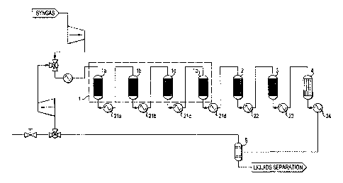
[00221 Figure 1 is a schematic of a process of the present invention.
[00231 Figure 2 is a schematic of an embodiment of the present process that
includes four
reactors in Stage 1.
[00241 Figure 3 is a schematic of an embodiment of the present invention
that introduces the
synthesis gas feed at the entrance of the third reactor (R-3).
[00251 Figure 4 is a GC-MS spectrum of a typical fuel obtained when the
Reactor Stage 4 is
not used.
[00261 Figure 5 is a GC-MS spectrum of the fuel product using the
hydrotreating reactor
(Reactor Stage 4) containing Catalyst A and Catalyst B.
[00271 Figure 6 is a comparison of fuel samples with and without Reactor
Stage 4 with
Catalyst A.
12
CA 02816141 2013-04-25
WO 2012/064844
PCT/US2011/059975
DETAILED DESCRIPTION OF THE PREFERRED EMBODIMENTS
[00281 The
invention will be readily understood from the Figures. Referring to Figure 1,
synthesis gas enters the process through conduit 19 at low pressure, and
preferably is compressed
by compressor 7 to 20 to 100 atmospheres, preferably 50 atmospheres, and is
passed to the first
reactor 1 via conduits 17 and 18. The first reactor 1 (R-1) converts synthesis
gas to principally
methanol and some water. The product from the first reactor 1, a vapor mixture
of essentially
methanol, water and unreacted synthesis gas, flows through conduit 10 to a
second reactor 2 (R-
2). The second reactor 2 converts a portion of the methanol to dimethylether.
The product from
second reactor 2, which essentially contains methanol, dimethylether, water
and unreacted
synthesis gas, flows via conduit 11 to a third reactor 3 (R-3). The third
reactor 3 converts
methanol and dimethylether to fuel product (gasoline, jet fuel and/or diesel)
and heavy gasoline.
The product from the third reactor 3 contains essentially fuel product (C4-C8
hydrocarbons,
toluene, and xylene), heavy gasoline (>C8 aromatics) and water, with minor
amounts of
unreacted methanol and dimethylether and unreacted synthesis gas. This product
flows via
conduit 12 to a fourth reactor 4 (R-4) to convert the heavy gasoline to fuel
product. The product
from the fourth reactor 4 contains essentially fuel product with low heavy
gasoline content,
water, minor amounts of unreacted methanol and dimethylether and unreacted
synthesis gas,
which pass via conduit 13 to a separator 5. The separator 5 separates the flow
13 into three
streams: (a) conduit 22 carries out essentially water with some impurities for
cleaning and reuse
to make steam for the synthesis gas generating step not shown in the diagram;
(b) conduit 20
carries out essentially fuel product that can be commercially marketed after
addition of proper
additives as required by commerce; and (c) conduit 14 carrying essentially
light gases (including
light paraffins below C4) and unreacted synthesis gas. The flow in conduit 14
is split into two
13
CA 02816141 2013-04-25
WO 2012/064844 PCT/US2011/059975
streams: (a) flow through conduit 21 directed to further processing to recover
LPG and excess
gas for use as fuel for process heating needs; and (b) flow through conduit 15
is directed to a
recycle compressor 6. The recycle compressor steps up the pressure of the
recycle gas from
losses through flow from conduit 18 to conduit 15 to match the inlet pressure
of R-1 so that it
can be mixed with the synthesis gas feed stream from conduit 17. The flow in
conduits 15 and
16 is the greater part of the flow from conduit 14, being about 5 to 20 times
larger than the flow
in conduit 17, preferably 9 times larger.
[00291 Reactors 1 through 4 are preferably fixed bed reactors containing
catalysts for
effecting the desired reaction in each of the reactors. Due to the
exothermicity of the reactions
occurring in each stage, the reactors stages maybe sectioned with intermediate
heat transfer to
remove excess heat or the temperatures may be controlled via "cold-shot" side
streams of cooled
recycle gas for each stage or a combination of these two methods of
temperature control may be
used. Figures 2 and 3 show examples of these renditions, which are familiar to
those skilled in
the art. These examples do not limit the variations possible in the detailed
design of this process.
[00301 Figure 2 is a schematic of a further embodiment of the present
process where the first
reactor 1 contains four inter-cooled reactors (1a, lb, lc, and 1d) with heat
exchangers (21a, 21b,
21c, and 21d) cooling the outlets of each of the reactors (la, lb, lc, or 1d),
respectively.
Additionally, heat exchangers 22 and 23 are used to moderate the temperature
of the exit flows
of the second reactor 2 and the third reactor 3, respectively. An extra heat
exchanger 24 is
mounted between the fourth reactor 4 and the gas-liquid separator 5, to cool
the outlet from the
fourth reactor 4. The output from gas-liquid separator 5 is further divided
into two parts: (1) the
unreacted gas stream which will be fed into a control valve 40 to further
separate into the
recycled and the bleeding gas; and (2) the condensed liquid stream which can
be fed into a fuel-
14
CA 02816141 2013-04-25
WO 2012/064844 PCT/US2011/059975
water separator. Due to the difference in density between water and synfuel,
the water
accumulates at the bottom of the separator and can be drained out
periodically.
[00311 Figure 3 is a schematic of a further embodiment of the present
process wherein the
synthesis gas feed is introduced into the loop ahead of the third reactor 3 (R-
3). Synthesis gas
enters the process through conduit 19 at low pressure and is compressed by a
compressor 7 to
match the pressure of the flow passing out of the second reactor 2 (R-2) in
conduit 11. The
compressed synthesis gas in conduit 17 is mixed into the flow in conduit 11 to
produce the flow
in conduit 9 which is led into R-3. The flow in conduit 11 is the product from
the second reactor
2 (R-2), which contains essentially methanol, dimethylether, water, and
unreacted synthesis gas.
R-3 converts the synthesis gas and olefins and other hydrocarbon contaminants
in the synthesis
gas feed passing in conduit 9 to a product which is essentially fuel product
(principally C4-C8
hydrocarbons, toluene, and xylene), heavy gasoline (>C8 aromatics) and water,
with minor
amounts of unreacted methanol and dimethylether and unreacted synthesis gas.
The R-3 effluent
passes through conduit 12 to the fourth reactor 4 (R-4) which converts the
heavy gasoline to fuel
product. The effluent from R-4, which is essentially fuel product with low
durene content,
water, minor amounts of unreacted methanol and dimethylether and unreacted
synthesis gas,
passes via conduit 13 to the separator 5. The separator 5 separates the flow
13 into three
streams: (a) conduit 22 carries essentially water with some impurities for
reuse, such as to make
steam for the synthesis gas generating step not shown in the diagram; (b)
conduit 20 carries
essentially a fuel product which can be sold on the market after proper
additives are added as
required by commerce; and (c) conduit 14 carries essentially light gases and
unreacted synthesis
gas. The flow in conduit 14 is split into two streams with (a) flow through
conduit 21 directed to
further processing to recover LPG and excess gas for use as fuel for process
heating needs; and
CA 02816141 2013-04-25
WO 2012/064844 PCT/US2011/059975
(b) flow through conduit 15 directed to a recycle compressor 6. The recycle
compressor steps up
the pressure of the recycle gas from losses through flow from conduit 16 to
conduit 15 to match
the inlet pressure of R-3. The flow in conduits 15 and 16 is the greater part
of the flow from
conduit 14, being about 5 to 20 times larger than the flow in conduit 17,
preferably 9 times or
larger.
[00321 In Figure 3, the feed synthesis gas is introduced and mixed into the
recycle loop in the
line between R2 and R3 instead of in the line to R1, as shown in Figure 1. The
principal
advantage of this alternative over introducing the feed synthesis into R-1 is
obtained in the case
in which the synthesis gas contains alkane and/or olefin hydrocarbons
molecules with two or
more carbon atoms and/or larger cyclic and aromatic molecules. Although some
olefin species
may be in trace amounts, the catalysts residing in R-3 and R-4 convert the
olefins directly into
fuel product thus increasing the yield, prior to the reactions in R-1 and R-2.
An additional
advantage is that if this type of feed were to be fed into R-1, it would have
to be first purified by
a process, such as for example, extraction or steam reforming, to render the
feed devoid of
potential catalyst poisons for the R1 catalyst, such as olefins and aromatic
molecules. In effect,
in this rendition of the invention, third and fourth reactors 3 and 4 (R3 and
R4) act as purifiers of
the fresh feed synthesis gas for R-1, as it receives synthesis gas via the
recycle loop.
[00331 Without further description, it is believed that one of ordinary
skill in the art can,
using the preceding description and the following illustrative examples, make
and utilize the
compounds of the present invention and practice the claimed methods. The
following examples
are given to illustrate the present invention. It should be understood that
the invention is not to
be limited to the specific conditions or details described in the examples.
Reactor configuration and methods used for the Examples
16
CA 02816141 2013-04-25
WO 2012/064844 PCT/US2011/059975
[00341 The invention can be best described by giving examples from
laboratory tests of the
concept. A once-through pilot plant utilizing three "Berty-design" (Berty)
internally recycled
autoclave reactors were used in series for R-1 (the first reactor), R-2 (the
second reactor), and R-
3 (the third reactor) followed by an upflow 1.5 "x 12" long fixed bed reactor
for R-4 (the fourth
reactor). Each of these reactors simulates a reaction stage and it is clear to
those familiar with
the art that this process concept extends to the use of fixed bed reactors
instead of one or more of
the internally recycled reactors. The catalysts in the Berty reactors were
loaded into a catalyst
basket and the temperature of the bed was measured by a thermocouple inserted
into the catalyst
in each basket. The catalyst in R-4 was loaded in two layers separated by a
metal screen support
and alumina beads. The temperature was measured between the two beds. A by-
pass system
around R-4 permitted introducing or removing R-4 from the flow from R-3 to the
product
separator to demonstrate the beneficial effects of the fourth reaction stage.
The tubing
connections between reactors were heated with heating tape to prevent
condensation of liquid
intermediate and final products. The synthesis gas feed was supplied to R-1 as
a mixture of CO,
H2 and an Ar tracer supplied in pressurized cylinders, metered using mass flow
meters to give
the desired composition. The pressure of the system was held constant by a
backpressure
regulator. The depressured gas was cooled by a water cooled condenser and a
Jorgensen glass
tube was used as a separator to separate the product liquid hydrocarbon, water
and the synthesis
gas containing light hydrocarbon gases not collected in the separator. The
collected hydrocarbon
liquid was analyzed by IR and GC-MS and the total hot gases after each reactor
were sampled
and analyzed using a GC-MS. Material balance was achieved by using the Ar
tracer and a
massflow meter. The density of the collected liquid hydrocarbon was measured.
The
temperature inside each reactor was controlled via outer heater elements to
temperatures set and
17
CA 02816141 2013-04-25
WO 2012/064844 PCT/US2011/059975
measured in the inside of the catalyst beds.
[00351 A micro syringe with a fixed volume of 1 pi was used to inject the
liquid fuel into the
GC-MS system (HP7890). The reproducibility of the syringe is reasonably
accurate and the
volume fluctuation cannot exceed an uncertainty of more than 10 %. Therefore,
if a significant
variation is observed for a specific species in the mass count from the GC-MS
signal, the
sampling fluctuation caused by the syringe sampling cannot account for such
signal change. The
signal variation must then come from compositional differences between the
samples. Thus
traces and quantitative mass counts or abundance of quadrupole detection can
be used to
compare process performance.
[00361 Being that the pilot plant was once-through and contained no
recycle, the synthesis
gas flow was set to represent the recycle case by restricting the conversion
in R-1 to that
calculated for a recycle case. Thus, for a once-through case of 10% conversion
of synthesis gas
to methanol in R-1, the once-through system would be simulating a 10:1 recycle
rate for 100%
conversion.
Example 1
[00371 In this example, R-1, R-2 and R-3 were used in-line with R-4 off-
line to provide a
base case for comparison to the beneficial effect of R-4 hydrotreating. R-1
contained 400 g of
copper/zinc oxide/alumina (Katalco 51-9) catalyst, R-2 contained 200 g of
gamma-alumina (SAS
250) and R-3 contained 200 g of the zeolite ZSM-5. The synthesis gas was
composed of the
following flows: 6130 scm3 H2, 2200 scm3 CO, and 500 scm3 Ar. Temperatures
were as follows:
R-1, 280 C; R-2, 385 C; and R-3, 410 C. The pressure was 50 atmospheres at the
outlet with
minor pressure drop through the reactors. Liquid was collected in the
separator at the rate of 6-7
g/h hydrocarbon together with by-product water. The hydrocarbon was analyzed
by IR and GC-
18
CA 02816141 2013-04-25
WO 2012/064844 PCT/US2011/059975
MS. The IR was used to confirm the identity of the components in the sample.
The GC-MS
results are shown in Figure 4.
Example 2
[00381 In this example, R-1, R-2, R-3 line up, flows, temperatures and
pressure were the
same as in Example 1 and R-4 was added containing 50 g of catalyst-A
(Criterion KL6515, a 60
% Ni on alumina catalyst) held at 130 C. Liquid was collected in the separator
at the rate of 7.04
g/h hydrocarbon and by-product water. The hydrocarbon was analyzed by IR and
GC-MS. The
GC-MS results in Figure 5 (a) show that the durene content was significantly
reduced compared
to Example 1, which did not utilize R-4.
Example 3
[00391 In this example the reactor line-up and pressure were the same as in
Example 2,
however, the catalyst in R-4 was 50 g of catalyst-B (Alfa Aesar 45579, a
cobalt molybdate on
alumina) held at 140 C. Liquid was collected in the separator at the rate of
7.24 g/h hydrocarbon
and by-product water. The hydrocarbon was analyzed by IR and GC-MS. The GC-MS
results in
Figure 5(b) show that the durene content was significantly reduced compared to
Example 1,
which did not utilize R-4.
Example 4
[00401 In this example, the GC-MS traces from Example 1 and Example 3 are
superimposed
for comparison and shown in Figure 6 and quantified in Table 1. Table 1 lists
the data of
integrated area of all major bands for the liquid fuel samples with and
without R-4. The catalyst
used in R-4 is either cat-A (CRI-Critetrion KL6515) or cat-B (Alfa Aesar
45579). The retention
times of individual band (in minutes) and the percentage changes derived from
differences in
19
CA 02816141 2013-04-25
WO 2012/064844 PCT/US2011/059975
band areas are also listed in Table 1 for comparison.
[00411 It is
interesting to note that all but the n-C7 aliphatic portions, including C4,
C5, C6
and i-C7, significantly increased for the fuels after R-4 hydrotreatment. All
changes are
significant, much more than 100 % of the original values. Also,
dimethylcyclopentane,
Table'
I
sfy.,.i,,s Retirrition timo Rand a
roa of (ho bo,,e eonci ari.N.; of the fur!' :i%ing R4 with Bond aiTa c3i
tN: i tad usint; R4 viith
troinrite.,) fop! withoot R4 (m1(F1 Psi; (x10')
f'1t.chmtge from bask.) CPI tY,10.1 Nts.hange from haw)
----------------------------------------------------- .. -----------------
i- C4 5.64 0.66 -32.21 t +233 '.',.) 26.4C (4-173'1;',)
C4 6.28 7.04 13.91 t+23(.1'1,.) 19.86 (+182
_____ _õ, ____ -4--- ----
i
i-C.5 8.91 107.04 264.96 (+147 ';0 201.05 (+87.8
C5 9.25 MSS 60..17 (+118 %)
J 4512 ___ t+.106.2.)
_. _______________________________________________________________________ i
i-C6 10.83+ 10,91 261.82 561.69 i+114'+':
`108-b]=,.56.1 %)
i
C6 11.15 /9.95 S3.R1 (+110 %) 39.54 t +98,2
Dirmetiwi = 12.16 19,74 41.54 (+11V4?) 21,67 t +9.8
<1,:.)
cyclo,CS
-C.7 12.41 101.96. 232.91 (1,128 '.:.:".) 165,63 (+62.6 ':))
CJ' 12. ..1,' 19,.1 1,31.13 (-24 ''.'A1 1 i.12
.-i2.-7%
,
Dimethyh 13.53 41'1.13 89.48 tA436 %) 70.52
(+46.5 %)
r.Niclo-C.6
--------------- + -------------------------------------------------------- 4
Toloents 15.22 60.6e 48,62 f,-.19,C
%) 5139 t- 12 =-.,:.1
--------------- 4- ------------------------------------------------------- 4
Xylmo 18.1 4- li3,9 270,5 24550 (.'1=_2'.:.'0
256.EA ( -5.1%)
TM 13 ; 23.3+ 24.1 763.55 646A7 t-15.4 t:.:,)
660,11 (-13.5 t',4
0.5.8
----i
Dui-ene 36-40 2238.10 1551.3 t- 30.1 1
1456.48 [34.9
dimethylcyclohexane, and other alkyl-substituted cyclic components increased.
On the other
hand, the areas under the curve for tri- and tetra-methylbenzene as well as
toluene and xylenes
are lower for the R-4 product, suggesting conversion from heavy aromatics to
paraffins,
naphthenes and less substituted aromatics.
CA 02816141 2013-04-25
WO 2012/064844 PCT/US2011/059975
[00421 We can simplify the data by grouping them with similar molecular
size. For example,
i-C4 and C4 can be grouped as C4 total. The grouped data are listed in Table
2. As we group the
data following molecular sizes, the increase using cat-A is 236 % for C4, 152
% for C5, 118 %
for C6 and 103 % for C7; with larger increases for the smaller molecules, but
on the basis of
smaller amounts in the feed to R-4. The increase of cyclic components is
relatively lower. For
example, the increase for dimethylcyclohexane is 86 % for cat-A and 46.5 % for
cat-B. All the
substituted aromatics decreased across R-4 and most significantly because of
their larger amount,
trimethylbenzene and durene.
Table 2
Spec ie :33pd õIf of ts..Beiiu
tiiel u>ir g R4 with Band aiN of the !;.1=1;AirT,F;4wEih
1i4 AA !x10'.! r.4 oxge from 5,n.e) ;x1i)'
(0.4 haniv? !con, bikwi
51).32 i236 46 25 ;4177
12.8,92 325)3 (,152 "A) 246.17 1+90.9
281.77 651.5 ::+1113 448.15 +5'1,
Diriethyi-cydo-CS 19.7A 4i.54 ::+111)%:q 2157 1+9,8 '!.4
121.,15 241.69 ;#103 178.;,1 1+417.3
CC7:.15
Dimethyl-cycio-C6 48.13 86 3.=.1 70.52 i+4F.6
lolue -12
niene 211Q.5 245.5Q ;-9..2 v..5? 251i113 1 5.1
IMB ?63,55 -15_,3%) 66(1.11 (43.5
Durene 2238.711 1551.3 I456.48
[00431 The beneficial effect of the hydrotreatment is evident in that all
desirable fuel
components increased at the expense of significant decreases of the
undesirable
trimethylbenzenes and durene.
Example 5
21
CA 02816141 2013-04-25
WO 2012/064844 PCT/US2011/059975
[00441 Further test were carried out at various R-4 temperatures and we
found surprisingly
that an optimum temperatures for R-4 exist to produce the highest rate of
hydrocarbons. These
results are shown in Table 3. It is clear that Catalyst-B exhibits a maximum
fuel production rate
at about 140 C, whereas Catalyst-A would appear to have an optimal temperature
of about
130 C. The measurements suggest that the beneficial reactions that reduce the
trimethyl- and
tetramethybenzene including durene require a certain minimum temperature but
as the
temperature is further increased cracking reactions reduce the fuel yield.
Table 3
Catalyst R-4 Temperature, Liquid Fuel
C Collected, g/h
Catalyst - A 130 7.04
170 6.11
190 5.39
220 5.15
Catalyst ¨ B 120 6.03
140 7.24
160 5.83
180 4.83
Example 6
[00451 The product from R-4 has significantly improved in viscometric
properties over that
obtained from R-3. The freezing point of the fuel was decreased and the
viscosity was
decreased. The fuel color is also changed from yellow to colorless. However
the density of the
fuel was not significantly changed indicating that the aromatic content was
not changed
significantly. The fuel density at room temperature from R-3 was 0.83 g/ml and
from R-4, 0.82
g/ml.
Example 7
22
CA 02816141 2013-04-25
WO 2012/064844 PCT/US2011/059975
[00461 This example compares the fuel product rate with and without R-4 as
given in
Examples 1, without R-4 and Example 5 with R-4. Table 4 below shows the
comparison:
Table 4
R-4 Temperature, Fuel Rate, g/h
C
Without R-4 5 - 6
With R-4 Catalyst-A 130 7.0
With R-4 Catalyst-B 140 7.2
The comparison shows that, by producing a more advantageous mix of
hydrocarbons, R-4
enhanced the recovery of fuel.
[00471 Although certain presently preferred embodiments of the invention
have been
specifically described herein, it will be apparent to those skilled in the art
to which the invention
pertains that variations and modifications of the various embodiments shown
and described
herein may be made without departing from the spirit and scope of the
invention. Accordingly, it
is intended that the invention be limited only to the extent required by the
appended claims and
the applicable rules of law.
23