Note: Descriptions are shown in the official language in which they were submitted.
CA 02816699
WO 2012/084719
PCT/EP2011/073076
- 1 -
FOLDING UNIT FOR FORMING SEALED PACKAGES OF POURABLE
FOOD PRODUCTS
TECHNICAL FIELD
The present invention relates to a folding unit for
forming sealed packages of pourable food product.
BACKGROUND ART
As is known, many liquid or pourable food products,
such as fruit juice, UHT (ultra-high-temperature
treated) milk, wine, tomato sauce, etc., are sold in
packages made of sterilized packaging material.
A typical example is the parallelepiped-shaped
package for liquid or pourable food products known as
Tetra Brik Aseptic (registered trademark), which is made
by creasing and sealing laminated strip packaging
material. The packaging material has a multilayer
structure comprising a base layer, e.g. of paper,
covered on both sides with layers of heat-seal plastic
material, e.g. polyethylene. In the case of aseptic
packages for long-storage products, such as UHT milk,
the packaging material also comprises a layer of oxygen-
barrier material, e.g. an aluminium foil, which is
superimposed on a layer of heat-seal plastic material,
and is in turn covered with another layer of heat-seal
plastic material forming the inner face of the package
eventually contacting the food product.
CA 02816699
WO 2012/084719
PCT/EP2011/073076
- 2 -
Packages of this sort are normally produced on
fully automatic packaging machines, on which a
continuous tube is formed from the web-fed packaging
material; the web of packaging material is sterilized on
the packaging machine, e.g. by applying a chemical
sterilizing agent, such as a hydrogen peroxide solution,
which, once sterilization is completed, is removed from
the surfaces of the packaging material, e.g. evaporated
by heating; the web so sterilized is then maintained in
a closed, sterile environment, and is folded and sealed
longitudinally to form a tube, which is fed vertically.
In order to complete the forming operations, the
tube is filled with the sterilized or sterile-processed
food product, and is sealed and subsequently cut along
equally spaced cross sections.
More precisely, the tube is sealed longitudinally
and transversally to its own axis.
Pillow packs are so obtained, which have a
longitudinal seal and a pair of top and bottom
transversal seals.
Alternatively, the packaging material may be cut
into blanks, which are formed into packages on forming
spindles, and the packages are then filled with the food
product and sealed. One example of this type of package
is the so-called "gable-top" package known by the trade
name Tetra Rex (registered trademark).
CA 02816699
WO 2012/084719
PCT/EP2011/073076
- 3 -
More specifically, the pillow packs comprise a
parallelepiped-shaped main portion; and opposite,
respectively top and bottom, end portions tapering from
the main portion to respective sealing lines crosswise
to the pack. Each end portion has substantially
triangular flaps projecting from opposite sides of the
main portion; and a low rectangular tab projecting from
the relative sealing line.
Packaging machines of the above type are known, on
which the pillow packs are turned into folded packages
by automatic folding units.
Folding units are known, for example from the
International Application No W02008122623 in the name of
the same Applicant, which substantially comprise:
- a rotary conveyor which receives pillow packs to
be folded at inlet station, conveys pillow packs to be
folded along an arc-shaped folding path, and outputs
folded packages at an output station;
- a first folding unit which interacts with a
bottom portion of the pack travelling along the folding
path to perform a folding operation onto the packs;
- a heating device for heating the flaps of the
packs travelling along the folding path; and
- a second folding device for pressing flaps of
each pack travelling along forming path onto respective
wall, as flaps cool.
CA 02816699 2013-05-01
WO 2012/084719
PCT/EP2011/073076
- 4 -
In greater detail, rotary conveyor comprises a
plurality of angular-spaced conveying devices, which
grip packs at inlet station, and feeds them along a
forming path to output station.
Each conveying device comprises two flat surfaces
which face each other and cooperate, in use,
respectively with a front and a rear wall of the main
portion of the relative pack to be folded.
A need is felt within the industry for the maximum
flexibility as regards the final shape of packages
folded by the folding machine.
This is particularly so in the case of newly
conceived packages which have a front wall bulging on
the opposite side of a rear wall.
DISCLOSURE OF INVENTION
It is an object of the present invention to provide
a folding unit for producing sealed packages of pourable
food products, and designed to provide the above aim in
a straightforward, low-cost manner.
BRIEF DESCRIPTION OF THE DRAWINGS
A preferred, non-limiting embodiment of the present
invention will be described by way of example with
reference to the accompanying drawings, in which:
Figure 1 is a front view of a folding unit, for
pourable food product packaging machines, in accordance
with the present invention;
CA 02816699
WO 2012/084719
PCT/EP2011/073076
- 5 -
Figure 2 is an enlarged perspective view of a first
assembly of the folding unit of Figure 1, in a first
angular position;
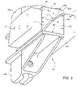
Figure 3 is a perspective view of the first
assembly of Figure 1 in a second angular position and of
a second assembly of the folding unit of Figure 1;
Figure 4 is a perspective view taken under a
different visual angle of the first assembly and second
assembly of Figure 3;
Figure 5 is an enlarged perspective view of a third
assembly of the folding unit of Figure 1; and
Figure 6 is a perspective enlarged view of a
package folded by the folding unit of Figure 1.
BEST MODE FOR CARRYING OUT THE INVENTION
Number 1 in Figure 1 indicates as a whole a folding
unit for a packaging machine for continuously producing
sealed, parallelepiped-shaped packages 2 (Figure 6) of a
pourable food product, such as pasteurized or UHT milk,
fruit juice, wine, etc., from a known tube, not shown,
of packaging material.
More specifically, the tube is formed in a known
manner upstream from folding unit 1 by longitudinally
folding and sealing a web of heat-seal sheet material,
and is filled with the sterilized or sterile-processed
food product.
The tube of packaging material is then sealed and
CA 02816699
WO 2012/084719
PCT/EP2011/073076
- 6 -
cut along equally spaced cross sections to form a number
of pillow packs 3 (Figure 5), which are then sent to
unit 1 where they are folded mechanically into
respective packages 2.
With reference to Figure 5, each pack 3 has an axis
A, and comprises a parallelepiped-shaped main portion 4;
and opposite, respectively top and bottom, end portions
6, 7 tapering from portion 4 to respective sealing lines
8, 9, crosswise to axis A, of pack 3.
More specifically, portion 4 of each pack 3 is
bounded laterally by two rectangular walls 10, that are
opposite to each other, on either side of axis A; and by
two flat concave walls 11 extending between walls 10.
In detail, a first wall 10 intended to form front
wall 102 of folded package 2 is convex and a second wall
10 intended to form rear wall 103 of folded package 2 is
flat.
Each portion 6, 7 is defined by two walls 12
substantially in the form of an isosceles trapezium,
sloping slightly towards each other with respect to a
plane perpendicular to axis A, and having minor edges
defined by respective end edges of walls 10 of portion
4, and major edges joined to each other by the
respective sealing line 8, 9.
For each portion 6, 7, each pack 3 has an
elongated, substantially rectangular tab 13, 14
CA 02816699
WO 2012/084719
PCT/EP2011/073076
- 7 -
projecting from respective sealing line 8, 9; and two
substantially triangular flaps 15, 16 projecting
laterally from opposite sides of portion 4 and defined
by end portions of relative walls 12.
With reference to Figure 6, package 2 has a top
panel of the type disclosed in the European Application
no. 10165116, which is hereby incorporated by reference.
Very briefly, package 2 comprises:
- a slanted top wall 100;
- a bottom wall 101;
- a convex front and a flat rear wall 102, 103
which extend between walls 100, 101; and
- a pair of concave lateral walls 104, 105 which
extends between walls 100, 101 and between walls 102,
103.
Furthermore, convex front wall 102 is laterally
bounded by to curved crease lines 107 which are opposite
to each other and extend between walls 100, 101.
To form a package 2, unit 1 presses portions 6, 7
of pack 3 towards each other, while at the same time
folding respective tabs 13, 14 onto portions 6, 7; folds
and seals flaps 15 of portion 6 onto relative walls 12;
and folds and seals flaps 16 of portion 7 onto
respective walls 11 of portion 4.
More specifically, flaps 15, 16 are folded with
respect to walls 12, 11 about respective fold lines 17,
CA 02816699
WO 2012/084719
PCT/EP2011/073076
-8-
18 coincident with respective edges between walls 11 and
portions 6, 7.
Unit 1 substantially comprises (Figure 1):
- a main conveyor 40 rotatable about an axis C
and which feeds a succession of packs 3 in steps along
an arc-shaped forming path B;
- a folding device 55 fitted to a fixed
structure 39 of unit 1 have an interacting surface
movable back and forth radially to axis C so as to
interact with portions 6 of packs 3 travelling along
path B to perform a folding operation on the packs;
- a heating device 60 fitted to structure 39 of
unit 1 and which heats the unfolded flaps 15, 16 of each
pack 3 travelling along path B preparatory to heat
sealing them onto respective walls 11, 12; and
- an additional folding device 65 fitted to
structure 39 of unit 1 and having a pressure device 66
and a pair of pressure devices 67 for pressing flaps 15,
16, respectively of each pack 3 travelling along path B
onto respective walls 12, 11 as flaps 15, 16 cool.
Furthermore, unit 1 also comprises a number of
pairs of rails 22 fitted to the structure 39 of unit 1.
Rails 22 of each pair extend along path B on respective
axial opposite sides of conveyor 40, and cooperate with
packs 3 along path B to perform a number of folding
operations thereon.
CA 02816699
WO 2012/084719
PCT/EP2011/073076
- 9 -
In detail, path B extends from a loading station
B1, where conveyor 40 receives each pack 3 from an input
conveyor 80, to an unloading station B2, where conveyor
40 unloads a relative package 2 (Figure 4) onto an
output conveyor 90.
From station B1 towards station B2, path B also
comprises:
- a first portion, along which a first pair of
rails 22 interact with each pack 3 to guide it along
path B; and
- a station B3 where the interacting surface of
folding device 55 interacts with each pack 3 to convert
it from a pillow configuration shown in Figure 5 to a
configuration in which portions 6, 7 are pressed towards
each other to fold walls 12 of portions 6 into a
position perpendicular to axis A and to fold walls 12 of
portion 7 into a position slanted relative to axis A;
folding device 55 further folds tabs 13, 14 onto
respective walls 12, flaps 15 about fold lines 17 into a
position parallel to axis A, and flaps 16 about fold
lines 18 into a position sloping slightly towards
portion 6 relative to the folded wall 12 of portion 7;
and
- a second portion, along which a second pair of
rails 22 interact with each pack 3 to convert it to a
configuration in which flaps 15, 16 slope forty-five
CA 02816699
WO 2012/084719
PCT/EP2011/073076
- 10 -
degrees with respect to relative walls 12, 11, and
extend from respective fold lines 17, 18 towards axis A
and away from axis A respectively.
From the second portion to station B2, path B also
comprises:
- a station B4 where heating device 60 heats flaps
15, 16 of each pack 3, preparatory to heat sealing them
onto respective walls 12, 11;
- a third portion, along which the third pair of
rails 22 fold flaps 15, 16 of each pack 3 to convert it
to a configuration, in which flaps 15, 16 slope roughly
ten degrees with respect to walls 12, 11, and extend
from fold lines 17, 18 respectively towards axis A and
away from axis A;
- a station B5 where pressure devices 66 and 67 of
folding device 65 fold respective flaps 15, 16 of each
pack 3 onto relative walls 12, 11 to complete formation
of package 2 (Figure 4); and
- a fourth portion terminating at station B2, and
along which a fourth pair of rails 22 keep flaps 16
pressed onto walls 11 to prevent accidental detachment
of the flaps as they cool.
Conveyor 80 (Figures 1) comprises an endless belt
81 looped about a not-shown drive pulley and a return
pulley 82, 83; and a number of push members 84 (only one
of which is shown in Figure 5) fitted given distances
CA 02816699
WO 2012/084719
PCT/EP2011/073076
- 11 -
apart to belt 81, and which interact with portions 6 of
respective packs 3 to move the packs from an upstream
chute 79 to conveyor 40.
More specifically, push members 84 are equally
spaced along belt 81, and travel, in use, along an
endless path of the same shape as belt 81.
On conveyor 80, each pack 3 is positioned with a
first wall 10 facing conveyor 80, with a second wall 10
facing away from conveyor 80 and with portion 6 resting
against relative push member 84.
Conveyor 80 also comprises a pair of stationary
rails 85 which are arranged at opposite lateral sides of
belt 81. Rails 85 have relative portion 86 which are
sloped relative to belt 81 and cooperate with respective
portions of tabs 13, 14 that rest on portion 86 of rail
85, so as to protect the first wall 10.
Conveyor 40 comprises a hub 41 rotating about axis
C; and a number of - in the example shown, five -
conveying devices 42 for gripping respective packs 3 at
station B1 of path B, and feeding them along path B to
station B2, so packs 3 interact with rails 22, folding
devices 55, 65, and heating device 60.
Hub 41 comprises a main body 36 and a plurality of
pairs of arms 37 which radially protrude from the outer
periphery of main body 36 (Figure 2).
More specifically, hub 41 is rotated in steps about
CA 02816699
WO 2012/084719
PCT/EP2011/073076
- 12 -
axis C by a motor not shown.
Conveying devices 42 are equally spaced angularly
about axis C; and project from hub 41, on the opposite
side to axis C and along respective radial directions
relative to axis C.
Conveying devices 42 are therefore angularly
integral with hub 41.
Each conveying device 42 comprises (Figures 2 to
4):
- a pair of supports 44a, 44b radially projecting
from respective arm 37; and
- a pair of members 45a, 45b fixed to relative
supports 44a, 44b and facing each other.
Support 44b of each conveying device 42 is hinged
to respective arm 37 about an axis D parallel to axis C.
Support 44a of each conveying device 42 is fixed to
respective arm 37.
Members 45a, 45b of each conveying device 42
comprise relative surfaces 46a, 46b which are elongated
radially with respect to axis C and face each other.
Surfaces 46a, 46b cooperate with respective first
and second walls 10 of relative pack 3, so as to hold
pack 3 along path B.
In detail, surface 46a cooperates with first wall
10 of pack 3 intended to form front wall 102 of folded
package 2 and surface 46b cooperates with second wall 10
CA 02816699
WO 2012/084719
PCT/EP2011/073076
- 13 -
of pack 3 intended to form rear wall 103 of folded
package 2.
Advantageously, surface 46a is concave.
In detail, surface 46a is bounded by a rectilinear
radial outer edge 50 and a radial inner edge 51 which
are opposite to each other, and by a pair of edges 52,
53 which are opposite to each other and extend between
edge 50, 51.
Edges 50, 51 define a theoretical plane P which is
radial to axis C and edges 52, 53 extend on the opposite
side of plane P relative to surface 46b.
In particular, edges 52, 53 extend at first at
increasing distances and then at decreasing distances
from plane P, proceeding radially to axis C from edge 50
to edge 51.
Furthermore, edges 52, 53 converge to each other
and then diverge from each other, proceeding radially to
axis C from edge 50 to edge 51, as shown in Figure 4.
Surface 46b is, in the embodiment shown, planar.
Each conveying device 42 further comprises a
slanted element 48 projecting from edge 51 of surface
46a of member 45a towards surface 46b and extending
transversally to surface 46b.
Each element 48 comprises a surface 49 which is
slanted relative to axis C and extends downwards,
proceeding from surface 46a towards surface 46b. Surface
CA 02816699
WO 2012/084719
PCT/EP2011/073076
- 14 -
49 cooperates with portion 7 of each pack 3 which is
moved along path B by relative conveying device 42.
With reference to figures 1 to 4, pressure device
66 of folding device 65 is movable back and forth along
an axis G radial to axis C between a work position, in
which it presses flaps 15 of each pack 3 onto walls 12
of portion 6 of pack 3, and a rest position, in which it
is detached from flaps 15.
Pressure devices 67 are movable back and forth
between a work position, in which relative surfaces 68
press respective flaps 16 of each pack 3 onto respective
walls 11, and a rest position, in which they are
detached from flaps 16 to permit travel of pack 3 along
path B (Figure 6).
The movement of pressure device 67 is synchronized
in a not shown manner with the movement of pressure
device 66.
When pressure devices 66, 67 are in respective work
position, each pressure device 67 extends between
surfaces 46a, 46b of the conveying device 42 which is
arranged at station B5 (Figure 3).
Surfaces 68 are advantageously convex, so as to
form concave walls 104, 105 of the finished package 2.
In detail, each surface 68 comprises a first convex
region 69 adjacent to surface 46a and a second convex
region 70 adjacent to surface 46b, when pressure devices
CA 02816699
WO 2012/084719
PCT/EP2011/073076
- 15 -
66, 67 are in respective work position.
The curvature of surface 69 is higher than the
curvature of surface 70.
Operation of unit 1 will be described with
reference to one pack 3, and as of the instant in which
a push member 84 of conveyor 80 feeds a corresponding
conveying device 42 arranged at station B1 with such a
pack 3.
More specifically, member 45b of conveying device
42 is parted slightly, by rotation about axis D, from
member 45a at station B1, to permit insertion of pack 3.
As soon as pack 3 is inserted inside relative
conveying device 42, members 45a, 45b are brought
together so that surfaces 46a, 46b rest on respective
first and second walls 10.
More specifically, pack 3 is housed inside
conveying device 42 with portion 7 facing axis C and
cooperating with surface 49 of element 48, and with
portion 6 arranged on the opposite side of axis C. In
this way, surface 49 of element 48 folds portion 7 so as
to form top wall 101 of pack 3.
Pack 3 is moved along forming path B by conveyor 40
rotating clockwise, as seen in Fig. 1, about axis C.
As conveying device 42 moves from station B1 to
folding device 55, the first pair of rails 22 cooperates
with lateral ends of tab 13 and with lateral ends of tab
CA 02816699
WO 2012/084719
PCT/EP2011/073076
- 16 -
14.
As conveying device 42 reaches station B3, folding
device 55 reaches the work position, in which it
compresses the intermediate portion of wall 12, between
flaps 15, of portion 6 towards axis C.
The above compression produces a slight translation
of pack 3 towards axis C, so that flaps 15 rotate about
respective fold lines 17 into a position parallel to
axis A, and flaps 16 rotate about respective fold lines
18 into a position sloping roughly ten degrees with
respect to the plane of top wall 100, after that folding
of package 2 has been completed.
Afterwards, folding device 55 is moved towards its
rest position.
Conveyor 40 then moves pack 3 along path B from
folding device 55 to heating device 60.
In the same time, the second pair of rails 22 folds
flaps 15, 16 towards axis A so that they, by the time
they reach heating device 60, slope roughly forty-five
degrees relative to walls 12, 11 respectively.
At station B4, conveyor 40 stops, and heating device
60 blows hot air onto flaps 15, 16 of pack 3,
preparatory to heat sealing the flaps to walls 12, 11.
Further rotation of conveyor 40 feeds pack 3 along
of path B away from heating device 60 and towards
folding device 65.
CA 02816699
WO 2012/084719
PCT/EP2011/073076
- 17 -
As conveying device 42 advances pack 3, the third
pair of rails 22 folds flaps 15 towards wall 12 of
portion 6 until it forms an angle of roughly ten degrees
with walls 12, and fold flaps 16 towards walls 11 until
flap 16 forms an angle of roughly ten degrees with
relative wall 11.
As it reaches station B5, conveyor 40 stops, and
pressure devices 66, 67 of folding device 65 are moved
into their respective work positions. In the work
position, pressure device 66 presses the heated flaps 16
onto walls 12 of pack 3, and surfaces 68 of pressure
device 67 press the heated flaps 16 onto walls 11 of
pack 3 to complete package 2.
Due to the fact that it is concave, surface 46a of
conveying device 42 controls the shape of first wall 10
with which it cooperates as packs 3 travels along path B
and, therefore, during the whole forming process of
package 2.
As a result, front wall 102 of package 2 is formed
as convex.
In the very same way, surface 46b of conveying
device 42 controls the shape of wall 10 with which it
cooperates as packs 3 travels along path B and,
therefore, during the whole forming process of package
2.
As a result, rear wall 103 of package 2 is formed
CA 02816699
WO 2012/084719
PCT/EP2011/073076
- 18 -
as flat.
Furthermore, surfaces 68 are convex and control the
shape of flaps 16 and walls 11 during the final folding
of pack 3. Therefore, walls 104, 105 of folded package 2
are formed as concave.
The pressure applied as described above seals flaps
15, 16 to walls 12, 11 so as to complete the formation
of bottom wall 101, lateral walls 104, 105 and top wall
100 of package 2.
As conveying device 42 reaches station B2, member
45b is parted slightly relative to axis D from member
45a to withdraw surfaces 46a, 46b slightly from relative
walls 10.
Folded package 2 is then released to output
conveyor 90.
The advantages of unit 1 according to the present
invention will be clear from the foregoing description.
In particular, concave surfaces 46a of conveying
devices 42 control the shape of first walls 10 with
which they cooperate as relative packs 3 are folded so
as to form corresponding packages 2. As a result, front
walls 102 of packages 2 may be formed as having a convex
shape.
Furthermore, edges 52, 53 extend on the opposite
side of plane P relative to surface 46b and control the
shape of crease lines 107, as packs 3 are folded to form
CA 02816699
WO 2012/084719
PCT/EP2011/073076
- 19 -
corresponding package 2.
Accordingly, the desired shape of crease lines 107
of packages 2 may be obtained.
Finally, convex surfaces 67 control the shape of
relative walls 11 of packs 3 with which they cooperate
as these packs 3 are folded so as to form corresponding
packages 2. As a result, lateral walls 104, 105 of
packages 2 may be formed as having a concave shape.
Clearly, changes may be made to unit 1 as described
and illustrated herein without, however, departing from
the scope defined in the accompanying Claims.
In particular, unit 1 could be used for forming
packages 2 having rear walls 103 which bulge on the
opposite side of corresponding front walls 102. In this
case, surfaces 46b of conveying devices 42 would be
concave.