Note: Descriptions are shown in the official language in which they were submitted.
CA 02817088 2013-05-31
UTILITY PATENT APPLICATION
Attorney Docket No. 201204273 (101.0655.U01)
RETAIL WALL PANEL SYSTEM
BACKGROUND OF THE INVENTION
100011 Retail businesses typically use a wide variety of systems to display
products and
related information to consumers. In order to draw attention to the products
displayed
and/or to assist the consumer in locating the particular product for which
they are searching,
additional signs or other indicating means are becoming increasingly
important. Such signs
are typically mounted to the display systems to indicate the type of product,
brand of
product, advertising, sale status indicator, department, or other information
that relates to the
displayed products and is generally helpful to the consumer. The above-
described signs are
generally positioned to correspond with particular products placed upon
shelves, pegs, or
other display devices. Preferably, such signs are securely mounted to the
shelf or display
system, are effective in communicating the indicated information such as the
product type,
brand name, logo, etc., to the consumer, and are aesthetically pleasing to
consumers so as
not to distract from the product display itself.
SUMMARY OF THE INVENTION
100021 One aspect of the present invention relates to a wall panel system for
coupling to a
retail display. The wall panel system includes a first support member, a
second support
member, a plurality of mounting brackets, a backer board, and a graphic panel.
The first
support member includes a first substantially planar panel and a first
reception cavity
extending along a top edge and a front face of the first substantially planar
panel. The
second support member is formed separately from the first support member and
includes a
second substantially planar panel and a second reception cavity extending
along a bottom
1
CA 02817088 2013-05-31
UTILITY PATENT APPLICATION
Attorney Docket No. 201204273 (101.0655.U01)
edge of a front face of the second substantially planar panel. The plurality
of mounting
brackets are configured to each be selectively coupled with the retail
display. At least a first
mounting bracket of the plurality of mounting brackets couples the first
support member to
the retail display, and at least a second mounting bracket of the plurality of
mounting
brackets couples the second support member to the retail display below the
first support
member. The backer board defines a front surface, a top edge, and a bottom
edge, the
backer board being substantially planar. The graphic panel defines a rear
surface, a top
edge, and a bottom edge. The rear surface of the graphic panel faces the front
surface of the
backer board. The top edge of the backer board and the top edge of the graphic
panel are
each slidably received in the first reception cavity of the first support
member. The bottom
edge of the backer board and the bottom edge of the graphic panel are each
slidably received
in the second reception cavity of the second support member. Other apparatus,
assemblies,
and associated methods are also disclosed.
BRIEF DESCRIPTION OF THE DRAWINGS
[0003] Embodiments of the invention will be described with respect to the
figures, in
which like reference numerals denote like elements, and in which:
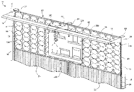
[0004] Figure 1 is a front perspective view illustration of a retail display
and a wall panel
system, according to one embodiment of the present invention.
100051 Figure 2 is an exploded, front perspective view illustration of a
portion of a wall
panel system, according to one embodiment of the present invention.
2
CA 02817088 2013-05-31
UTILITY PATENT APPLICATION
Attorney Docket No. 201204273 (101.0655.U01)
[0006] Figure 3 is a front view of a backer board of the wall panel system of
Figure 2,
according to one embodiment of the present invention.
[0007] Figure 4 is a front view of a graphic panel of the wall panel system of
Figure 2,
according to one embodiment of the present invention.
100081 Figure 5 is a rear perspective view illustration of a first support
member of the wall
panel system of Figure 2, according to one embodiment of the present
invention.
[0009] Figure 6 is a rear perspective view illustration of a second support
member of the
wall panel system of Figure 2, according to one embodiment of the present
invention.
[0010] Figure 7 is a rear perspective view illustration of a mounting bracket
that can be
used as part of the wall panel system of Figure 2, according to one embodiment
of the
present invention.
[0011] Figure 8 is partial side view illustration of the retail display and
the wall panel
system of Figure 1, according to one embodiment of the present invention.
[0012] Figure 9 is a rear perspective view illustration of a mounting bracket,
according to
one embodiment of the present invention.
[0013] Figure 10 is a front perspective view illustration of the retail
display and a wall
panel system using the mounting bracket of Figure 9, according to one
embodiment of the
present invention.
[0014] Figure 11 is a rear perspective view of a pop-off panel assembly of the
wall panel
system of Figure 1, according to one embodiment of the present invention.
3
CA 02817088 2013-05-31
UTILITY PATENT APPLICATION
Attorney Docket No. 201204273 (101.0655.U01)
[0015] Figure 12 is a rear view of an unfolded pop-off box of the pop-off
panel assembly
of Figure 11, according to one embodiment of the present invention.
[0016] Figure 13 is partial side view illustration of the retail display and
the wall panel
system of Figure 1, according to one embodiment of the present invention.
DETAILED DESCRIPTION
[0017] The present invention provides a wall panel system for use with a
retail display. In
particular, a customizable wall panel system configured to be selectively and
adjustably
coupled to the retail display. The wall panel system presents a first
substantially planar
panel and/or a second substantially planar panel each having a substantially
vertical
orientation and extending in front of walls or display fixtures of the retail
display. In one
embodiment, the first and second substantially planar panels are presented one
in front of
the other providing a three-dimensional display. Support members and
corresponding
brackets are utilized to hang the first substantially planar panel from the
retail display at a
desired position from one or more vertical supports. The resultant wall panel
system is
customizable and utilizes largely recyclable and reusable components.
[0018] Referring to the figures, Figure 1 illustrates a front perspective view
of a wall panel
system 10 and a retail display 12. Retail display 12 includes elongated
supports 14, e.g.,
substantially vertically extending supports, transversely spaced from one
another and
intervening panels or display walls 26 transversely extending substantially
vertically
therebetween. Each elongated support 14 includes a top end 16, a front surface
18, and side
surfaces 20 each extending rearwardly from opposing sides of the front surface
18. The
front surface 18 includes a linear array of reception slots 24 or engagement
features
4
CA 02817088 2013-05-31
UTILITY PATENT APPLICATION
Attorney Docket No. 201204273 (101.0655.U01)
extending, for example, in a vertical column. In one embodiment, a light
assembly 28
transversely extends outwardly in front of display walls 26 and is supported
by offset
brackets 30 extending from front surfaces 18 of elongated supports 14. More
specifically, in
the illustrated example, a laterally extending lighting housing 34 extends
from front ends 32
of offset brackets 30 and maintain lights (not shown) and facilitates
direction of illumination
from such lights toward display walls 26. In one example, each of offset
brackets is coupled
with a corresponding one of elongated supports 14 near top end 16 of the
corresponding one
of elongated slots 14 via one or more of the slots of the linear array of
reception slots 24.
100191 Architectural or wall panel system 10 is used in combination with
retail display 12,
for example, as described above and pictured in Figure 1, although use with
other retail
displays or similar structures is also contemplated and will be apparent to
those of skill in
the art upon reading the present application. Additionally referring to
Figures 2 and 3, in
one embodiment, wall panel system 10 includes a backer board 42, a graphic
panel 44, a
first support member 46, a second support member 48, and mounting brackets 50
(Figures 7
and 8). Backer board 42 and graphic panel 44 are slid into engagement with
each of first
support member 46 and second support member 48 such that backer board 42 and
the
corresponding graphic panel 44 coextend from first support member 46 to second
support
member 48. Each of first support member 46 and second support member 48
selectively
couples with one or more of mounting brackets 50, which, in turn, selectively
couple to
elongated supports 14 via the linear array of reception slots 24 as will be
further described
below. Products offered for sale and support components (not shown) are
typically placed
below wall panel system 10, e.g., products supported by support components
hung from
elongated supports 14 and/or display walls 26.
CA 02817088 2013-05-31
UTILITY PATENT APPLICATION
Attorney Docket No. 201204273 (101.0655.U01)
[0020] Wall panel system 10 is more particularly illustrated in the exploded
perspective
view of Figure 2. Backer board 42, also illustrated in Figure 3, is cut from
paper based
display board, for example, the display board known as Falconboardt graphic
display board
sold by Hexacomb Corporation of Buffalo Grove, Illinois, corrugated cardboard,
or other
suitable board providing rigidity, three dimensional stability, and structural
integrity
allowing for repeated reuse while still providing for an environmentally
responsible
disposal, e.g., substantial or complete recyclability. Backer board 42 defines
a first
substantially planar or back surface 60 and a second substantially planar or
front surface 62
opposite back surface 60. Backer board 42 further defines a top edge 64, a
bottom edge 66
opposite top edge 64, and opposite side edges 68 each extending between top
edge 64 and
bottom edge 66. In one example, each of back surface 60 and front surface 62
are the major
or primary surfaces of backer board 42 with top edge 64, bottom edge 66, and
opposite side
edges 68 each having substantially negligible dimensions in comparison.
[0021] In one embodiment, each of back surface 60 and front surface 62 is
substantially
rectangular in shape and/or at least front surface 62 is white or otherwise
coated so as not to
interfere with the visual presentation of wall panel system 10. In one
example, cutouts 70
are formed at each top corner of backer board 42 extending downwardly from top
edge 64
and inwardly from each opposing side edge 68 toward the other opposing side
edge 68.
Backer board 42 optionally additionally or alternatively includes downwardly
extending
notches 72 from top edge 64 transversely spaced from one another. Backer board
42 defines
interior apertures or interior slots 74 spaced from each of top edge 64,
bottom edge 66, and
opposing side edges 68 of backer board 42. Each of interior slots 74 is
substantially
elongated and vertically extending, and in one example, interior slots 74 are
arranged in a
multiple row array, such as the two-row array illustrated in Figure 3
including a top row 76
6
CA 02817088 2013-05-31
UTILITY PATENT APPLICATION
Attorney Docket No. 201204273 (101.0655.U01)
and a bottom row 78 of interior slots 74. The number of columns for slots in
the array of
interior slots 74 may vary, and in one embodiment, is three or more or another
suitable
number extending largely across a substantial entirety of a width of backer
board 42.
[0022] Graphic panel 44, described with reference to Figures 1, 2, and 4, is
cut from paper
or similar thin planar member configured to be readily printed, replaced, and
disposed of in
an environmentally responsible manner, e.g., substantial or complete
recyclability. Graphic
panel 44 defines a first substantially planar or back surface 90 and a second
substantially
planar or front surface 92 opposite back surface 90. Graphic panel 44 further
defines a top
edge 94, a bottom edge 96 opposite top edge 94, and opposite side edges 98
each extending
between top edge 94 and bottom edge 96. In one example, each of back surface
90 and
front surface 92 are the major or primary surfaces of graphic panel 44 with
top edge 94,
bottom edge 96, and opposite side edges 98 each having substantially
negligible dimensions
in comparison.
[0023] In one embodiment, each of back surface 90 and front surface 92 is
substantially
rectangular in shape and graphic panel 44 has a sufficient thickness to
provide an opaque
panel generally preventing see-through to features on a rear side thereof
Front surface 92 is
printed with or otherwise includes graphics 106 including textural indicia
and/or other
graphic elements desired to identify a department, product types, specific
products, prices,
sales, etc. for the retail setting where it will be used. In one example,
cutouts 100 are
formed at each top corner of graphic panel 44 extending downwardly from top
edge 94 and
inwardly from each opposing side edge 98 toward the other opposing side edge
98. Graphic
panel 44 optionally additionally or alternatively includes apertures 102
spaced just below
top edge 94 and transversely spaced from one another. Graphic panel 44 defines
interior
7
CA 02817088 2013-05-31
UTILITY PATENT APPLICATION
Attorney Docket No. 201204273 (101.0655.U01)
apertures or interior slots 104 spaced from each of top edge 94, bottom edge
96, and
opposing side edges 98. Each of interior slots 104 is substantially elongated
and vertically
extending, and in one example, interior slots 104 are arranged in a multiple
row array, such
as the two-row array illustrated in Figure 4 including a top row 108 and a
bottom row 110 of
interior slots 74. The number of columns for slots in the array of interior
slots 74 may vary,
and in one embodiment, is three or more or another suitable number extending
largely
across a substantial entirety of a width of graphic panel 44. In one
embodiment, interior
slots 104 are sized substantially identically to interior slots 74 of backer
board, are equal to
or smaller in number than interior slots 74, and/or are positioned to align
with interior slots
74 upon assembly of wall panel system 10, as will be further described below.
100241 With reference to Figures 2 and 5, in one embodiment, first support
member 46
includes a substantially planar panel 120 and a plurality of rails 122. First
support member
46 is substantially rectangular or otherwise suitably shaped to extend
longitudinally between
a first end 124 and a second end 126. Accordingly, first support member 46
defines a top
edge 128 and a bottom edge 130 opposite top edge 128, each extending between
first end
124 and second end 126, for example, substantially parallel to one another.
First support
member 46 is substantially planar, in one instance, forming a first or front
surface 132 and a
second or rear surface 134 opposite front surface 132.
100251 Each rail 122 of the plurality of rails 122 extends rearwardly from
rear surface 134
of first support member 46. More particularly, each rail 122 extends
longitudinally between
and to each of first end 124 and second end 126, in one example, and each rail
122 is
vertically spaced from other ones of the plurality of rails 122. In one
embodiment, each of
the plurality of rails 122 includes a spacing protrusion 136 extending
rearwardly from rear
8
CA 02817088 2013-05-31
UTILITY PATENT APPLICATION
Attorney Docket No. 201204273 (101.0655.U01)
surface 134 of substantially planar panel 120, for instance, substantially
perpendicularly
relative to rear surface 134. Each of the plurality of rails 122 further
includes a vertically
extending or cross member 138 extending across an end of spacing protrusion
136 opposite
rear surface 134. For example, each cross member 138 extends substantially
parallel to rear
surface 134 and one or both of upwardly and downwardly therefrom.
100261 For example, ones of the plurality of rails 122 between the topmost and
bottommost ones of the plurality of rails 122 includes a cross member 138
having a first
segment 140 extending upwardly beyond spacing protrusion 136 and a second
segment 142
extending downwardly beyond spacing protrusion 136. A topmost one of the
plurality of
rails 122 is positioned adjacent to and extends substantially coterminously
with top edge 128
of substantially planar panel 120. The topmost one of the plurality of rails
122 only includes
second segment 142 extending downwardly from spacing protrusion 136 with
substantially
no portion extending upwardly from spacing protrusion 136, in one example. A
bottommost
one of the plurality of rails 122 only includes first segment 140 extending
upwardly from
spacing protrusion 136 with substantially no portion extending downwardly from
the
corresponding spacing protrusion 136, in one example.
100271 Longitudinally extending channels 144 are defined adjacent spacing
protrusion 136
between substantially planar panel 120 and cross member 138, and each of
longitudinally
extending channels 144 is open opposite spacing protrusion 136 such that pairs
of
longitudinally extending channels 144 face toward one another. In one example,
a pair of
longitudinally extending channels 144 that face one another collectively
define a reception
track 146 for receiving a different mounting member 50, as will be further
described below.
Each reception track 146 has a substantially identical height, generally
indicated as DI in
9
CA 02817088 2013-05-31
UTILITY PATENT APPLICATION
Attorney Docket No. 201204273 (101.0655.U01)
Figure 5, such that each reception track 146 can interchangeably receive
mounting members
50 having an appropriately sized flange or similar member. In one example,
reception
tracks 146 are sized and shaped to correspond with various other sign holder
members and
brackets therefor, for example, as described in U.S. Patent Application No.
13/860,386,
entitled "Sign Holder Assembly and Associated Method," filed April 10, 2013,
which is
hereby incorporated by reference.
[0028] A spacer flange 150 extends forwardly from front surface 132 of first
support
member 46, for instance forwardly from top edge 128 of substantially planar
panel 120 a
distance substantially equal to or greater than a combined thickness of backer
board 42 and
graphic panel 44. Spacer flange 150 extends longitudinally between and to each
of first end
124 and second end 126. First support member 46 further includes a depending
or
downwardly extending flange 152 extending from an edge of spacer flange 150
opposite
substantially planar panel 120 downwardly toward bottom edge 130. In one
example,
downwardly extending spacer flange 150 extends substantially parallel to or
slightly angled
toward front surface 132 and defines a reception cavity 154 with bottom
opening thereto. In
one embodiment, one or more apertures 148 are formed through downwardly
extending
flange 150 transversely spaced from one another.
[0029] In one example, first support member 46 is formed of stacked and glued
plastic
members, as a single extruded member, or as and injection-molded plastic or
similar
member. Use of other suitable members and/or materials to form first support
member 46
are also contemplated.
[0030] With additional reference to Figure 6, in one embodiment, second
support member
48 includes a substantially planar panel 160 and a plurality of rails 162.
Second support
CA 02817088 2013-05-31
UTILITY PATENT APPLICATION
Attorney Docket No. 201204273 (101.0655.U01)
member 48 is substantially rectangular or otherwise suitably shaped to extend
longitudinally
between a first end 164 and a second end 166. Accordingly, second support
member 48
defines a top edge 168 and a bottom edge 170 opposite top edge 168, each
extending
between first end 164 and second end 166, for example, substantially parallel
to one another.
Second support member 48 is substantially planar, in one instance, forming a
first or front
surface 172 and a second or rear surface 174 opposite front surface 172.
[0031] Each of the plurality of rails 162 extends rearwardly from rear surface
174 of
second support member 48. More particularly, each rail 162 extends
longitudinally between
and to each of first end 164 and second end 166, in one example, and each rail
162 is
vertically spaced from other ones of the plurality of rails 162. In one
embodiment, each of
the plurality of rails 162 includes a spacing protrusion 176 extending
rearwardly from rear
surface 174 of support panel 160, for instance, substantially perpendicularly
relative to rear
surface 174. Each of the plurality of rails 162 further includes a vertically
extending or
cross member 178 extending across an end of spacing protrusion 176 opposite
rear surface
174. For example, each cross member 178 extends substantially parallel to rear
surface 174
and one or both of upwardly and downwardly therefrom.
[0032] For example, ones of the plurality of rails 162 between the topmost and
bottommost ones of the plurality of rails 162 includes a cross member 178
having a first
segment 180 extending upwardly beyond spacing protrusion 176 and a second
segment 182
extending downwardly beyond spacing protrusion 176. A topmost one of the
plurality of
rails 162 is positioned adjacent to and extends substantially conterminously
with top edge
168 of substantially planar panel 160. The topmost one of the plurality of
rails 162 only
includes second segment 182 extending downwardly from spacing protrusion 176
with
11
CA 02817088 2013-05-31
UTILITY PATENT APPLICATION
Attorney Docket No. 201204273 (101.0655.U01)
substantially no portion extending upwardly from spacing protrusion 176, in
one example.
A bottommost one of the plurality of rails 162 only includes first segment 180
extending
upwardly from spacing protrusion 176 with substantially no portion extending
downwardly
from the corresponding spacing protrusion 176, in one example.
100331 Longitudinally extending channels 184 are defined adjacent spacing
protrusion 176
between substantially planar panel 160 and cross member 178, and each of
longitudinally
extending channels 184 is open opposite spacing protrusion 176 such that pairs
of
longitudinally extending channels 184 face toward one another. In one example,
a pair of
longitudinally extending channels 184 that face one another collectively
define a reception
track 186 for receiving a different mounting member 50, as will be further
described below.
Each reception track 186 has a substantially identical height, generally
indicated as DI in
Figure 6, such that each reception track 186 can interchangeably receive
mounting members
50having an appropriately sized flange or similar member. In one example,
reception tracks
186 are sized and shaped to correspond with various other sign holder members
and
brackets therefor, for example, as described in U.S. Patent Application No.
13/860,386,
entitled "Sign Holder Assembly and Associated Method," filed April 10, 2013,
which is
hereby incorporated by reference.
[0034] A spacer flange 187 extends forwardly from front surface 172 of second
support
member 48, for instance, forwardly from bottom edge 170 of substantially
planar panel 160
a distance substantially equal to or greater than a combined thickness of
backer board 42 and
graphic panel 44. Spacer flange 187 extends longitudinally between and to each
of first end
164 and second end 166. Second support member 48 further includes an upwardly
extending flange 188 extending from an edge of spacer flange 187 opposite
substantially
12
CA 02817088 2013-05-31
UTILITY PATENT APPLICATION
Attorney Docket No. 201204273 (101.0655.U01)
planar panel 160 upwardly toward top edge 168. In one example, upwardly
extending
flange 188 extends substantially parallel to or slightly angled toward front
surface 172 and
defines a reception cavity 189 being open along a top edge thereof.
[0035] In one example, second support member 48 is formed of stacked and glued
plastic
members, as a single extruded member, or as and injection-molded plastic or
similar
member. Use of other suitable members and/or materials to form second support
member
48 are also contemplated.
[0036] Each of first support member 46 and second support member 48 is coupled
to
elongated supports 14 of retail display 12 (Figure 1) via one or more
connections
components or mounting brackets 50, for example two or more mounting brackets
50,
illustrated, for example, in Figure 7. In one embodiment, mounting bracket 50
is bent or
otherwise formed from a sheet of metal, such as aluminum or other suitable
metal and is
similar to the mounting brackets defined in U.S. Patent Application No.
13/860,386, entitled
"Sign Holder Assembly and Associated Method," filed April 10, 2013, which is
hereby
incorporated by reference. Mounting bracket 50 defines a front panel 190
(e.g., a backer
interface panel or connecting flange), a side panel 192 extending
substantially
perpendicularly relative to and from one end of front panel 190, and a corner
portion 194
extending between and coupling front panel 190 to side panel 192. Each of
front panel 190
and side panel 192 is substantially planar. Front panel 190 defines a top edge
196 opposite
a bottom edge 198 and extends from corner portion 194 to a free edge 200.
Likewise, side
panel 192 defines a top edge 202 opposite a bottom edge 204. In one
embodiment, top
edges 196 and 202 are positioned in a common horizontal plane while corner
portion 194 is
inset from top edges 196 and 202 toward bottom edges 198 and 204 and from
bottom edges
13
CA 02817088 2013-05-31
UTILITY PATENT APPLICATION
Attorney Docket No. 201204273 (101.0655.U01)
198 and 204 toward top edges 196 and 202 to provide clearance for front panel
190
interaction with reception tracks 146 or 186.
100371 A distance substantially equal to distance DI is defined between top
edge 196 and
bottom edge 198 of front panel 190 such that front panel 190 is sized to be
received and
selectively maintained in any one of reception tracks 146 of first support
member 46 and/or
any one of reception tracks 186 of second support member 48. Each side panel
192
additionally defines a top protrusion 206, a bottom edge notch 208, a rear
cutout 210, and/or
an internal notch 212 according to one embodiment of the invention in which
mounting
bracket 50 is configured to interact with a vertical support such as elongated
support 14
having a substantially vertical linear array of reception slots 24 (Figure 1
and 2) extending
along a front face 18 thereof. More specifically, top protrusion 206 extends
upwardly
beyond top edge 202 of side panel 192 from a rear edge 213 of side panel 192.
Rear cutout
210 extends forwardly from rear edge 213 and defines internal notch 212
extending
upwardly from a remainder of rear cutout 210 to be more forwardly positioned
than a
forwardmost portion of top protrusion 206. Bottom edge notch 208 is formed in
a vertical
alignment, e.g., along a common vertical line with internal notch 212.
100381 Additionally referring to Figure 8, during installation, one mounting
bracket 50,
according to one embodiment, is slid into each of first ends 124 and 164 and
second ends
126 and 166 of reception tracks 146 and 186 of first and second support
members 46 and 48.
The various available reception tracks 146 and 186 allow for increased
adjustability in
setting a height that wall panel system 10 will be mounted on retail display
12, as different
ones of reception tracks 146 and 186 can be selected for use to receive
associated mounting
brackets 50. Top protrusion 206 of each mounting bracket 50 is rearwardly
tilted, moved
14
CA 02817088 2013-05-31
UTILITY PATENT APPLICATION
Attorney Docket No. 201204273 (101.0655.U01)
back through a reception slot 24, and upward into an elongated support 14.
Bracket 50 is
then rearwardly and downwardly dropped or rotated such that internal notch 212
receives a
bottom edge of one of reception slots 24 and bottom edge notch 208 receives a
bottom edge
of a lower and adjacent one of reception slots 24 of elongated support 14 such
that mounting
bracket 50 is securely held in place via weight of backer board 42, graphic
panel 44, first
support member 46, and second support member 48 until intentionally moved
upwardly and
rotated to move top protrusion 206 out of the corresponding one of reception
slots 24.
[0039] In one embodiment, mounting brackets 50 are provided in each of a right
side
orientation and a left side orientation, and one mounting bracket 50 of each
orientation is
positioned in a selected reception track 146 or 186 of each of first support
member 46 and
second support member 48 at opposing ends thereof. Mounting brackets 50 are
coupled
with a corresponding elongated support 14 of retail display 12 as described
above such that
a remainder of wall panel system 10 is suspended between the two mounting
brackets 50.
Other configurations and uses are also contemplated.
[0040] Once first and second support members 46 and 48 are coupled to retail
display 12,
backer board 42 and a graphic panel 44 are provided having substantially
identical overall
dimensions such that graphic panel 44 substantially covers front surface 62 of
backer board
42, as illustrated, for example, with reference to Figures 1 and 2. In one
example, any
interior slots 104 of graphic panel 44 each align with a different one of
interior slots 74 of
backer board 42. In one embodiment, since backer board 42 is configured for
repeated use
with different graphic panels 44, backer board 42 includes interior slots 74
in standard
locations. Graphic panel 44, which is configured for single or relatively few
uses, only
includes interior slots 104 where needed to receive a pop-off assembly 250 in
a particular
CA 02817088 2013-05-31
UTILITY PATENT APPLICATION
Attorney Docket No. 201204273 (101.0655.U01)
configuration as will be further described below. As such, graphic panel 44
may have fewer
or an equal number of interior slots 74 as compared to interior slots 104
formed in backer
board 42. Graphic panel 44 has a sufficient thickness and opaqueness such that
portions of
graphic panel 44 extending over interior slots 74 in backer board 42 not
having
corresponding interior slots 104 in graphic panel 44 substantially hide
interior slots 74 from
view or detection when wall system is viewed from a front side thereof.
[0041] The backer board 42 and graphic panel 44 duo is collectively slid into
engagement
with first support member 46 and second support member 48 as shown with
additional
reference to Figure 2. More specifically, top edges 64 and 94 of backer board
42 and
graphic panel 44 are together slid into downwardly open reception cavity 154
to be
positioned therein between flange 152 and substantially planar panel 120. When
so inserted,
first support member 46 wraps around a substantial entirety of top edges 64
and 94. In one
embodiment, top notches 72 of backer board 42, top apertures 102 of graphic
panel 44, and
apertures 148 of first support member 46 align with one another and canoe
clips 156 (Figure
2) or other suitable fasteners are inserted therethrough to additionally
maintain backer board
42 and graphic panel 44 transversely in place relative to first support member
46.
[0042] Bottom edges 66 and 96 of backer board 42 and graphic panel 44 are
together slid
into upwardly open reception cavity 189 to be positioned therein between
flange 186 and
substantially planar panel 160, e.g., substantially simultaneously with
sliding top edges 64
and 94 in reception cavity 154. When so inserted, second support member 48
wraps around
a substantial entirety of bottom edges 66 and 96. As such, backer board 42 and
graphic
panel 44 are maintained between reception cavities 154 and 189 of first and
second support
members 46 and 48. When assembled, backer board 42 provides support to the
relative thin
16
CA 02817088 2013-05-31
UTILITY PATENT APPLICATION
Attorney Docket No. 201204273 (101.0655.U01)
graphic panel 44 as the two extend unsupported between first support member 46
and
second support member 48. Since backer board 42 provides such support, graphic
panels 44
can be quickly printed on a thin paper or similar material and do not require
mounting on
foam core or other independent supporting member, which reduces the time
required to
prepare such graphic panels 44 and considerably reduces costs for the one-time
use portions
of wall panel system 10. In one embodiment, each of backer board 42, graphic
panel 44,
first support member 46, and second support member 48 have a substantially
identical
overall lengths such that clean edges are formed at opposing ends of wall
panel system 10 as
illustrated in Figure 1. When wall panel system 10 is to be changed, for
example, to change
graphics 106, etc., backer board 42 and graphic panel 44 are slid out from
first and second
support members 46 and 48, graphic panel 44 is replaced with a new graphic
panel 44
having different graphics 106 and/or different interior slots 104, and the new
graphic panel
44 and the same backer board 42 are slid back into engagement with first and
second
support members 46 and 48. As such, wall panel system 10 is readily
customizable and
adjustable while providing reuse and recyclability of components. In one
embodiment, one
or more additional wall panel systems 10 are used in combination on a single
retail display
12 as shown, for example, in Figure 1.
[0043] Figure 9 illustrates an alternative or additional mounting bracket 214
for use with a
similar wall panel system 10 formed from metal or other suitable material to
define a front
panel 216 (e.g., a backer interface panel or connecting flange), a rear-
extending or side
panel 218 extending substantially perpendicularly relative to and from one end
of front
panel 216. Each of front panel 216 and side panel 218 is substantially planar,
and side panel
218 rearwardly extends from front panel 216 substantially centered on front
panel 216 in a
left-to-right or transverse direction. Front panel 216 defines a top edge 220
opposite a
17
CA 02817088 2013-05-31
UTILITY PATENT APPLICATION
Attorney Docket No. 201204273 (101.0655.U01)
bottom edge 222 spaced apart a distance DI substantially identical to distance
Di above such
that front panel 216 is sized to be received and selectively maintained in any
one of
reception tracks 146 of first support member 46 and/or any one of reception
tracks 186 of
second support member 48. Side panel 218 defines a top edge 224 opposite a
bottom edge
226. In one embodiment, top edges 220 and 224 are positioned in a common
horizontal
plane while top and bottom cutouts 228 are formed in side panel 218
immediately adjacent
front panel 216 to provide clearance for front panel 216 interaction with
reception tracks
146 or 186.
100441 Side panel 218 additionally defines a top protrusion 230, a bottom edge
notch 232,
a rear cutout 234, and/or an internal notch 236 similar to top protrusion 206,
bottom edge
notch 208, rear cutout 210, and internal notch 212 of mounting bracket 50 such
that
mounting brackets 50 and 214 interface and hang from retail display 12 in a
substantially
identical manner. However, since side panel 218 is centered relative to front
panel 216,
mounting bracket 214 is particularly well suited for use where the supported
assembly
extends across and to either side of a corresponding elongated support 14.
100451 For example, referring to Figure 10, a mounting bracket 214 (Figure 9)
is used to
support backer board 240, graphic panel 242, first support member 244, and
second support
member 246 extending across elongated support 14, but not to another elongated
support 14
such that only one bracket 214 is used in combination with each of first
support member 244
and second member 246 to hang each from retail display 12. Notably, each of
backer board
240, graphic panel 242, first support member 244, and second support member
246 is
substantially identical to a respective one of backer board 42, graphic panel
44, first support
member 46, and second support member 48 other than dimensions and/or numbers
of rails
18
CA 02817088 2013-05-31
UTILITY PATENT APPLICATION
Attorney Docket No. 201204273 (101.0655.1)01)
of first and second support members 244 and 246, etc. as will be apparent to
those of skill in
the art upon reading this application. In another embodiment (not shown),
bracket 214 can
be used between two opposing brackets 50 to support wall panel system
extending between
a first and third elongated supports and across an intermediate or second
elongated support.
[0046] In one example, wall panel system 10 additionally includes a pop-off
panel
assembly 250 as illustrated in Figure 1. Pop-off panel assembly 150 provides
an additional
surface for presenting information or graphics to consumers that is spaced in
front of front
surface 92 of graphic panel 44 to present a three-dimensional overall
appearance adding to
the aesthetic appeal and overall impact of the overall display. Additionally
referring to the
rear view of pop-off panel assembly 250 of Figure 11 and the side view
illustration of retail
display 12 and wall panel assembly 10 including pop-off panel assembly 250 of
Figure 13,
pop-off panel 250 includes a front panel 252 and a plurality of pop-of boxes
254 (e.g.,
spacing members) extending rearwardly therefrom and being configured to
selectively
couple with a remainder of wall panel system 10. Front panel 252 is formed of
a suitable
material, e.g., paper-based display board or foam core board, having
sufficient rigidity and
dimensional stability to maintain its substantial planarity between and beyond
the supporting
pop-off boxes 254. Front panel 252 defines a front surface 256 and an opposing
rear surface
258 where front surface 256 includes graphics 260 including text and/or other
indicia as
desired to enhance retail display 12.
[0047] Each pop-off box 254 is formed of a single planar piece of paperboard,
cardboard,
or other fairly rigid yet foldable material such that pop-off box 254 is
readily movable
between a flattened or storage position (see, e.g., the upper right hand pop-
off box 254 in
Figure 11) and an extended or use position (see, e.g., all other pop-off boxes
254 in Figure
19
CA 02817088 2013-05-31
UTILITY PATENT APPLICATION
Attorney Docket No. 201204273 (101.0655.U01)
11). More specifically, Figure 12 illustrates flat pop-off box 254 before
folding for use with
front panel 252. Pop-off box 254 defines a rear wall 262, opposing sidewalls
264, opposing
front flanges 266, a first intermediate flange 268, and a second intermediate
flange 270 each
separated from one another by fold lines 272. Rear wall 262 is substantially
rectangular
and is flanked on either side by one of opposing sidewalls 264 extending
outwardly away
therefrom to a corresponding one of opposing front flanges 266.
[0048] In one example, intermediate flanges 268 and 270 each extend from a top
edge of a
different one of opposing sidewalls 264 upwardly away therefrom to a free edge
274. One
of intermediate flanges 268 and 270 defines a tab 276 extending outwardly from
free edge
274 further away from the corresponding opposing sidewall 264 than free edge
274. The
other of intermediate flanges 268 and 270 defines a notch 278 corresponding in
width to tab
276 and extending downwardly toward the corresponding sidewall 264 from the
corresponding free edge 274. Intermediate flanges 268 and 270 are configured
to
selectively interlock with one another as will be further described below.
[0049] A substantially planar hook 282 is formed by one of opposing sidewalls
264, e.g.,
by extending into a portion of pop-off box 254 that would otherwise be part of
rear wall
262. Substantially planar hook 282, more particularly, is defined by cut line
280 forming
substantially planar hook 282 in a substantial L-shape extending first
transversely from the
one of the opposing sidewalls 264 beyond fold line 272 between the one of the
opposite
sidewalls 264 and front wall 262 and then downwardly as a hook extension 284
therefrom.
In one example, cut line 280 forms an aperture 286 between hook extension 284
and a
frontmost boundary of the one of opposite sidewalls 264.
CA 02817088 2013-05-31
UTILITY PATENT APPLICATION
Attorney Docket No. 201204273 (101.0655.U01)
[0050] During use, pop-off box 254 is folded along fold lines 272 such that
external
surfaces 290 of the opposing front flanges 266 are adhered or otherwise
suitably secured to
rear surface 258 of front panel 252 of pop-off panel assembly 250. In one
embodiment,
pop-off box 254 is folded during use so opposing sidewalls 264 extend
substantially
perpendicularly and rearwardly from rear surface 258 and front flanges 266 and
rear wall
262 extends substantially parallel to rear surface 258. In one example, to
maintain pop-off
box 254 in a generally rectangular shape as described above, intermediate
flanges 268 and
270 are selectively coupled with one another by sliding tab 276 into
corresponding notch
278 or via other suitable features on each of intermediate flanges 268. While
described as
extending above each of opposing sidewalls 264, in other embodiments,
intermediate
flanges 268 extends from rear wall 262 and front flanges 266 and/or below
corresponding
portions of pop-off box 254 as will be apparent to those of skill in the art
upon reading this
application.
[0051] During storage and/or transport of pop-off panel assembly 250, each pop-
off box
254 can be folded into a substantially flat position as generally illustrated
in the upper right
hand corner of Figure 11. During use of pop-off panel assembly 250, pop-off
boxes 254 are
folded outwardly and intermediate flanges 268 and 270 coupled to one another
to maintain
each pop-off box 254 with a substantially rectangular cross-sectional shape
other than planar
hook 282. The number of pop-off boxes 254 used will vary depending upon the
size of
front panel 254 and the location of pop-off boxes 254 relative to each other
is determined
such that planar hooks 282 each align with interior slots 74 and 104 of backer
board 42 and
graphics panel 44. Accordingly, during use pop-off panel assembly 250 is hung
by placing
each hook extension 284 of each planar hook 282 in an aligned one of interior
slots 74 and
104. In this manner, portions of backer board 42 and graphic panel 44 are
maintained
21
CA 02817088 2013-05-31
UTILITY PATENT APPLICATION
Attorney Docket No. 201204273 (101.0655.U01)
between hook extension 284 and rear wall 262 of each pop-off box 254 as
illustrated with
additional reference to Figure 12. In one example, distances between interior
slots 74 and
104 of a single backer board 42 and graphic panel 44 are the same as a
distance between a
last column 112 of interior slots 74 and 104 of one backer board 42 and
graphic panel pair
44 and a first column 11 of interior slots 74 and 104 of an immediately
adjacent backer
board 42 and graphic panel pair 44 as shown in Figure 1 such that pop-off
panel assembly
250 straddles between the two assemblies, but could similarly be used on a
single assembly
(i.e., a single backer board 42 and graphic panel 44 pair) as will be apparent
to those of skill
in the art.
100521 The wall panel system 10 as described above and as will be apparent to
those of
skill in the art upon reading this application provides a customizable,
readily removable and
replaceable, and environmentally conscious system that provides for increased
aesthetics
and overall clean appearance of a retail display 12 while, in some instances,
additionally
providing potential consumers with information related to the retail store
and/or products
being offered for sale therein.
100531 Although the invention has been described with respect to particular
embodiments,
such embodiments are meant for the purposes of illustrating examples only and
should not
be considered to limit the invention or the application and uses of the
invention. Various
alternatives, modifications, and changes will be apparent to those of ordinary
skill in the art
upon reading this application. Furthermore, there is no intention to be bound
by any theory
presented in the preceding background of the invention or the above detailed
description.
22