Note: Descriptions are shown in the official language in which they were submitted.
CA 02817266 2013-05-08
WO 2012/065754
PCT/EP2011/005829
AN ELECTRICALLY HEATED SMOKING SYSTEM COMPRISING
AT LEAST TWO UNITS
The present invention relates to an electrically heated smoking system having
a unit for
receiving a smoking article, wherein the unit includes a secondary power
supply and the unit is
connectable to a primary power supply.
A number of prior art documents disclose electrically operated smoking
systems, having
a number of advantages. One advantage is that they significantly reduce
sidestream smoke,
while permitting the smoker to selectively activate the smoking system during
the smoking
experience. The electrically operated smoking systems of the prior art
typically include a
housing for receiving a smoking article, heating elements to generate an
aerosol, a power
source and the necessary electronic circuitry. The circuitry may be activated
manually or by
insertion of a cigarette into the housing, and may limit operation of the
heating elements to a
pre-defined time period.
Some of the electrically operated smoking systems of the prior art have
disadvantages,
however. It would be advantageous if the devices could be made smaller and
more convenient
for the user, so that the size is closer to that of a lit-end cigarette and
the device can be held
between the fingers of a user in a similar way to a lit-end cigarette. It is
therefore an object of
the invention to provide an improved electrically heated smoking system.
According to a first aspect of the invention, there is provided an
electrically heated
smoking system comprising a secondary unit capable of receiving a smoking
article having an
aerosol-forming substrate, the secondary unit comprising: at least one heating
element; an
interface for connection to a primary power supply; a secondary power supply
for supplying
electrical power to the at least one heating element; and secondary circuitry
arranged to control
supply of electrical power from the secondary power supply to the at least one
heating element
in a pre-heating mode, during which the temperature of the aerosol-forming
substrate is
increased to an operating temperature, to control supply of electrical power
from the secondary
power supply to the at least one heating element in a smoking mode, during
which the
temperature of the aerosol-forming substrate is maintained at substantially
the operating
temperature, and to control charging of the secondary power supply by the
primary power
supply, in a charging mode, so that the secondary power supply has sufficient
charge to
increase the temperature of the aerosol-forming substrate to the operating
temperature in the
pre-heating mode and to maintain the temperature of the aerosol-forming
substrate at
substantially the operating temperature during the smoking mode.
The secondary unit is designed to receive a smoking article and be held by a
user during
the smoking experience. The power supply in the secondary unit heats up the
aerosol-forming
substrate to operating temperature before smoking begins. The power supply in
the secondary
CA 02817266 2013-05-08
2
WO 2012/065754
PCT/EP2011/005829
unit also maintains the temperature of the aerosol-forming substrate during
the smoking
experience. The secondary unit connects to a primary power supply. The primary
power supply
is used to charge the secondary power supply during a charging mode when the
secondary unit
is not in use. The primary power supply may form part of a primary unit, which
is separate from
the secondary unit.
By providing a secondary power supply in the secondary unit and a separate,
external
primary power supply (that is, by dividing the power supply for the smoking
system between a
primary power supply and a secondary power supply in the secondary unit), the
size of the
secondary unit can be reduced. The secondary unit is preferably only slightly
larger than the
smoking article. The secondary unit is preferably of a similar size to or
slightly larger than a lit-
end cigarette. Thus, the secondary unit can be held between the user's fingers
in a similar way
to a lit-end cigarette.
Preferably, the secondary circuitry is arranged to determine whether the
secondary
power supply has sufficient charge to increase the temperature of the aerosol-
forming substrate
to the operating temperature in the pre-heating mode and to maintain the
temperature of the
aerosol-forming substrate at substantially the operating temperature during
the smoking mode,
based on a calculation of an estimate of electrical power required for both
the pre-heating mode
and the smoking mode.
The calculation may be based on one or more of: a pre-specified number of
puffs to be
taken by a user during the smoking mode; the electrical power required for the
pre-heating
mode; and consumer-specific information relating to the smoking mode.
The calculation may be performed by the secondary circuitry. The pre-specified
number
of puffs may be approximately equal to the typical number of puffs to be taken
by a user
smoking a lit-end cigarette. The consumer-specific information may include
gathered and stored
power consumption information. The power consumption information may depend on
the actual
consumer, for example, the strength and length of consumer puffs, in order to
allow for the pre-
specified number of puffs. The power consumption information is preferably
stored in the
secondary unit. This may be advantageous since the secondary circuitry is
arranged to control
supply of power during the charging mode. The power consumption information
may
alternatively be stored in the primary unit. The power consumption information
may be
transferred to the primary unit from the secondary unit. The interface for
connection to the
primary power supply allows power to be supplied from the primary power supply
to the
secondary unit during the charging mode. The interface also allows the
secondary circuitry to
control supply of power during the charging mode. For those purposes, the
connection may be
a wired connection such as a Universal Serial Bus (USB) connection or coaxial
cable. A USB
connection is advantageous because a USB communications link provides bi-
directional
communication and also a power link (usually 5 V).
CA 02817266 2013-05-08
3
WO 2012/065754
PCT/EP2011/005829
The interface may alternatively or additionally facilitate other functionality
and features
for the smoking system. For that purpose, the connection may be a wired
connection (such as a
USB connection) or a wireless connection (such as a Bluetooth connection).
Preferably, the
interface facilitates bi-directional communication between the secondary unit
and an intelligent
device or host that has its own computing capability and is capable of acting
as the primary
power supply. This may allow data to be downloaded from the intelligent device
or host to the
secondary unit and data to be uploaded from the secondary unit to the
intelligent device or host.
Preferably, the connection operates under an interface standard. An interface
standard
is a standard that describes one or more functional characteristics, such as
code conversion,
line assignments, or protocol compliance, or physical characteristics, such as
electrical,
mechanical, or optical characteristics, necessary to allow the exchange of
information between
two or more systems or pieces of equipment. Examples of suitable interface
standards for the
communications link include, but are not limited to, the Recommended Standard
232 (RS-232)
family of standards; USB; Bluetooth; FireWire (a brand name of Apple, Inc for
their IEEE 1394
interface), IrDA (Infrared Data Association ¨ a communications standard for
the short-range
exchange of data by Infrared light); Zigbee (a specification based on the IEEE
802.15.4
standard for wireless personal area networks) and other Wi-Fi standards.
Preferably, the secondary circuitry is programmable. The secondary circuitry
may be
programmable such that the secondary unit can be personalised to an individual
user's smoking
behaviour. For example, the secondary circuitry may be programmable to adjust
the electrical
power supplied to the at least one heating element during the smoking mode
based on the
particular user using the secondary unit, the particular smoking article
contained in the
secondary unit or both.
The primary power supply may be located in an external intelligent device or
host such
as a computer. The host may be a personal computer. The personal computer may
be a
desktop computer. The personal computer may be a laptop computer or a notebook
computer.
The personal computer may be a tablet computer such as a Personal Digital
Assistant (PDA), a
Personal Information Device (PID), a Portable Media Player (PMP, such as an
Apple, Inc
iPode) or a Portable Video Player (PVP). The host may be a mobile cellular
telephone.
The primary power supply may simply be an external power source such as the
commercial power supply (also known as mains power, household power, domestic
power, wall
power or grid power). That is to say, the interface on the secondary unit may
be connectable to
a wall socket. The primary power supply may be an in-vehicle power supply, for
example, in a
car. That is to say, the interface on the secondary unit may be connectable to
a charging socket
in a vehicle.
In a preferred embodiment, the electrically heated smoking system further
comprises a
primary unit comprising the primary power supply and primary circuitry. In
that embodiment, by
CA 02817266 2013-05-08
4
WO 2012/065754
PCT/EP2011/005829
providing a primary power supply in the primary unit and a secondary power
supply in the
secondary unit (that is, by dividing the power supply between the primary and
secondary units),
the size of the secondary unit can be reduced. In addition, in some
embodiments, all the
components required for the smoking experience can be contained in a single
unit of a size and
shape similar to a pack of lit-end cigarettes.
In the embodiment including a primary unit, the calculation of an estimate of
electrical
power required for both the pre-heating mode and the smoking mode may be
performed by the
primary circuitry. In the embodiment including a primary unit, the interface
on the secondary unit
may be for connection to the primary unit only, or to the primary unit and
another external unit.
In the embodiment including a primary unit, supply of electrical power from
the
secondary power supply to the at least one heating element, during the pre-
heating mode, may
be partially controlled by the primary circuitry in the primary unit in
addition to the secondary
circuitry in the secondary unit.
In one embodiment, the primary unit comprises an interface for connection to
an external
power supply for supplying electrical power to the primary power supply. The
interface in the
primary unit may allow power to be supplied from an external power supply to
the primary
power supply during the pre-heating mode, during the charging mode, during the
smoking
mode, when the smoking system is not in use or at any combination of those
times. For that
purpose, the connection may be a wired connection such as a USB connection or
coaxial cable.
The external power supply may simply be a power source such as the commercial
power
supply.
Preferably, the primary circuitry is programmable. If the primary power supply
is
chargeable by an external power supply, preferably, the primary circuitry
controls charging of
the primary power supply. If the primary unit includes an interface for
connection to an external
host, preferably, the primary circuitry controls communication between the
primary unit and the
external host.
In an embodiment which includes a primary unit, the electrically heated
smoking system
comprises one, and only one, secondary unit. Such an embodiment is
advantageous as it is
designed for a single user. In a preferred embodiment, the primary unit
comprises storage
means for the single secondary unit to form a single compact unit. Preferably,
the single
compact unit is easily transportable by the user.
In an alternative embodiment which includes a primary unit, the electrically
heated
smoking system comprises two, and only two, secondary units. Such an
embodiment is
advantageous as it is designed to be shared by two users. In a preferred
embodiment, the
primary unit comprises storage means for the two secondary units to form a
single compact
unit. In a preferred embodiment, the primary unit comprises a first module for
receiving a first
secondary unit and a second module for receiving a second secondary unit. Each
module may
CA 02817266 2013-05-08
WO 2012/065754
PCT/EP2011/005829
include some or all of the functionality of the primary unit.
In an alternative embodiment which includes a primary unit, the electrically
heated
smoking system comprises more than two secondary units. Such an embodiment is
advantageous as it is designed to be shared by a plurality of users. In one
embodiment, the
5
primary unit comprises storage means for the plurality of secondary units. In
another
embodiment, the primary unit includes a plurality of docking ports to receive
respective
secondary units for connection during the charging mode and, optionally,
during the pre-heating
mode.
When the electrically heated smoking system comprises two or more secondary
units,
the primary unit may include a plurality of connectable modules, each module
including a
docking port for a respective secondary unit. This allows two or more users to
form a single
primary unit comprising a nest or chain of modules.
Preferably, the primary unit includes storage means for one or more secondary
units.
This is advantageous since the primary unit and the secondary unit, when not
in use, may form
a single compact system, which may be easily transportable. The single compact
system may
be of a size and shape similar to a pack of lit-end cigarettes. In one
embodiment, each
secondary unit is removably attachable to a side of the primary unit. In
another embodiment,
each secondary unit is receivable in a respective docking cavity in the
primary unit. The
secondary units may be storable in the storage means when a smoking article is
contained in
the secondary unit. Alternatively, the secondary units may be storable in the
storage means
when a smoking article is not contained in the secondary unit. The storage
means may also
provide means for connecting the primary unit and the secondary unit to charge
the secondary
power supply.
Preferably, the primary unit includes storage means for at least one smoking
article. The
storage means may include storage for used smoking articles, unused smoking
articles or both.
This is advantageous since the primary unit and secondary unit together
provide all the
components required for the smoking mode. In an embodiment in which the one or
more
secondary units are storable in the storage means and in which the primary
unit includes
storage for at least one smoking article, all the components required for the
smoking experience
can be contained in a single compact system. The single compact system may be
of a size and
shape similar to a pack of lit-end cigarettes. Additionally, or alternatively,
the secondary unit
may be capable of storing a smoking article when not in use. For the avoidance
of doubt, the
term "storage means" is used here to indicate storage for one or more
secondary units, storage
for one or more smoking articles, or storage for both secondary units and
smoking articles.
In a preferred embodiment, the primary unit comprises a base portion and a lid
portion
connected to the base portion, the lid portion covering some or all of the
base portion when
closed. The lid portion may be connected to the base portion by any suitable
connection. For
CA 02817266 2013-05-08
6
WO 2012/065754
PCT/EP2011/005829
example, the lid portion may be connected to the base portion by a hinge.
Alternatively, the lid
portion may be a sliding lid. For example, the primary unit may comprise a
shell portion and a
slide portion arranged to slide relative to the shell portion. Alternatively,
the lid portion may
friction fit with the base portion. Alternatively, the lid portion may screw
fit with the base portion.
In that embodiment, preferably the base portion of the primary unit comprises
storage
space for a plurality of smoking articles and storage space for at least one
secondary unit. In
that case, the lid portion may be closable on the base portion when the
secondary unit is stored
in the base portion. Even more preferably, the lid portion may be closable on
the base portion
when the secondary unit is stored in the base portion and a smoking article is
contained in the
secondary unit. In a preferred embodiment, when smoking articles and a
secondary unit are
stored in the base portion and the lid portion is closed, the smoking system
has a size and
shape similar to that of a pack of lit-end cigarettes.
The primary unit may include a display (for example a digital display)
indicating
information to the user. For example, the display may indicate smoking article
usage, energy
usage or other information. The display may further indicate when the
secondary power supply
has sufficient charge during the charging mode.
Supply of electrical power from the secondary power supply to the at least one
heating
element, during the smoking mode, is controlled by the secondary circuitry.
During the smoking
mode, the secondary circuitry may monitor the time elapsed of the smoking
mode. The
secondary unit may include a display (for example a digital display)
indicating information to the
user. For example, the display may indicate the time elapsed, the number of
puffs taken, the
number of puffs still remaining or other information. The secondary circuitry
is preferably
arranged to provide an output signal when the time elapsed is equal to a pre-
determined period
of time. Alternatively or in addition, the secondary circuitry may monitor the
time elapsed
between puffs during the smoking mode and provide an output signal when the
time elapsed is
equal to a pre-determined period of time, which is shorter than the pre-
determined period of
time for the smoking mode. Further, during the smoking mode, the secondary
circuitry may
monitor the number of puffs taken by a user. The secondary circuitry is
preferably arranged to
provide an output signal when the number of puffs taken is equal to a pre-
determined number of
puffs. Thus, there are three possible modes of operation. In a first mode, the
smoking mode has
a pre-determined maximum period of time. In a second mode, the smoking mode
has a pre-
determined maximum number of puffs. In a third mode, the smoking mode has a
pre-
determined maximum period of time between puffs.
As already mentioned, the secondary unit preferably has a diameter that is
only slightly
larger than the diameter of the smoking article. Additionally, the length of
the secondary unit
may be similar to the length of a lit-end cigarette (for example, a cigarette
having a length of
between approximately 30 mm and approximately 150 mm and more preferably
between
CA 02817266 2013-05-08
7
WO 2012/065754
PCT/EP2011/005829
approximately 70 mm and approximately 128 mm), or the secondary unit may be
longer or
shorter. In one embodiment, the smoking article used has a diameter and length
that is smaller
than a standard lit-end cigarette (for example, a cigarette with a diameter of
approximately 7.9
mm and a length of approximately 85 mm) which allows the secondary unit to be
of a similar
size to a lit-end cigarette. This allows a user to hold the secondary unit
between the user's
fingers in a similar way to a lit-end cigarette.
Preferably, the secondary unit is insulated. This reduces heat loss from the
secondary
unit and allows the aerosol-forming substrate to be maintained at
substantially the operating
temperature for the desired period of time. The secondary unit may comprise a
base portion
capable of receiving the smoking article and a cap portion for enclosing the
smoking article or
closing the base portion.
The aerosol-forming substrate preferably comprises a tobacco-containing
material
containing volatile tobacco flavour compounds which are released from the
substrate upon
heating. Alternatively, the aerosol-forming substrate may comprise a non-
tobacco material.
Preferably, the aerosol-forming substrate further comprises an aerosol former.
Examples of
suitable aerosol formers are glycerine and propylene glycol. The aerosol-
forming substrate may
be a solid substrate. The solid substrate may comprise, for example, one or
more of: powder,
granules, pellets, shreds, spaghettis, strips or sheets containing one or more
of: herb leaf,
tobacco leaf, fragments of tobacco ribs, reconstituted tobacco, homogenised
tobacco, extruded
tobacco and expanded tobacco. Optionally, the solid substrate may contain
additional tobacco
or non-tobacco volatile flavour compounds, to be released upon heating of the
substrate.
Optionally, the solid substrate may be provided on or embedded in a thermally
stable carrier.
The carrier may take the form of powder, granules, pellets, shreds,
spaghettis, strips or sheets.
Alternatively, the carrier may be a tubular carrier having a thin layer of the
solid substrate
deposited on its inner surface, or on its outer surface, or on both its inner
and outer surfaces.
Such a tubular carrier may be formed of, for example, a paper, or paper like
material, a non-
woven carbon fibre mat, a low mass open mesh metallic screen, or a perforated
metallic foil or
any, other thermally stable polymer matrix. The solid substrate may be
deposited on the surface
of the carrier in the form of, for example, a sheet, foam, gel or slurry. The
solid substrate may be
deposited on the entire surface of the carrier, or alternatively, may be
deposited in a pattern in
order to provide a non-uniform flavour delivery during use. Alternatively, the
carrier may be a
non-woven fabric or fibre bundle into which tobacco components have been
incorporated. The
non-woven fabric or fibre bundle may comprise, for example, carbon fibres,
natural cellulose
fibres, or cellulose derivative fibres.
The aerosol-forming substrate may be a liquid substrate and the smoking
article may
comprise means for retaining the liquid substrate. The aerosol-forming
substrate may
alternatively be any other sort of substrate, for example, a gas substrate, or
any combination of
CA 02817266 2013-05-08
8
WO 2012/065754
PCT/EP2011/005829
the various types of substrate.
According to another aspect of the invention, there is provided a primary unit
for the
electrically heated smoking system of the first aspect of the invention, the
primary unit
comprising a primary power supply and primary circuitry.
According to another aspect of the invention, there is provided a method of
operating an electrically heated smoking system comprising a secondary unit
capable of
receiving a smoking article having an aerosol-forming substrate, the secondary
unit comprising
at least one heating element, an interface for connection to a primary power
supply, a
secondary power supply, and secondary circuitry, the method comprising the
steps of: during a
pre-heating mode, connecting the at least one heating element to the secondary
power supply,
such that the secondary power supply supplies electrical power to the at least
one heating
element to increase the temperature of the aerosol-forming substrate to an
operating
temperature; during a smoking mode, connecting the at least one heating
element to the
secondary power supply, such that the secondary power supply supplies
electrical power to the
at least one heating element to maintain the temperature of the aerosol-
forming substrate at
substantially the operating temperature; and during a charging mode, charging
the secondary
power supply by the primary power supply, such that the secondary power supply
has sufficient
charge to increase the temperature of the aerosol-forming substrate to the
operating
temperature in the pre-heating mode and to maintain the temperature of the
aerosol-forming
substrate at substantially the operating temperature during the smoking
mode.The method may
further comprise the step of, during the charging mode, determining whether
the secondary
power supply has sufficient charge to increase the temperature of the aerosol-
forming substrate
to the operating temperature in the pre-heating mode and to maintain the
temperature of the
aerosol-forming substrate at substantially the operating temperature during
the smoking mode,
based on a calculation of an estimate of electrical power required for both
the pre-heating mode
and the smoking mode.
The calculation may be based on one or more of: a pre-specified number of
puffs to be
taken by a user during the smoking mode; the electrical power required for the
pre-heating
mode; and consumer-specific information relating to the smoking mode. The
calculation may be
performed by the secondary circuitry.
The method may further comprise the step of, during the charging mode,
signalling when
the secondary power supply has sufficient charge to increase the temperature
of the aerosol-
forming substrate to the operating temperature in the pre-heating mode and to
maintain the
temperature of the aerosol-forming substrate at substantially the operating
temperature during
the smoking mode.
Features described in relation to one aspect of the invention may also be
applicable to
another aspect of the invention.
CA 02817266 2013-05-08
9
WO 2012/065754
PCT/EP2011/005829
The invention will be further described, by way of example only, with
reference to the
accompanying drawings, of which:
Figures la, 1 b, 1 c and id show four versions of a first embodiment of the
present
invention;
Figures 2a and 2b show two alternative views of a second embodiment of the
present
invention;
Figures 3a and 3b show two versions of a third embodiment of the present
invention;
Figures 4a, 4b and 4c show two embodiments of the smoking system of the
present
invention in comparison with a pack of lit-end cigarettes;
Figure 5 shows a graph of power versus time during operation of the smoking
system
according to a preferred embodiment; and
Figure 6 shows a flow diagram illustrating an embodiment of the method of the
present
invention.
In general, the invention does not require the primary unit, in which case the
secondary
unit may be a standalone unit connectable to an existing external power
supply. However, as
discussed above, in one embodiment, the electrically heated smoking system of
the invention
comprises a primary unit and one or more secondary units capable of receiving
a smoking
article. The primary unit includes a primary power supply and electronic
circuitry. The secondary
unit includes a secondary power supply, electronic circuitry and at least one
heating element.
The primary power supply in the primary unit is used for charging the
secondary power supply
in the secondary unit, in the charging mode. The secondary power supply in the
secondary unit
is used to raise the temperature of the aerosol-forming substrate to an
operating temperature, in
the pre-heating mode, and to maintain the temperature of the substrate during
the smoking
experience, in the smoking mode. The required operating temperature will
depend upon the
particular aerosol-forming substrate in the smoking article. The operating
temperature is
controlled by the secondary power supply, the number and type of heating
elements and the
structure of the secondary unit. By dividing the power supply between the
primary unit and the
secondary unit, the size of the secondary unit can be reduced, such that it is
only slightly larger
than the smoking article. In addition, in some embodiments, all the components
required for the
smoking experience can be contained in a single unit of a size and shape
similar to a pack of lit-
end cigarettes. Various embodiments will now be described and features
described in relation to
any embodiment may equally be applicable to any of the other embodiments.
Figures la, 1 b, 1 c and id each show a version of a first embodiment of the
invention. In
Figures 1a and lb, the primary unit is in the form of a flip-top box of a size
and shape similar to
a standard pack of lit-end cigarettes. Other pack configurations are discussed
below with
reference to Figure 4a. Although not expressly shown, the primary unit may be
another suitable
size.
CA 02817266 2013-05-08
WO 2012/065754
PCT/EP2011/005829
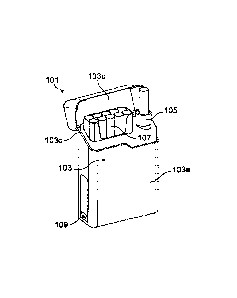
In Figure la, smoking system 101 comprises primary unit 103 and secondary unit
in the
form of holder 105. The primary unit 103 has the form of a flip-top box, with
a base portion 103a
and a lid portion 103b, separated by a hinge 103c. The lid portion 103b is
shown open in Figure
1 a. The hinge 103c runs along a long edge of the top side of the base portion
103a. The holder
5
105 can be stored in the base portion 103a of the primary unit 103 (as shown
in Figure la) by
insertion into a docking port. In Figure la, the docking port for holder 105
is provided at one
side of the base portion 103a, but the docking port could equally be provided
on the opposite
side of the base portion 103a or in the centre of the base portion 103a. In
the embodiment of
Figure la, when the holder 105 is stored in the primary unit 103, the top of
the holder 105
10
protrudes above the top side of the base portion 103a. The lid portion 103b
is, nonetheless,
able to close onto the base portion 103a when the holder 105 is stored in the
primary unit 103,
including when a smoking article is contained in the holder 105.
Alternatively, the top unit of the
holder 105 may be virtually flush with the top side of the base portion 103a.
The primary unit
103 also has storage for smoking articles 107, in this case to one side of the
holder docking
port. A further smoking article may, of course, be stored in the holder 105.
Although not
expressly shown, the docking port for holder 105 may be located on either side
of the base
portion 103a and the storage for smoking articles 107 may be located on the
side opposite the
holder 105. If the docking port for holder 105 is located towards the centre
of the base portion
103a, storage for smoking articles 107 may be located on one or both sides of
the docking port.
Additionally, in the base portion 103a of the primary unit 103 of Figure la,
there is an
interface 109 for receiving a USB plug (not shown). The USB connection may be
used for
charging the power supply in the primary unit, for checking the functionality
or for other
purposes where connection to a computer is required. Such a USB interface, or
indeed any
other suitable interface, may be included on any of the described embodiments.
Additionally or
alternatively, a USB interface, or any other suitable interface, may be
included on the holder,
although this is not shown in Figure la. The USB connection will be discussed
further below.
In Figure 1 b, smoking system 101' comprises primary unit 103' and secondary
unit in the
form of holder 105'. As in Figure la, the primary unit 103' has the form of a
flip-top box, with a
base portion 103a' and a lid portion 103b', separated by a hinge 103c'.
However, in Figure lb,
the hinge runs along a short edge of the top side of the base portion 103a'.
The lid portion 103b'
is shown open in Figure 1 b. The holder 105' can be stored in the base portion
103a' of the
primary unit 103' (as shown in Figure 1 b) by insertion into a docking port.
In Figure 1 b, the
docking port for holder 105' is provided towards the front of the base portion
103a', that is,
furthest from the hinge 103c', but the docking port could equally be provided
towards the rear
end of the base portion 103a', that is, closest to the hinge 103c', or in the
centre of the base
portion 103a'. In the embodiment of Figure 1 b, when holder 105' is stored in
the primary unit
103', the top of the holder 105' may be virtually flush with the top side of
the base portion 103a'.
CA 02817266 2013-05-08
11
WO 2012/065754
PCT/EP2011/005829
The lid portion 103b' is able to close onto the base portion 103a', including
when a smoking
article is contained in the holder 105'. Alternatively, the top of the holder
105' may protrude
above the top side of the base portion 103a'. The primary unit 103' also has
storage for smoking
articles 107, in this case, towards the rear of the base portion 103a', that
is, nearer to the hinge
103c'. A further smoking article may, of course, be stored in the holder. If
the docking port 105'
is located towards the rear of the base portion 103a', the storage for smoking
articles 107' may
be located at the end opposite the holder 105', that is towards the front of
the base portion
103a'. If the docking port for holder 105' is located towards the centre of
the base portion 103a',
storage for smoking articles 107' may be located at one or both ends of the
base portion 103a'.
In Figure lc, smoking system 101" comprises primary unit 103" and secondary
unit in the
form of holder 105". The holder 105" can be stored in the primary unit 103"
(as shown in Figure
1c) by insertion into a docking port. The primary unit 103" comprises a base
portion 103a" and
a lid portion 103b", separated by a hinge 103c". As in Figure 1 b, the hinge
runs along a short
edge of the top side of the base portion 103a", although the hinge could run
along a long edge
of the top side of the base portion 103a". However, in Figure lc, the lid
portion 103b", when
closed, does not cover the entire top side of the base portion 103a". The lid
portion 103b",
when closed, only covers the portion of the base unit which contains the
docking port for the
holder 105". The lid portion 103b" is shown open in Figure lc. In the
embodiment of Figure lc,
when holder 105" is stored in the primary unit 103", the top of the holder
105" may be virtually
flush with the top side of the base portion 103a". Alternatively, the top of
the holder 105" may
protrude above the top side of the base portion 103a". The lid portion 103b"
may be able to
close onto the base portion 103a" when the holder is stored in the docking
port or when the
holder is stored in the docking port and a smoking article (not shown in
Figure 1c) is contained
in the holder 105". The primary unit 103" may also have storage for smoking
articles, although
this is not shown in Figure lc.
In Figure id, smoking system 101" comprises primary unit 103" and secondary
unit in
the form of holder 105". The holder 105¨ can be stored in the primary unit
103¨ (as shown in
Figure 1d) by insertion into a docking port. In Figure id, the docking port
for holder 105¨ is
provided at one side of the base portion 103a", but the docking port could
equally be provided
on the opposite side of the base portion 103a¨ or in the centre of the base
portion 103a¨. The
primary unit 103" and holder 105" together form a single compact unit. In the
embodiment of
Figure id, when the holder 105" is stored in the primary unit 103", the top of
the holder 105"
protrudes above the top side of the primary unit 103". Alternatively, the top
unit of the holder
105" may be virtually flush with the top side of the primary unit 103". In the
embodiment of
Figure id, the primary unit 103" does not have any storage for smoking
articles, although a
single smoking article may be stored in the holder 105". However, additional
storage for
smoking articles could be provided. Additionally, as in Figure la, an
interface 109" is provided
CA 02817266 2013-05-08
12
WO 2012/065754
PCT/EP2011/005829
in the primary unit 103" for receiving a USB plug (not shown).
In the embodiments shown in Figures la, lb, lc and ld, the smoking system
comprises a
primary unit and one separate holder. The smoking system is designed for a
single user. The
holder may be stored in the primary unit. A smoking article may be received in
the holder when
the holder is stored in the primary unit or when the holder is separate from
the primary unit.
Additionally, the primary unit may provide storage for smoking articles. The
storage for smoking
articles may be sized to store between 1 and 20 smoking articles in any
suitable configuration.
The holder and primary unit together form a compact smoking system that can
easily be carried
by a user. The various features of Figures la, lb, lc and ld are
interchangeable.
Figures 2a and 2b show alternative views of a second embodiment of the smoking
system
of the invention. In Figures 2a and 2b, smoking system 201 comprises primary
unit 203
comprising a main part 203a and a separable docking port 203b, and two
secondary units in the
form of holders 205a and 205b. Each holder 205a, 205b may be received in the
primary unit
203. In the embodiment of Figures 2a and 2b, first holder 205a may be received
in a docking
port which is integral with the main part 203a of the primary unit 203. Second
holder 205b may
be received in docking port 203b, which is separate from the main part 203a of
the primary unit
203, but may be attached to one side of the main part 203a via interface 209.
Alternative
connections between the docking port 203b and the main part 203a of the
primary unit 203 are,
of course, possible. Docking port on main part 203a includes a recess 211a
which is designed
to cooperate with a protrusion 213a on holder 205a, for securing the holder
205a in the docking
port 203. Similarly, holder 205b includes a protrusion 213b for cooperation
with a recess 211b in
the docking port 203b, which is separate from the main part 203a of the
primary unit 203. In
addition, a mechanism may be provided for securing a smoking article in the
holder.
In Figure 2a, the holders 205a and 205b are shown received in their respective
docking
ports, and docking port 203b is shown separate from the main part 203a of the
primary unit 203.
In Figure 2b, the holders 205a and 205b are shown separately from their
respective docking
ports and in use with a smoking article 207.
In the embodiment shown in Figures 2a and 2b, the smoking system comprises a
primary
unit and two separate holders. The smoking system is designed to be shared by
two users.
Alternatively, the smoking system can be used by a single user, in which case
one of the
holders acts as a back-up. Holder 205a can be stored directly in main part
203a of the primary
unit. Holder 205b can be stored in docking port 203b which is attachable to
the main part 203a
of the primary unit 203. The holders and primary unit together form a compact
smoking system.
A smoking article may be received in each holder when that holder is connected
to the primary
unit or when the holder is separate from the primary unit. Additionally, the
primary unit may
provide storage for smoking articles, although this is not shown in Figures 2a
or 2b.
Figures 3a and 3b each show a version of a third embodiment of the invention.
In Figure
CA 02817266 2013-05-08
13
WO 2012/065754
PCT/EP2011/005829
3a, smoking system 301 comprises primary unit 303 and a plurality of secondary
units in the
form of holders 305. In Figure 3a, three holders 305i, 305ii and 305iii are
shown connected to
the primary unit 303 and one holder 305iv is shown separate from the primary
unit 303. In
Figure 3a, the primary unit 303 provides docking ports for four holders 305,
but any number of
docking ports could be provided. For example, as many or 40 or 50 docking
ports may be
provided. In other embodiments, between 2 and 10 holders may be docked in
primary unit 303
for charging. The primary unit 303 provides first storage 311 which may be
used to store either
smoking articles (used and unused) or holders, or both smoking articles and
holders. The
primary unit 303 also provides second storage 313 which may also be used to
store either
smoking articles or holders, or both smoking articles and holders.
In Figure 3a, holders 305i and 305ii are shown docked in primary unit 303.
They are each
in use with a smoking article 307 and the power supply in the primary unit is
being used for re-
charging the power supply in the holder (charging mode). Holder 305iii is also
shown docked in
primary unit 303, but without a smoking article. The power supply in the
holder 305iii is being
recharged from the power supply in the primary unit 303 (charging mode).
Holder 305iv is
shown separate from the primary unit 303 and in use with a smoking article
307. The power
supply in holder 305iv is being used to pre-heat the smoking article substrate
(during the pre-
heating mode) or maintain the operating temperature of the smoking article
substrate (during
the smoking mode).
In Figure 3a, primary unit 303 is connected to an external power supply (not
shown) via
connection 315. The external power supply may be used for re-charging the
power supply in the
primary unit, for supplying power to the holders for charging the holders, or
any combination of
those.
In Figure 3a, each docking port in primary unit 303 includes its own interface
309. This
may include a display and a switch for initiating the pre-heating mode when a
smoking article is
received in the holder docked in the docking port.
In Figure 3b, smoking system 301' comprises a modular primary unit 303' and a
plurality
of secondary units in the form of holders 305'. Several configurations are
shown in Figure 3b.
In the first configuration, A, the primary unit 303' comprises a single module
304. The
module 304 provides a docking port for a single holder 305'. In the first
configuration, A, the
holder 305' is shown separate from the module 304 of the primary unit 303' and
in use with a
smoking article 307. The power supply in holder 305' is being used to pre-heat
the smoking
article substrate during the pre-heating mode or to maintain the operating
temperature of the
smoking article substrate during the smoking mode. The module 304 includes its
own interface
309' for its docking port and may also include storage (not shown). The
primary unit 303' is
connected to an external power supply (not shown) via connection 315'.
In the second configuration, B, the primary unit 303' comprises four modules
304. Of
CA 02817266 2013-05-08
14
WO 2012/065754
PCT/EP2011/005829
course, any number of modules may be provided. Again, each module 304 provides
a docking
port for a single holder 305'. In the second configuration, the four modules
are shown connected
to one another in a "nest" formation. In the nest formation, each module may
be connected to 1,
2, 3, 4, 5 or 6 other modules. The connection between modules 304 may be a
magnetic
connection or any other type of suitable connection. In the second
configuration, B, three
holders 305' with smoking articles 307 are shown docked in respective modules
304 and the
primary unit 303' is being used for re-charging the power supply in each
holder. As in
configuration A, each module 304 includes its own interface 309' for its
docking port and may
also include storage (not shown). The primary unit 303' is connected to an
external power
supply (not shown) via connection 315'. Note that only a single power
connection is required for
the primary unit 303', which provides power to all the modules 304.
In the third configuration, C, the primary unit 303' comprises four modules
304. Of course,
again, any number of modules may be provided. Again, each module 304 provides
a docking
port for a single holder 305'. In the third configuration, the four modules
are shown connected to
one another in a "chain" formation. In the chain formation, each module may be
connected to
only 1 or 2 other modules. The connection between modules 304 may be a
magnetic
connection or any other type of suitable connection. In the third
configuration, C, three holders
305' with smoking articles 307 are shown docked in respective modules 304 and
the primary
unit 303' is being used for re-charging the power supply in each holder. As in
configurations A
and B, each module 304 includes its own interface 309' for its docking port
and may also
include storage (not shown). The primary unit 303' is connected to an external
power supply
(not shown) via connection 315'. Note that only a single power connection is
required for the
primary unit 303', which provides power to all the modules 304.
In the embodiment of Figure 3b, each user may have their own holder 305' and
module
304. As users join the group, new modules are added to the configuration. As
users leave the
group, modules are removed from the configuration.
In the embodiments shown in Figures 3a and 3b, the smoking system comprises at
least
one primary unit and a plurality of holders. The smoking system is designed to
be used by many
users. Unlike the embodiments of Figures 1 and 2, the smoking system shown in
Figure 3a may
not necessarily be transportable, and may be permanently positioned in a
location accessible to
a plurality of users.
Each of the embodiments shown in Figures 1 to 3 includes at least one primary
unit and
one or more secondary units. However, a primary unit need not be included in
the smoking
system. In that case, the holder will be connectable directly to an external
power source, such
as a mains supply, or a host computer. This may be via a wired connection such
as a USB
connection. Connection to an in-vehicle charging port is also possible. In
that case, the holder
will include the necessary electronic circuitry to control the charging in the
charging mode, and
CA 02817266 2013-05-08
WO 2012/065754
PCT/EP2011/005829
the heating of the smoking article substrate in the pre-heating mode. Various
features common
to all the illustrated embodiments will now be described.
The power supply in the primary unit may be any suitable power supply. The
primary
power supply may be chargeable by an external source. For example, the primary
unit power
5 supply may be a battery, such as a lithium ion, lithium iron phosphate,
lithium manganese,
nickel cadmium or nickel metal hydride battery. The external source may be an
external
computer connectable to the primary unit via a connection, for example a USB
(Universal Serial
Bus) connection. The external source may be mains electricity supply
connectable to the
primary unit via a plug and socket. The power capability of the primary unit's
power source is
10 preferably 3 to 6 Watts. The requirements that constrain the minimum
size of the primary unit
power supply are energy and charging time.
The electronic circuitry in the primary unit may include a microcontroller, a
microprocessor, a digital signal processor (DSP), an application specific
integrated circuit
(ASIC) or any other programmable digital or analogue circuitry. The electronic
circuitry in the
15 primary unit has a number of functions including: to charge the primary
unit power supply from
an external source. The electronic circuitry may also be arranged to
communicate with a host
via a wired connection, for example USB, or via a wireless connection, for
example Bluetooth to
provide bi-directional transfer of data between the host and the primary and
secondary units.
The communication between the secondary unit and the primary unit may be
facilitated when
the secondary unit is in a docking port on the primary unit or when the
secondary unit is stored
in storage means in the primary unit.
As already mentioned, the primary unit may include an interface for external
connection.
Preferably, the interface operates under an interface standard. The connection
may be a wired
connection such as a USB link, or a wireless connection, such as Bluetooth.
The wired
connection may include a retractable cable. This may be used for charging the
primary power
supply. The connection may alternatively or additionally be used for extra
functionality. For
example, when the primary unit is connected to an external computer, the
operation of the
system may be checked and the user may be advised when maintenance is
required, for
example, when the primary or secondary unit power supply needs to be replaced.
Additionally,
the connection with a computer can allow the user to place an order for more
smoking articles,
download updates for any software, set personal consumption targets for
individual users and
share information. Further extended capabilities may be provided, not limited
to those listed
above. One or both of the primary and secondary units may include a digital
display.
The power supply in the secondary unit provides enough energy to the heating
elements
to increase the temperature of the aerosol-forming substrate to an operating
temperature and to
maintain the aerosol-forming substrate of the smoking article at the operating
temperature, for a
predetermined period of time or predetermined number of puffs taken during the
smoking mode.
CA 02817266 2013-05-08
16
WO 2012/065754
PCT/EP2011/005829
The power supply in the secondary unit may be a battery, a supercapacitor, a
fuel cell or any
other suitable power supply which can provide enough energy to maintain the
substrate at
working temperature for the predetermined period of time or for the
predetermined number of
puffs. In one embodiment, the secondary unit power supply comprises a
plurality of lithium iron
phosphate cells. In another embodiment, the secondary unit power supply
comprises a lithium
polymer battery. The predetermined period of time may be between 5 and 20
minutes. The
predetermined number of puffs may be between 5 and 20 puffs. The power
capability of the
secondary unit's power source is preferably 1 to 3 Watts. The requirements
that constrain the
minimum size of the secondary unit power supply are energy provided per
smoking experience,
charging time and cycle life (that is, how often the power supply will need to
be replaced).
As already mentioned, the secondary unit may include an interface for
connection directly
to an external source. Preferably, the interface operates under an interface
standard. The
connection may be a wired connection such as a USB link, or a wireless
connection, such as
Bluetooth. The wired connection may include a retractable cable. This may be
used for charging
the secondary power supply. The connection may alternatively or additionally
be used for extra
functionality. Preferably, the connection allows bi-directional flow of data.
For example, when
the secondary unit is connected to an external computer, the operation of the
system may be
checked and the user may be advised when maintenance is required, for example,
when the
secondary unit power supply needs to be replaced or the secondary unit needs
to be cleaned.
Further extended capabilities may be provided, not limited to those listed
above.
The electronic circuitry in the secondary unit may include a microcontroller,
a
microprocessor, a digital signal processor (DSP), an application specific
integrated circuit
(ASIC) or any other programmable digital or analogue circuitry. The secondary
unit electronic
circuitry works in conjunction with the primary unit electronic circuitry. The
pre-heating mode
may be initiated when a smoking article is detected in the secondary unit.
This may be detected
by the secondary circuitry or primary circuitry if the secondary unit is in
connection with the
primary unit. Alternatively, a user may manually initiate the pre-heat, for
example, by activating
a switch on the secondary unit. During the smoking mode, the user may begin
the smoking
experience and continue the smoking experience puff by puff. The electronic
circuitry in the
secondary unit controls the heating elements to maintain the substrate at the
operating
temperature, or as close to the operating temperature as possible. The
electronic circuitry in the
secondary unit may be arranged to keep track of the number of puffs taken by
the user, the
amount of time between puffs and the amount of time that the heating elements
have been
energized. When either the number of puffs reaches the maximum number for the
smoking
article (so that the smoking article is depleted), the user has not taken a
puff before the
predetermined time, or the predetermined period of time has expired, but there
are puffs
remaining, a signal from the electronic circuitry notifies the user to return
the secondary unit to
CA 02817266 2013-05-08
17
WO 2012/065754
PCT/EP2011/005829
the primary unit. Then, if appropriate, the power supply in the secondary unit
can be recharged
and the substrate returned to operating temperature. In this way, the user is
able to stop and
start the smoking experience, and restart the smoking experience until the
smoking article is
depleted.
In addition, the electronic circuitry may identify the smoking article in the
secondary unit,
adjust the heating profile based on the smoking article type and determine
when the holder
needs maintenance, for example when the heating elements need to be cleaned.
The electronic
circuitry in the secondary unit can also allow the secondary unit to be
personalized for an
individual's smoking behaviour. For example, duration of the smoking
experience, time of each
puff, time between puffs and intensity of each puff, may be recorded, the
individual's
consumption patterns may be tracked and the individual's preferred smoking
article may be
monitored. This may work in conjunction with a lock on the secondary unit,
which allows only a
particular user to use the secondary unit.
In order for the electronic circuitry in the secondary unit to count the
number of puffs
taken, the electronic circuitry may include a puff sensor for sensing air flow
indicative of a puff.
The sensor may be any suitable type of sensor, for example a thermistor, an
optical device, an
opto-mechanical device, an electro-mechanical device, or a micro electro
mechanical systems
(MEMS) device.
The shape and size of the secondary unit will, to a certain extent, depend on
the size
and shape of the secondary unit power supply. In principle, however, the
secondary unit may be
any suitable shape. Typically, the secondary unit is an elongate cylindrical
unit having a size
only slightly larger than the smoking article. The cross sectional shape of
the secondary unit
may be round, rectangular, or oval. The secondary unit may include a cap for
covering the
smoking article when it is received in the secondary unit, for protection of
the smoking article or
for limiting odour. The secondary unit may include a cap for covering the open
end of the
secondary unit. Typically, when the smoking article is received in the
secondary unit,
approximately half the length of the smoking article protrudes from the
secondary unit. In other
embodiments, less than half of the length of the smoking article protrudes
from the secondary
unit.
The heating element or elements in the secondary unit may be internal or
external
heating elements and are shaped to most effectively heat the aerosol-forming
substrate. There
may be a single heating element or multiple heating elements. The heating
elements may be
made from an electrically resistive material including, but not limited to, a
metal, a metal alloy, a
ceramic or a semiconductor material. The most appropriate form for the heating
element or
elements will depend on the particular aerosol-forming substrate in the
smoking article. The
aerosol-forming substrate is preferably a solid substrate but may,
alternatively, be a liquid or
gas substrate.
CA 02817266 2013-05-08
18
WO 2012/065754
PCT/EP2011/005829
Preferably, the secondary unit is insulated to minimise heat loss during the
smoking
mode. The better insulated the secondary unit, the longer the substrate can
remain at operating
temperature, which can extend the predetermined period of time for the smoking
mode.
Figure 4a shows a pack of lit-end cigarettes. Figure 4b shows one embodiment
of the
smoking system of the present invention, in which the secondary unit in the
form of the holder
may be stored in the primary unit. Figure 4c shows one embodiment of the
smoking system of
the present invention, in which the holder may be stored in the primary unit,
even when a
smoking article is received in the holder. Figures 4a, 4b and 4c are provided
to show the relative
sizes of embodiments of the smoking system of the present invention and a pack
of lit-end
cigarettes.
Figure 4a shows a pack 401 for lit-end cigarettes 403. The lower view in
Figure 4a is a
cross sectional side view. The upper view in Figure 4a is a cross sectional
top view. This pack
has a width of 55 mm, a height of 90 mm and a depth of 24 mm. Figure 4a shows
one example
of a pack of lit-end cigarettes. Generally, packs of lit-end cigarettes have a
height of between
about 60 mm and about 150 mm, more typically a height of between about 70 mm
and about
125 mm. Generally, packs of lit-end cigarettes have a width of between about
12 mm and about
150 mm, more preferably a width of between about 70 mm and about 125 mm.
Generally,
packs of lit-end cigarettes have a depth of between about 6 mm and about 100
mm, more
preferably a depth of between about 12 mm and about 25 mm. Preferably, the
dimensions of
the packs are adapted to the length of the cigarettes, and the collation of
the cigarettes.
Packs of lit-end cigarettes may be in the shape of a rectangular
parallelepiped, with right-
angled longitudinal and right-angled transverse edges. Alternatively, the pack
may comprise
one or more rounded longitudinal edges, rounded transverse edges, bevelled
longitudinal edges
or bevelled transverse edges, or combinations thereof. Alternatively, the pack
may have a non-
rectangular transversal cross section, for example polygonal such as
triangular or hexagonal, or
oval, semi-oval, circular or semi-circular. The packs may be used to package
smoking articles
including, but not limited to, conventional lit-end cigarettes, cigars or
cigarillos, heated smoking
articles comprising a combustible fuel element or heat source and an aerosol-
generating
substrate (for example cigarettes of the type disclosed in US-A-4,714,082) and
smoking articles
for use with electrical smoking systems (for example cigarettes of the type
disclosed in US-A-
5,692,525).
Through an appropriate choice of the dimensions thereof, packs may be designed
to hold
different total numbers of smoking articles, or different arrangements of
smoking articles. Packs
may hold smoking articles of the same type or brand, or of different types or
brands. In addition,
both filterless smoking articles and smoking articles with various filter tips
may be contained, as
well as smoking articles of differing length and diameter. In addition, the
smoking articles may
differ in strength of taste, resistance to draw and total particulate matter
delivery. The pack may
CA 02817266 2013-05-08
19
WO 2012/065754
PCT/EP2011/005829
comprise more than one of the different types of smoking articles listed
above.
Figure 4b shows a first embodiment of a smoking system according to the
invention. The
lower view in Figure 4b is a cross sectional side view. The upper view in
Figure 4b is a cross
sectional top view. The system comprises a primary unit 405 and a holder 407.
The primary unit
includes a primary power supply in the form of battery 409, storage for
smoking articles 411,
and a docking port 413 for receiving the holder. The holder includes heating
elements, indicated
schematically at 415. In this embodiment, when the holder is stored in the
docking port of the
primary unit, the lid portion (not shown) can be closed. However, when the
holder is stored in
the docking port of the primary unit with a smoking article is received in the
holder (as shown in
Figure 4b), the lid portion cannot be closed. The smoking system has a width
of 56 mm, a
height of 95 mm and a depth of 25 mm.
Figure 4c shows a second embodiment of a smoking system according to the
invention.
The lower view in Figure 4c is a cross sectional side view. The upper view in
Figure 4c is a
cross sectional top view. The system comprises a primary unit 405' and a
holder 407'. The
primary unit includes a battery 409', storage for smoking articles 411', and a
docking port 413'
for receiving the holder. The holder 407' includes heating elements, indicated
schematically at
415'. In this embodiment, when the holder is stored in the docking port of the
primary unit, even
with a smoking article received in the holder (as shown in Figure 4c), the lid
portion (not shown)
can be closed. This is because the holder 407' has a different construction
from holder 407, in
particular the heating elements are positioned differently. The smoking system
has a width of 56
mm, a height of 95 mm and a depth of 25 mm.
It can be seen from Figures 4a, 4b and 4c that at least two embodiments of the
smoking
system of the present invention are of a similar size and shape as a pack of
lit-end cigarettes.
Other embodiments of the smoking system may be of a similar size and shape to
other pack
sizes and shapes, as described above. All the components required for the
smoking experience
are contained in the single compact unit.
Operation of the electrically heated smoking system according to an embodiment
of the
present invention will now be described with reference to Figure 5. Figure 5
is a graph of power
used W and temperature T versus time t for the pre-heating and smoking modes.
First, the user inserts a smoking article into the secondary unit. At this
time, the secondary
unit can be connected to, or separate from, the primary unit.
Second, the secondary unit is connected to the primary unit (if not already
connected) (or
an alternative source of power) and the primary power supply in the primary
unit begins to
charge the secondary power supply in the secondary unit. The charging time
will depend on the
details of the smoking system, but is not more than approximately 5 minutes in
a preferred
embodiment. The order of the first two steps may be reversed. For example, the
secondary unit
may be stored in or on the primary unit when not in use, so that the secondary
power supply is
CA 02817266 2013-05-08
WO 2012/065754
PCT/EP2011/005829
fully charged and the secondary unit is ready for a user to initiate the
smoking experience at any
time. In that case, the secondary power supply in the secondary unit is
charged before a
smoking article is inserted into the portable secondary unit.
Third, once the secondary power supply is fully charged (this can be indicated
by a signal
5
on the primary or secondary unit), the user may begin the pre-heating mode.
At this stage, the
user may remove the portable secondary unit from the primary unit or the
secondary unit may
remain connected to the primary unit. Additionally, the pre-heating mode may
be initiated prior
to or at the same time that the charging mode begins. The pre-heating mode may
be started by
the user pressing a button or flipping a switch when he or she is ready to
begin the smoking
10
experience. Alternatively, the user may begin the pre-heating mode by shaking
the unit a
predetermined number of times to begin the pre-heat phase. At the beginning of
the pre-heating
mode, at time 0 in the graph of Figure 5, the secondary power supply is then
connected to the
heating elements in the secondary unit, under control of the electronic
circuitry in the secondary
unit and, optionally, the primary unit. The heating elements are energized
until the substrate in
15
the smoking article reaches the desired operating temperature Ti (e.g.,
between approximately
150 and 250 C). During the pre-heating mode (shown by the shaded box in
Figure 5), the
temperature of the substrate is raised rapidly, but in a controlled manner in
order to avoid
overshoot. In one embodiment, a temperature sensor is located in the secondary
unit. The
primary unit may also include a temperature sensor. In another embodiment, the
primary unit or
20
the secondary unit may detect that the substrate has reached the desired
operating temperature
Ti after an energizing period t1 has elapsed. The energizing period may be
between
approximately 10 seconds and approximately 150 seconds. At the end of this pre-
heating
period, t1 in Figure 5, electronic circuitry in the secondary unit may
generate a signal to indicate
that the pre-heating period mode is complete and that the user can begin the
smoking
experience.
Fourth, the user may now remove the portable secondary unit (with the received
smoking
article) from the primary unit, if not already removed, to begin the smoking
mode. This is at time
t1 in the graph of Figure 5. During the smoking mode, the secondary power
supply in the
secondary unit, is used to maintain the substrate at or close to operating
temperature Ti. The
heating elements provide enough heat to the substrate to maintain the
substrate at operating
temperature, thereby compensating for heat losses through the secondary unit,
and as air is
drawn through the secondary unit during each puff. The electronic circuitry in
the secondary unit
records the time elapsed, the time between puffs and/or the number of puffs
taken, since the
portable secondary unit was removed from the primary unit at time t1.
In Figure 5, three plots are shown during the smoking mode. The first, solid
line indicates
the temperature when the secondary unit is insulated. This is the preferred
embodiment and, as
can be seen from Figure 5, maintains the substrate very close to the operating
temperature Ti
CA 02817266 2013-05-08
21
WO 2012/065754
PCT/EP2011/005829
and power W1. The second, dotted line indicates the temperature when the
secondary unit is
not insulated. In that embodiment, the substrate is still maintained close to
the operating
temperature Ti but there is more heat loss than when the secondary unit is
insulated. The third,
dashed line indicates the temperature without any secondary power supply in
the secondary
unit. In that arrangement, the temperature of the substrate falls away quickly
during the smoking
mode.
Fifth, the electronic circuitry in the secondary unit either detects that the
maximum number
of puffs (e.g., between approximately 5 and 20 puffs per smoking article) has
been reached, or
the maximum amount of time for the smoking mode (e.g., approximately 5 to 20
minutes after
the user has removed the holder from the primary unit) has expired, or the
maximum amount of
time between puffs (e.g., approximately 30 sec to 5 minutes) has expired. This
is time t2 in the
graph of Figure 5. In the first case, if the electronic circuitry in the
secondary unit detects that
the maximum puff count has been reached for the smoking article, the
electronic circuitry will
stop energizing the heating elements to maintain the substrate at the desired
operating
temperature. If the maximum number of puffs have been taken by the user during
the smoking
mode, the electronic circuitry in the secondary unit generates a signal to the
user indicating that
the maximum number of puffs have been taken. This signal may be in the form of
a display on
the portable secondary unit (for example indicating the number of puffs
remaining), one or more
indicator lights, such as LEDs, which switch on or off as the puffs are taken,
an audible
notification such as a buzzer, a silent notification such as a vibration, or
any other suitable
signal. In the second case, if the electronic circuitry in the secondary unit
detects that the
maximum amount of time for the smoking mode has expired, the electronic
circuitry will stop
maintaining the operating temperature at the substrate and will generate a
signal to the user
indicating that time for the smoking mode has expired. This signal can be any
suitable signal as
described above. In the third case, if the maximum amount of time allowed for
the user to take
consecutive puffs has expired, the electronic circuitry generates a signal to
the user indicating
that a puff has not been taken during the allowed time. This signal can be any
suitable signal as
described above. The signals can indicate that the secondary unit should be
returned to the
primary unit for charging.
Sixth and finally, the user may reconnect the portable secondary unit and the
primary
power supply and the primary unit begins to recharge the secondary power
supply in the
portable secondary unit again. Once the secondary power supply in the
secondary unit is fully
charged, if puffs remain, the user can restart the smoking experience from the
third step. Thus,
the user can start and stop the smoking experience.
As described, embodiments of the invention provide a number of advantages.
First, by
dividing the system, in particular the power supply, into two portions, the
size of the secondary
unit can be reduced. Second, the secondary unit can facilitate puff on demand,
and the smoking
CA 02817266 2013-05-08
22
WO 2012/065754
PCT/EP2011/005829
experience can be started and stopped. Embodiments for a single user, which
have a size and
shape similar to that of a pack of lit-end cigarettes, are advantageous since
there will need to be
minimal disruption to the user's smoking behaviour for the user to adopt the
product. In addition,
the user need only carry the single unit which provides all the components
required for the
smoking experience. Embodiments which provide a plurality of secondary units
for use by a
plurality of users are advantageous since they facilitate social interaction.
Embodiments in
which the secondary unit is personalised allow the user to prevent
unauthorised use and the
performance may be adapted to best suit the user. Figure 6 shows a flow
diagram illustrating an
embodiment of the method of the present invention. Figure 6 shows an
embodiment of the
method for charging the secondary power supply in the charging mode. During
the charging
mode, the secondary unit must be connected to the primary unit (or primary
power supply if
there is no primary unit). The charging of the secondary power supply is
controlled by the
secondary circuitry in the secondary unit.
In the embodiment of Figure 6, the determination of when the secondary power
supply is
sufficiently charged is based on a calculated estimate of the electrical power
required for
operating the secondary unit in both the pre-heating mode and the smoking
mode. In the
embodiment of Figure 6, this calculation is based on three technical
parameters 601, 602, 603.
The first technical parameter 601 is a pre-specified number of puffs to be
taken by a user during
the smoking mode. That pre-specified number of puffs is preferably close to
the number of puffs
for a lit-end smoking article. For example, the pre-specified number of puffs
may be between 10
puffs and 20 puffs, even more preferably 15 puffs.
The second technical parameter 602 is the electrical power required for the
pre-heating
mode. This may depend on the physical properties of the smoking article and
the aerosol-
forming substrate, for example, but not limited to, the density or structure
of the aerosol-forming
substrate. This may also depend on the energizing period to reach the desired
operating
temperature. The value of the second technical parameter 602 may be determined
empirically,
for example, by laboratory test runs using different substrates.
The third technical parameter 603 is consumer-specific information relating to
the smoking
mode, for example, but not limited to the puff strength and puff length. Such
consumer-specific
information affects the electrical power required for operating the secondary
unit during one puff
in the smoking mode.
Typically, the first and second technical parameters 601, 602 are required for
the
calculated estimate of when the secondary power supply is sufficiently
charged. Typically, the
third technical parameter 603 is preferred, but not required. One of the
advantages of the
secondary circuitry controlling supply of power during the charging mode is
that the secondary
circuitry may have gathered consumer-specific information. Therefore, the
consumer-specific
information does not need to be transferred to the primary circuitry.
CA 02817266 2013-05-08
23
WO 2012/065754
PCT/EP2011/005829
At step 604, the required electrical power for both the pre-heating mode and
the smoking
mode is calculated based on the values of the three technical parameters 601,
602, 603. This
calculation 603 may be based on an integration calculation or sum of the
values for each
technical parameter. Preferably, the calculation is performed by the secondary
circuitry, in which
case, the determined value of the required electrical power must be
communicated to the
primary unit, at step 605, since the secondary power supply is being re-
charged from the
primary power supply. This required electrical power may be considered a
minimum electrical
power.
Once it is determined that the secondary power supply has sufficient charge to
increase
the temperature of the aerosol-forming substrate to the operating temperature
in the pre-heating
mode and to maintain the temperature of the aerosol-forming substrate at
substantially the
operating temperature during the smoking mode, this may be signalled to the
user, at step 606.
For example, the primary unit or secondary unit may indicate that the
secondary unit has
sufficient charge. This may be by way of an LED light or an LCD display, for
example.