Note: Descriptions are shown in the official language in which they were submitted.
CA 02817356 2013-05-08
WO 2012/074124 PCT/JP2011/078008
1
DESCRIPTION.
TITLE OF THE INVENTION
TRANSMISSION MANAGEMENT SYSTEM, PROGRAM,
COMPUTER READABLE INFORMATION RECORDING MEDIUM, PROGRAM
PROVIDING SYSTEM, AND MAINTENANCE SYSTEM
TECHNICAL FIELD
The present invention relates to a configuration
for managing communication between a certain request source
terminal and a certain destination terminal from among
certain transmission terminals by informing the
destination terminal which is a start request target for
the telephone call of a start request for the telephone call
from the request source terminal.
BACKGROUND ART
Recently, along with a recent tendency of
reducing business trip costs and business trip man hours,
transmission systems for carrying out a TV conference using
a communication network such as the Internet have become
spread. In such a transmission system, when a telephone
call is carried out between plural transmission terminals,
image data and voice data are transmitted therebetween, and
thus, a TV conference can be carried out.
CA 02817356 2015-06-05
76311-32
2
Further, by displaying a destination list on the side
of a request source terminal which is a request source of a
telephone call for the purpose that the user of the request
source terminal can easily select a desired destination
terminal from among plural candidates for the telephone call,
the user of the request source terminal can select the desired
destination terminal (see Japanese Laid-Open Patent Application
No. 2006-074453).
However, a first user may be troubled when a second
user registers the transmission terminal of the first user in
the second user's destination list without approval from the
first user, and the first user receives a start request for a
telephone call from the second user.
SUMMARY OF INVENTION
According to an aspect of the present invention,
there is provided a transmission management system which
manages communication between a request source terminal and a
destination terminal from among plural transmission terminals,
by sending a start request for the communication from the
request source terminal which is a start request source for the
communication to the destination terminal which is a start
request target for the communication, comprising: a destination
list management part configured to manage a destination list
indicating a candidate for the destination terminal of the
request source terminal, by associating terminal identification
information for identifying the request source terminal with
terminal identification information for identifying the
destination terminal which is the destination candidate capable
of carrying out the communication with the request source
CA 02817356 2015-06-05
76311-32
2a
terminal; a reception part configured to receive terminal
identification information of a request target terminal that is
a request target of an addition request for adding a
destination candidate, the terminal identification information
of the request target terminal being transmitted from a PC
terminal that is not managed by the destination list management
part and is capable of transmitting an addition request for
adding and associating, with terminal identification
information of a request source terminal in the destination
list, terminal identification information of a destination
terminal, the terminal identification information of the
request target terminal to be received by the reception part
being input by a user of the PC terminal for transmitting the
addition request from the PC terminal; and a transmission part
configured to transmit, based on the terminal identification
information of the request target terminal, an approval request
for requesting for causing the approval request to be received
by the request target terminal, wherein the reception part is
configured to receive a request response transmitted from the
request target terminal in response to the approval request, in
a case where the request response indicates to approve the
addition request, the destination list management part is
configured to add and associate the terminal identification
information of the request target terminal received from the PC
terminal, as the terminal identification information of the
destination terminal, with the terminal identification
information of the request source terminal, and manage the
added terminal identification information, the transmission
part is configured to transmit the added terminal
identification information of the request target terminal to
CA 02817356 2015-06-05
76311-32
2b
the request source terminal so that the request source terminal
is able to start communication with the added request target
terminal based on the transmitted terminal identification
information of the request target terminal, and the terminal
identification information of the request target terminal to be
received by the reception part being input by a user to the PC
terminal for transmitting the addition request from the PC
terminal is received after the PC terminal logs in using the
terminal identification information of the request source
terminal.
According to an embodiment of the present invention,
a transmission management system manages communication between
a request source terminal and a destination terminal from among
plural transmission terminals, by sending a start request for
the communication from the request source terminal which is a
start request source terminal to the destination terminal which
is a start request target for the communication. The
transmission management system includes a destination list
management part configured to manage a destination list
indicating a
CA 02817356 2013-05-08
WO 2012/074124 PCT/JP2011/078008
3
candidate for a destination of the request source terminal,
by associating, for identification information of the
request source terminal, identification information of the
destination terminal which is the destination candidate
capable of carrying out the communication with the request
source terminal; a reception part configured to receive,
from the request source terminal which is an addition
request source requesting to add a certain transmission
terminal as a destination candidate, an addition request
for the destination candidate, the identification
information of the request source terminal and the
identification information of a request target terminal
which is an addition request target for the destination
candidate; and a transmission part configured to inform the
request target terminal of an approval request for
requesting the request target terminal to approve the
addition request, and transmitting the identification of
the request source terminal. The reception part is
configured to receive the addition request response from
the request target terminal in response to the addition
request, and in a case where the addition request response
indicates to approve the addition request, the destination
list management part is configured to additionally
associate the identification information of the request
target terminal as the identification information of the
CA 02817356 2015-06-05
76311-32
4
destination terminal with the identification information
.of the request source terminal, and manage the
identification information.
Features and advantages of some embodiments of the
present invention will become more apparent from the
following detailed description when read in conjunction
with the accompanying drawings.
BRIEF DESCRIPTION OF DRAWINGS
FIG. 1 is a general view of a transmission system
according to a first embodiment of the present invention;
FIG. 2 is a general view showing a state where
image data, voice data and various sorts of management
information are transmitted in the transmission system;
FIG. 3A illustrates a concept of image quality
of image data (low resolution);
FIG. 3B illustrates a concept of image quality
of image data (medium resolution);
FIG. 3C illustrates a concept of image quality
of image data (high resolution);
FIG. 4A shows an external appearance of one
example of a transmission terminal according to the first
embodiment;
FIG. 4B shows an external appearance of another
example of a transmission terminal according to the first
CA 02817356 2013-05-08
WO 2012/074124 PCT/JP2011/078008
embodiment;
FIG. 5 shows a hardware configuration of a
transmission terminal according to the first embodiment;
FIG. 6 shows a hardware configuration of each of
5 a transmission management system, a relay apparatus, a
program providing system and a maintenance system according
to the first embodiment;
FIG. 7 is a functional block diagram of the
transmission terminal and the transmission management
system included in the transmission system according to the
first embodiment;
FIG. 8 shows a concept of a terminal
authentication management table;
FIG. 9 shows a concept of a terminal management
table;
FIG. 10 shows a concept of a destination list
management table;
FIG. 11 shows a concept of an addition request
management table;
FIG. 12 is a sequence diagram showing a process
in a preparation step for starting a telephone call between
transmission terminals;
=
FIG. 13 shows .a concept of a destination list;
FIG. 14 is a sequence diagram showing a process
of adding a destination candidate;
CA 02817356 2013-05-08
WO 2012/074124 PCT/JP2011/078008
6
FIG. 15 shows a concept of an addition request
reception screen page;
FIG. 16 is a flowchart showing a process of
approval or rejection;
FIG. 17 shows a concept of an addition approval
request screen page;
FIG. 18 shows a concept of an addition completion
screen page;
FIG. 19 is a general view of a transmission system
according to a second embodiment of the present invention;
FIG. 20 is a functional block diagram of a
transmission management system and a transmission terminal
management system included in the transmission system
according to the second embodiment;
FIG. 21 is a sequence diagram showing a process
of carrying out an addition approval request from a user
PC terminal;
FIG. 22 shows a concept of a destination list;
FIG. 23 shows a concept of an addition request
reception screen page;
FIG. 24 shows a sequence diagram of a process of
carrying out an addition request response from a user PC
terminal;
FIG. 25 shows a concept of an addition approval
request screen page;
CA 02817356 2013-05-08
WO 2012/074124 PCT/JP2011/078008
7
FIG. 26 is a concept showing a failure screen page
at a PC according to a third embodiment of the present
invention; and
FIG. 27 is a concept showing a failure screen page
at a terminal according to the third embodiment of the
present invention.
DESCRIPTION OF EMBODIMENTS
According to an embodiment of the present
invention, before a destination candidate is included in
a destination list, a management system inquires of a
transmission terminal corresponding to the destination =
candidate whether inclusion of the transmission terminal
in the destination list is approved. Thereby, the user's
own transmission terminal can be prevented from being
included in the destination list of another person without
approval from the user.
Below, with reference to figures, embodiments of
the present invention will be described.
[First Embodiment]
With reference to FIGS. 1 through 18, a first
embodiment of the present invention will now be described.
<<Overall Configuration of First Embodiment>>
CA 02817356 2013-05-08
WO 2012/074124 PCT/JP2011/078008
8
FIG. 1 shows a general configuration of a
transmission system according to the first embodiment of
the present invention. FIG. 2 shows a concept of a state
where image data, voice data and various sorts of management
information are transmitted and received in the
transmission system. FIGS. 3A, 3B and 30 illustrate a
concept of image quality of image data.
The transmission system 1 maybe a communication
system mutually transmitting information, feelings or such
between plural transmission terminals 10 via a transmission
management system 50. The communication system is a system
for mutually transmitting information, feelings or such
between plural communication terminals (corresponding to
"transmission terminals") via a communication management
system (corresponding to a "transmission management
system"), and may be used as a TV conference system, a
teleconference system or such, for example.
According to the first embodiment, the
transmission system, the transmission management system
and the transmission terminals will be described supposing
a TV conference system as one example of the communication
system, supposing a TV conference management system as one
example of the communication management system and
supposing a TV conference terminal as one example of the
communication terminal. That is, the transmission
CA 02817356 2013-05-08
WO 2012/074124 PCT/JP2011/078008
9
terminals and the transmission management system according
to the first embodiment of the present invention may be
applied not only to a TV conference system, but also another
communication system. It is noted that the above-mentioned
"TV conference" may also be called "video conference" or
such.
Further, according to the first embodiment, a
case will be described where respective users of the
transmission system 1 belong to four offices, i.e., aTokyo
office (users "a"), an Osaka office (users "b"), a New York
office (users "c") and a Washington, D.C. office (users
"d").
The transmission system 1 shown in FIG. 1
includes plural transmission terminals (10aa, 10ab, ...),
display devices (120aa, 120ab, ...) for the respective
transmission terminals (10aa, 10ab, ...), plural relay
apparatuses (30a, 30b, 30c and 30d), a transmission
management system 50, a program providing system 90 and a
maintenance system 100.
The plural transmission terminals (10aa,
10ab, ...) carry out transmission and reception of image
data and voice data as one example of content data.
It is noted that hereinafter, "transmission
terminals" may be simply referred to as "terminals".
Further, any terminal of the plural terminals (10aa,
CA 02817356 2013-05-08
WO 2012/074124 PCT/JP2011/078008
10ab, ...) may be referred to as a "terminal 10". Any
display device of the plural display devices (120aa,
120ab, ...) may be referred to as a "display device 120".
Any one of the plural relay apparatuses (30a, 30b, 30c and
5 30d) maybe referred to as a "relay apparatus 30". Further,
the terminal acting as a request source requesting a start
of a TV conference may be referred to as a "request source
terminal", and the terminal acting as a destination (relay
destination) which is a request target may be referred to
10 as a "destination terminal".
Further, as shown in FIG. 2, in the transmission
system 1, between a transmission source terminal and a
destination terminal, a management information session
"sei" is established for transmitting various sorts of
management information via the transmission management
system 50. Further, between the request source terminal
and the destination terminal, four sessions are established
for transmitting four sorts of data, i.e., image data of
high resolution, image data of medium resolution, image
. data of low resolution and voice data, respectively, via
the relay apparatus 30. These four sessions may be
collectively referred to as an image and voice data session
"sed" (i.e., a session for image data and voice data).
Resolution of image data used in the first
embodiment will now be described. As shown in FIG. 3A, an
CA 02817356 2013-05-08
WO 2012/074124 PCT/JP2011/078008
11
image of low resolution as a base image has a configuration
of 160 pixels (in a horizontal direction) by 120 pixels (in
a vertical direction). As shown in FIG. 3B, an image of
medium resolution has a configuration of 320 pixels (in the
horizontal direction) by 240 pixels (in the vertical
direction). As shown in FIG. 3C, an image of high
resolution has a configuration of 640 pixels (in the
horizontal direction) by 480 pixels (in the vertical
direction). In a case where a narrow band path is used,
image data of low image quality including only image data
of low resolution as a base image is relayed. In a, case
where a band is relatively wide, image data of medium image
quality including image data of low resolution as a base
image and image data of medium resolution is relayed. In
a case where a band is very wide, image data of high image
quality including image data of low resolution as a base
image, image data of medium resolution and image data of
high resolution is relayed.
The relay apparatuses 30 shown in FIG. 1 carry
out relaying of content data between the plural terminals
10. The transmission management system 50 manages, in a
unifying manner, login authentication requested by the
terminals 10, management of telephone-call situations of
the terminals 10, management of a destination list,
communication situations of the relay apparatuses 30, and
CA 02817356 2013-05-08
WO 2012/074124 PCT/JP2011/078008
12
so forth. It is noted that images of the image data may
be video (moving picture) images or static images, and may
include both video (moving picture) images and static
images.
Plural routers (70a, 70b, 70c, 70d, 70ab, 70cd)
select optimum paths for image data and voice data. It is
noted that hereinafter, any one of the plural routers (70a,
70b, 70c, 70d, 70ab, 70cd) may be referred to as a "router
70".
The program providing system 90 includes a HD
(Hard Disk) 204 (described later), stores a program for the
terminals 10 for each of the terminals 10 to carry out
various functions (or causing each of the terminals 10 to
function as various functional parts), and is capable of
transmitting the program for the terminals to each of the
terminals 10. Further, the HD 204 of the program providing
system 90 also stores a program for the relay apparatuses
30 for each of the relay apparatuses 30 to carryout various
functions (or causing each of the relay apparatuses 30 to
function as various functional parts), and capable of
transmitting the program for the relay apparatuses to each
of the relay apparatuses 30. Further, the HD 204 of the
program providing system 90 also stores a program for
transmission management for the transmission management
system 50 to carry out various functions (or causing the
CA 02817356 2013-05-08
WO 2012/074124 PCT/JP2011/078008
13
transmission management system 50 to function as various
functional parts), and capable of transmitting the program
for transmission management to the transmission management
system 50.
The maintenance system 100 is a computer carrying
out maintenance or management of at least one of the
terminals 10, the relay apparatuses 30, the transmission
management system 50 and the program providing system 90.
For example, in a case where the maintenance system 100 is
installed in the home country, and the terminals 10, the
relay apparatuses 30, the management system 50 or the
program providing system 90 are(is) installed abroad, the
maintenance system. 100 carries out maintenance, management
or such of at least one of the terminals 10, the relay
apparatuses 30, the management system 50 and the program
providing system 90 remotely via a communication network
2. Further, the maintenance system 100 carries out
maintenance such as management Or such of a model number,
a production number, a sales destination, maintenance
inspection or a history of failures of at least one of the
terminals 10, the relay apparatuses 30, the management
system 50 and the program providing system 90 without using
the communication network 2.
The terminals (10aa, 10ab, lOac, ...), the relay,
apparatuses 30a and the router 70a are connected together
CA 02817356 2013-05-08
WO 2012/074124 PCT/JP2011/078008
14
by a LAN 2a in such a manner that they can carry out mutual
communication. The terminals (10ba, lObb, 10bc, ...), the
relay apparatus 30b and the router 70b are connected
together by a LAN 2b in such a manner that they can carry
out mutual communication. The LAN 2a and the LAN 2b are
connected together by a private line 2ab including the
router 70ab in such a manner that they can carry out mutual
communication, and are built in a certain area A. For
example, the area A is Japan, the LAN 2a is built in Tokyo
office, and the LAN 2b is built in the Osaka office.
On the other hand, the terminals (10ca, lOcb,
lOcc, ...), the relay apparatuses 30c and the router 70c
are connected together by a LAN 2c in such a manner that
they can carry out mutual communication. The terminals
(10da, 10db, 10dc, ...), the relay apparatuses 30d and the
router 70d are connected together by a LAN 2d in such a manner
that they can carry out mutual communication. The LAN 2c
and the LAN 2d are connected together by a private line 2cd
including the router 70cd in such a manner that they can
carry out mutual communication, and are built in a certain
area B. For example, the area B is the USA, the LAN 2c is
built in the New York office, and the LAN 2d is built in
the Washington, D.C. office. The area A and the area B are
connected together in such a manner that they can carry out
mutual communication by the Internet 2i via the routers
CA 02817356 2013-05-08
WO 2012/074124 PCT/JP2011/078008
(70ab and 70cd), respectively.
Further, the transmission management system 50
and the program providing system 90 are connected with the
terminals 10 and the relay apparatuses 30 in such a manner
5 that they can carry out mutual communication by the Internet
2i. The transmission management system 50 and the program
providing system 90 may be installed in the area A or the
area B, or may be installed in another area.
It is noted that in the first embodiment, the
10 communication network 2 includes the LAN 2a, the LAN 2b,
the private line 2ab, the Internet 2i, the private line 2cd,
the LAN 2c and the LAN 2d. In the communication network
2, not only wired parts, but also wireless parts where
communication is carried out wirelessly by WiFi (Wireless
15 Fidelity), Bluetooth (registered trademark), or such, may
be included.
Further, in FIG. 1, four sets of numerals below
each of the terminals 10, the relay apparatuses 30, the
transmission management system 50, the routers 70 and the
program providing system 90 show an IF address according
to the common IPv4 in a simplified manner. For example,
the IF address of the terminal 10aa is "1.2.1.3". IPv6 may
be used instead of IPv4. However, for the sake of
simplifying the description, the description will be made
using IPv4.
CA 02817356 2013-05-08
WO 2012/074124 PCT/JP2011/078008
16
It is noted that the respective terminals 10 may
be used not only for a telephone call between the plural
offices or different rooms in a same office, but also for
a telephone call within a same room, between an outdoor
person and an indoor person or between an outdoor person
and another outdoor person. In a case where the respective
terminals 10 are used outdoors, communication may be
carried out wirelessly by using a cell phone communication
network or such.
<<Hardware Configuration of First Embodiment>>
First, a hardware configuration of the first
embodiment will be described. FIG. 4A shows one example
of an external appearance of the terminal 10 according to
the first embodiment. Below, a longitudinal direction of
the terminal 10 is referred to as an X-axis direction, a
direction perpendicular to the X-axis direction on the
horizontal plane is referred to as a Y-axis direction and
a direction (vertical direction) perpendicular to the
X-axis direction and the Y-axis direction is referred to
as a Z-axis direction.
As shown in FIG. 4A, the terminal 10 includes a
housing 1100, an arm 1200 and a camera housing 1300. On
a rear side wall 1110 of the housing 1100, an air suction
surface (not shown) including plural air suction holes is
CA 02817356 2013-05-08
WO 2012/074124 PCT/JP2011/078008
17
provided. On a front side wall 1120 of the housing 1100,
an air discharge surface 1121 including plural air
discharge holes is provided. Thereby, as a result of a
cooling fan (not shown) provided in the inside of the housing
1100 being driven, air behind the terminal 10 is taken in
via the air suction surface, and the air is discharged to
the front side of the terminal 10 via the air discharge
surface 1121. On a right side wall 1130 of the housing 1100,
a sound collecting hole 1131 is formed, and voice, sound,
noise or such is collected by means of a microphone 114 (see
FIG. 5, described later) provided in the inside of the
housing 1100 described later.
On a top surface of the housing 1100 at an area
near the right side wall 1130, an operations panel 1150 is
provided. On the operations panel 1150, plural operating
buttons (108a through 108e) described later, a power supply
switch 109 described later and an alarm lamp 119 described
later are provided. Also, on the operations panel 1150,
a sound output surface 1151 including plural sound output
holes formed for passing through output sound from a speaker
115 provided in the inside of the housing 1100 described
later is provided. Further, on the top surface of the
housing 1100 at an area near a left side wall 1140, a holding
hole 1160 as a depression for receiving the arm 1200 and
the camera housing 1300 is provided. On the right side wall
CA 02817356 2013-05-08
WO 2012/074124 PCT/JP2011/078008
18
1130 of the housing 1100, plural connection holes (1132a
through 1132c) are provided for electrically connecting
cables to an external apparatus connecting I/F 118
described later. On the other hand, on the left side wall
1140 of the housing 1100, a connection hole (not shown) is
provided for electrically connecting a cable 120c for a
display device 120 to the external apparatus connecting I/F
118.
It is noted that hereinafter, in a case where any
operating button of the operating buttons (108a through
108e) is referred to, this will be generally referred to
as an "operating button 108". Similarly, in a case where
any connection hole of the connection holes (1132a through
1132e) is generally referred to, this-will be referred to
as a "connection hole" 1132.
The arm 1200 is mounted on the housing 1100 via
a torque hinge 1210, and is configured to be able to rotate
vertically in a range of a tilt angle el of 135 with
respect to the housing 1100. FIG. 4A shows a state where
the tilt angle el is 90 .
A camera 112 is provided in the inside of the
camera housing 1300, and the user, a document, a room and
so forth can be photographed. Further, a torque hinge 1310
is formed in the camera housing 1300. The camera housing
1300 is mounted on the arm 1200 via the torque hinge 1310,
CA 02817356 2013-05-08
WO 2012/074124 PCT/JP2011/078008
19
and thus a configuration is provided such that the camera
housing 1300 can be rotated vertically and horizontally,
in a range of a pan angle 92 of 180 and in a range of
a tilt angle e3 of 45 , where FIG. 4A shows a state of
FIG. 4E shows another example of an external
appearance of the terminal 10. As shown in FIG. 4B, in this
example, the terminal 10 includes a housing 11021, an arm
11074 and a camera housing 11075. On an approximately
entire surface of a front side wall 11021a of the housing
11021, plural air suction holes 11021e are formed. On an
approximately entire area of a rear side wall 11021b of the
housing 11021, plural air discharge holes (now shown) are
formed. Thereby, due to a cooling fan (not shown) provided
in the inside of the housing 11021, air in front of the
terminal 10 is suctioned via the air suction holes 11021e,
and is discharged to the rear side of the terminal 10 via
the air discharge holes. A sound collection hole 11021f
is formed at a central part of the front side wall 11021a,
and voice, sound, noise or such is collected by a microphone
114 in the inside of the housing 11021 via the sound
collection hole 11021e. On a lower side surface of the
housing 11021, a connection hole 11021g corresponding to
a hardware I /F for connecting a cable terminal of an external
apparatus (such as a camera, a microphone, a speaker or such
CA 02817356 2013-05-08
WO 2012/074124 PCT/JP2011/078008
provided in the outside of the terminal) is formed.
An operations panel 11022 is formed on the left
side, viewed from the front side, on the housing 11021. On
the operations panel 11022, operating buttons 108 and a
5 power supply switch 109, described later, are provided, and
also, plural sound output holes 11022f for passing
therethrough output sound from a speaker 115 (described
later) provided in the inside of the terminal 10 are provided.
Further, at a right side area on the housing 11021, viewed
10 from the front side, a holding part 11021p is formed as a
depression for holding an arm 11074 and a camera housing
11075.
The arm 11074 is mounted on the housing 11021 via
a torque hinge 11073. A configuration is provided whereby
15 the arm 11074 is rotatable vertically and horizontally with
respect to the housing 11021 in a range of a pan angle 6
11 of 180 degrees where the front direction is 0 degrees,
and also, in a range of a tilt angle e 12 of 90 degrees (where
a clicking feeling is provided at a time of inclination of
20 approximately 45 degrees) .
In the inside of the camera housing 11075, a
camera 112 is provided, thereby, the user, a room and so
forth can be photographed. Further, a torque hinge 11075a
is provided in the camera housing 11075. The camera housing
11075 is mounted on the arm 11074 via the torque hinge 11075a.
CA 02817356 2013-05-08
WO 2012/074124 PCT/JP2011/078008
21
Then, a configuration is provided whereby when the angle
where the camera housing 11075 is linear with respect to
the arm 11075 is referred to as 0 degrees, the camera housing
11075 is rotatable in a range of a tilt angel 613 of
approximately 100 degrees to the front side of the terminal
and approximately 90 degrees to the rear side of the
terminal 10.
It is noted that each of the relay apparatuses
30, the transmission management system 50, the program
10 providing system 90 and the maintenance system 100 has an
external appearance the same as that of a common server
computer. Therefore, description of the external
appearances thereof will be omitted.
FIG. 5 shows a hardware configuration of the
terminal 10 according to the first embodiment. As shown
in FIG. 5, the terminal 10 according to the first embodiment
includes a CPU (Central Processing Unit) 101 controlling
operations of the entirety of the terminal 10; a ROM (Read
Only Memory) 102 storing programs such as an IPL (Initial
Program Loader) to be used for driving the CPU 101; a RAM
(Random Access Memory) 103 used as a work area of the CPU
101; and a flash memory 104 storing a program for the
terminal 10 and various data such as image data and voice
data. The terminal 10 according to the first embodiment
further includes a SSD (Solid State Drive) 105 controlling
CA 02817356 2013-05-08
WO 2012/074124 PCT/JP2011/078008
22
reading and writing various data from and to the flash memory
104 according to the control of the CPU 101; a media drive
107 controlling reading and writing (recording) data from
and to a recording medium 106 such as a flash memory; the
operating buttons 108 operated by the user in a case where
the user selects a destination of the terminal 10 and so
forth; the power supply switch 109 for switching turning
on/off of the power supply in the terminal 10; and a network
I/F (InterFace) 111 for transmitting data using the
communication network 2.
Further, the terminal 10 includes the camera 112
of a built-in type photographing an object and obtaining
image data according to the control of the CPU 101; an image
sensor I/F 113 controlling driving the camera 112; the
microphone 114 of a built-in type inputting voice; the
speaker 115 of a built-in type outputting voice; a voice
input/output I/F 116 processing input and output of voice
signals from the microphone 114 and to the speaker 115; and
a display I/F 117 transmitting image data to the display
device 120 provided in the outside according to the control
of the CPU 101. The terminal 10 further includes the
external apparatus connecting I/F 118 for connecting
various types of external apparatuses inserted in the
connection hole 1132 in FIG. 4A or the connection hole 11021g
in FIG. 43; the alarm lamp 119 (omitted in the example of
CA 02817356 2013-05-08
WO 2012/074124 PCT/JP2011/078008
23
FIG. 4B) reporting unusual conditions of various functions
of the terminal 10; and a bus line 110 such as an address
bus, a data bus and so forth for electrically connecting
the above-mentioned various elements/components as shown
in FIG. 5.
The display device 120 is a display part made of
a liquid crystal, an organic electroluminescence (EL)
material or such displaying an image of an object, operating
icons, or such. Further, the display device 120 is
connected with the display I/F 117 by the cable 120c. The
cable 120c may be a cable for an analog RGB (VGA) signal,
a cable for a component video signal, a cable for HDMI
(High-Definition Multimedia Interface), a cable for DVI
(Digital Video Interactive) signal, or such.
The camera 112 includes a lens and a solid state
image sensor converting light into electric charge and
obtaining a signal of an image (video) of an object. As
the solid state image sensor, a CMOS (Complementary Metal
Oxide Semiconductor) device, a CCD (Charge Coupled Device)
or such may be used.
To the external apparatus connecting I/F 118,
external apparatuses (not shown) such as a camera provided
in the outside, a microphone provided in the outside, a
speaker provided in the outside or such may be electrically
connected by a USB (Universal Serial Bus) cable or such.
CA 02817356 2013-05-08
WO 2012/074124 PCT/JP2011/078008
24
In a case where the camera provided in the outside is
connected, the cameral provided in the outside is driven
with a higher priority than the camera 112 of the built-in
type according to the control of the CPU 101. In a case
where the microphone provided in the outside or the speaker
provided in the outside is connected, the microphone
provided in the outside or the speaker provided in the
outside is driven with a higher priority than the microphone
114 of the built-in type or the speaker 115 of the built-in
type according to the control of the CPU 101.
It is noted that the recording medium 106 is
freely detachable from the terminal 10. Further instead
of the flash memory 104, an EEPROM (Electrically Erasable
and Programmable ROM) or such may be used as long as it is
a non-volatile memory for reading and writing data
according the control of the CPU 101.
The above-mentioned program for the terminal may
be recorded in a computer readable recording medium (the
recording medium 106 or such) in a form of a file of an
installable type or an executable type, and be circulated.
Further, the program for the terminal may be stored in the
ROM 102 instead of the flash memory 104.
FIG. 6 shows a hardware configuration of the
transmission management system 50 according to the first
embodiment. The transmission management system 50
CA 02817356 2013-05-08
WO 2012/074124 PCT/JP2011/078008
includes a CPU 201 controlling operations of the entirety
of the transmission management system. 50; a ROM: 202 storing
a program such as an IPL used for driving the CPU 201; a
RAM 203 used as a work area of the CPU 201; a HD (hard disk)
5 204 storing various data such as the program for
transmission management; an HDD (Hard Disk Drive) 205
controlling reading and writing of the various data from
and to the HD 204 according to the control of the CPU 201;
a media drive 207 controlling reading and writing
10 (recording) of data from and to a recording medium 206 such
as a flash memory; and a display device 208 displaying
various sorts of information such as a cursor, a menu, a
window, characters/letters (text) or images; The
transmission management system 50 further includes a
15 network I/F 209 for carrying out data transmission using =
the communication network 2; a keyboard 211 including
plural keys for the user to input characters/letters,
numerical values, various instructions and so forth; a
mouse 212 for the user to select or execute various
20 instructions, select a target to process, move the cursor
or so; a CD-ROM drive 214 controlling reading =various data
from a CD-ROM (Compact Disc Read Only Memory) 213 as an
example of a detachable recording medium; and a bus line
210 such as an address bus, a data bus and so forth
25 electrically connecting the above-mentioned respective
CA 02817356 2013-05-08
WO 2012/074124 PCT/JP2011/078008
26
elements/components together as shown in FIG. 6.
It is noted that the program for transmission
management may be recorded in a computer readable recording
medium such as the above-mentioned recording medium 206,
CD-ROM 213 or such in a form of a file of an installable
type or an executable type, and be circulated. Further,
the program for transmission management may be recorded in
the ROM 202 instead of the HD 204.
Further, the relay apparatus 30 has the same
hardware configuration as that of the transmission
management system 50, and therefore, the description
thereof will be omitted. However, in the HD 204 of the relay
apparatus 30, a program for the relay apparatus for
controlling the relay apparatus 30 is recorded. Also in
this case, the program for the relay apparatus may be
recorded in a computer readable recording medium such as
the recording medium 206, the CD-ROM 213 or such in a form
of a file of an installable type or an executable type, and
be circulated. Further, the program for the relay
apparatus may be stored in the ROM 202 of the relay apparatus
instead of the HD 204 of the relay apparatus 30.
Further, each of the program providing system 90
and the maintenance system 100 has the same hardware
configuration as that of the transmission management system
25 50, and therefore, the description thereof will be omitted.
CA 02817356 2013-05-08
WO 2012/074124 PCT/JP2011/078008
27
However, in the HD 204 of the program providing system 90,
a program for controlling the program providing system 90
is recorded. Also in this case, the program for controlling
the program providing system 90 may be recorded in a computer
readable recording medium such as the recording medium 206
or the CD-ROM 213 in a form of a file of an installable type
or an executable type, and be circulated. Further, the
program for controlling the program providing system 90 may
be stored in the ROM 202 instead of the HD 204.
It is noted that each of the above-mentioned
programs may be recorded in a computer readable recording
medium such as a CD-R (Compact Disc Recordable) , a DVD
(Digital Versatile Disk) or a Blu-ray Disc, as another
example of the above-mentioned detachable recording medium,
and be provided.
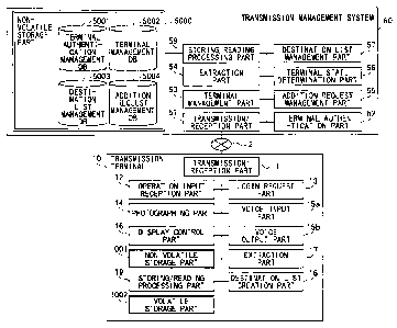
<<Functional Configuration of First Embodiment>>
Next, a functional configuration of the first
embodiment will be described. FIG. 7 shows a functional
block diagram of the terminal 10 and the transmission
management system 50 included in the transmission system
1 according to the first embodiment. In FIG. 7, the
terminal 10 and the transmission management system 50 are
connected together by the communication network 2 in such
a manner that data transmission can be mutually carried out.
CA 02817356 2013-05-08
WO 2012/074124 PCT/JP2011/078008
28
Further, the program providing system 90 shown in FIG. 1
is omitted in FIG. 7 because the program providing system
90 does not directly relate to communication for a TV
conference.
<Functional Configuration of Terminal>
The terminal 10 includes a
transmission/reception part 11, an operation input
reception part 12, a login request part 13, a photographing
part 14, a voice input part 15a, a voice output part 15b,
a display control part 16, an extraction part 17, a .
destination list creation part 18 and a storing/reading
processing part 19. The respective parts correspond to
functions or functioning parts realized as a result of the
respective ones of elements/components shown in FIG. 5
operating according to instructions given by the CPU 101
that operates according to the program for the terminal
developed on the RAM 103 from the flash memory 104.
Further, the terminal 10 has a volatile storage
part 1002 provided by the RAM 103 shown in FIG. 5 and a
non-volatile storage part 1001 provided by the flash memory
104.
(Detailed Functional Configuration of Terminal)
With reference to FIGS. 5 and 7, the functional
CA 02817356 2013-05-08
WO 2012/074124 PCT/JP2011/078008
29
configuration of each of the parts of the terminal 10 will
be described in detail. Further, below, along with
describing the respective functional configurations of the
parts of the terminal 10, relationships with main
elements/components, from among those shown in FIG. 5, used
for realizing the respective functional configurations of
the parts of the terminal 10 will be also described.
The transmission/reception part 11 of the
terminal 10 is realized by instructions from the CPU 101
shown in FIG. 5 and the network I/F 111 shown in FIG. 5,
and carries out transmission and reception of various sorts
of data (or information) with another terminal, apparatus
or system via the communication network 2. The
transmission/reception part 11 starts reception of
respective state information indicating states of
respective terminals as candidates for a destination from
the transmission management system 50 before starting a
telephone call with the desired destination terminal. It
is noted that the state information indicates not only an
operating state (on-line or off-line) of each terminal but
also a detailed state of whether on telephone call further
when on-line, whether the user is leaving his or her seat,
or so. Further, the state information indicates various
states including not only the operating state of each
terminal but also whether the cable 120c has been removed
=
CA 02817356 2013-05-08
WO 2012/074124 PCT/JP2011/078008
from the terminal 10, whether the terminal 10 has been set
to output voice but not output an image, or output no voice
(MUTE), and so forth.
The operation input reception part 12 is realized
5 by instructions from the CPU 101 shown in FIG. 5 and the
operating buttons 108 and the power supply switch 109, and
receives various sorts of input operations carried out by
the user. For example, when the user turns on the power
supply switch 109, the operation input reception part 12
10 shown in FIG. 7 turns on the power supply in the terminal
10 by receiving the user's operation of turning on the power
supply switch 109.
The login request part 13 is realized by
instructions from. the CPU 101, and automatically transmits
15 login request information indicating to request login and
an IP address of the requested terminal at the current time
to the transmission management system 50 via the
communication network 2 from the transmission/reception
part 11 in response to receiving the user's operation of
20 turning on the power supply switch 109. Further, when the
user turns off the power supply switch 109, the
transmission/reception part 11 transmits the state
information to turn off the power supply to the transmission
management system 50, and after that, the operation input
25 reception part 12 completely turns off the power supply in
CA 02817356 2013-05-08
WO 2012/074124 PCT/JP2011/078008
31
the terminal 10. Thus, the transmission management system
50 can understand that the terminal 10 is changing its state
from the power turned on (power supply ON) to the power
turned off (power supply OFF).
The photographing part 14 is realized by
instructions from the CPU 101, and the camera 112 and the
image sensor I/F 113 shown in FIG. 5, and photographs an
object and outputs image data thus obtained from the
photographing.
The voice input part 15a is realized by
instructions from the CPU 101 and the voice input/output
I/F 116 shown in FIG. 5, and inputs voice data expressed
by a voice signal when a voice of the user is converted into
the voice signal by the microphone 114. The voice output
part 15b is realized by instructions from the CPU 101 and
the voice input/output I/F 116, and outputs a voice signal
expressing voice data to the speaker 115 and causes the
speaker 115 to output a voice.
The display control part 16 is realized by
instructions from the CPU 101 and the display I/F 117 shown
in FIG. 5, and carries out control to transmit image data
to the display device 120 provided in the outside.
The extraction part 17 is realized by
instructions from the CPU 101, and extracts various sorts
of data (or information) from a volatile storage part 1002.
CA 02817356 2013-05-08
WO 2012/074124 PCT/JP2011/078008
32
The destination list creation part 18 creates and
updates a destination list where, as shown in FIG. 13, states
of destination candidates are indicated by icons, based on
destination list information and state information of
terminals 10 as destination candidates received from the
transmission management system 50.
The storing/reading processing part 19 is
realized by instructions from the CPU 101 and the SSD 105
shown in FIG. 5, stores various sorts of data in a
non-volatile storage part 1001, and reads various sorts of
data stored in the non-volatile storage part 1001. In the
non-volatile storage part 1001, terminal IDs
(identifications) as examples of identification
information for identifying the terminals 10, respectively,
passwords and so forth, are stored. Further, the
storing/reading processing part 19 also stores various
sorts of data in the volatile storage part 1002, and reads
various sorts of data stored in the volatile storage part
1002. In the volatile storage part 1002, image data and
voice data received when a telephone call is carried out
with a destination terminal 10 are stored in an overwriting
manner each time of receiving. There, an image is displayed
on the display device 120 from the image data before being
overwritten, and voice audio is output from the speaker 115
from the voice data before being overwritten.
CA 02817356 2013-05-08
WO 2012/074124 PCT/JP2011/078008
33
It is noted that the terminal IDs and relay
apparatus IDs described later according to the first
embodiment indicate identification information such as a
language, a character/letter, a sign or various sorts of
marks used for uniquely identifying the respective
terminals 10 and relay apparatuses 30. Further, each of
the terminal IDs and the relay apparatus IDs may be
identification information that is a combination of at
least two of the above-mentioned language,
character/letter, sign and various sorts of marks.
<Functional Configuration of Transmission Management
System>
The transmission management system 50 includes
a transmission/reception part 51, a terminal
authentication part 52, a terminal management part 53, an
extraction part 54, an addition request management part 55,
a terminal state determination part 56, a destination list
management part 57, a storing/reading processing part 59 _
and a delay time management part 60. These respective parts
correspond to functions or functioning parts realized as
a result of the respective elements/components shown in FIG.
6 operating according to instructions given by the CPU 201
that operates according to the program for transmission
management loaded in the RAM 203 from the HD 204. Further,
CA 02817356 2013-05-08
WO 2012/074124 PCT/JP2011/078008
34
the transmission management system 50 has a non-volatile
storage part 5000 where various sorts of data (or
information) are maintained even after the power supply in
the transmission management system 50 is turned off. The
non-volatile storage part 5000 comprises the HD 204 shown
in FIG. 6. Further, in the non-volatile storage part 5000,
data of a destination list frame shown in FIG. 13 (i.e.,
data of a destination list frame shown in FIG. 13, not
including icons indicating specific operating states,
terminal IDs and terminal names) is stored.
(Terminal Authentication Management Table)
Further, in the non-volatile storage part 5000,
a terminal authentication management DE 5001 including a
terminal authentication management table such as that shown
in FIG. 8 is stored. In the terminal authentication
management table, respective passwords are associated with
the terminal IDs of the terminals 10 managed by the
transmission management system 50 and are managed. For
example, in the terminal authentication management table
shown in FIG. 8, it is indicated that the terminal ID of
the terminal 10aa is "Olaa", and the password is "aaaa".
(Terminal Management Table)
Further, in the non-volatile storage part 5000,
CA 02817356 2013-05-08
WO 2012/074124 PCT/JP2011/078008
a terminal management DB 5002 including the terminal
management table such as that shown in FIG. 9 is stored.
In the terminal management table, for the terminal ID of
each of the terminals 10, a destination name (i.e., terminal
5 name) for a case where the terminal 10 acts as a destination,
the operating state of the terminal 10, the reception date
and time when login request information (described later)
has been received by the transmission management system 50,
and the IP address of the terminal 10 are associated with
10 each other and are managed. For example, in the terminal
management table shown in FIG. 9, it is indicated that the
terminal 10aa having the terminal ID "Olaa" has the
destination name "JAPAN TOKYO OFFICE AA TERMINAL", the
operating state "on-line (transmission possible)", the
15 reception date and time when the login request information
has been received in the transmission management system 50
is "November 10, 2009, 13:40", and the IP address of the
terminal 10aa is "1.2.1.3".
20 (Destination List Management Table)
Further, in the non-volatile storage part 5000,
a destination list management DB 5003 including the
destination list management table such as that shown in FIG.
10 is stored. In the destination list management table,
25 for the terminal ID of a request source terminal which
CA 02817356 2013-05-08
WO 2012/074124 PCT/JP2011/078008
36
requests to start a telephone call in a TV conference, all
of the terminal IDs of the destination terminals registered
as candidates fora destination terminal are associated and
are managed. For example, in the destination list
management table shown in FIG. 10, it is indicated that the
candidates for a destination terminal for which the request
source terminal (terminal 10aa) can request to start a
telephone call in a TV conference are the terminal 10ab
having the terminal ID "Olab, the terminal 10ba having the
terminal ID "Olba", the terminal lObb having the terminal
ID "Olbb" and so forth. The candidates for a destination
terminal are updated as a result of addition or deletion
according to a request of addition or deletion from any
request source terminal to the transmission management
system 50.
Further, in the destination list management
table (the destination list management DB 5003, see FIG.
10), not only the terminal IDs of the destination terminals
registered as candidates for a destination terminal, but
also the destination names managed in the terminal
management table (the terminal management DB 5002, see FIG.
9) for the respective terminal IDs may be managed as being
associated with the respective terminal IDs.
(Addition Request Management Table)
CA 02817356 2013-05-08
WO 2012/074124 PCT/JP2011/078008
37
Further, in the non-volatile storage part 5000,
an addition request management DB 5004 including an
addition request management table such as that shown in FIG.
11 is stored. In the addition request management table,
a terminal ID of a terminal (hereinafter, referred to as
"request source terminal" the same as the above-described
start request source terminal for a telephone call) having
requested to add a destination candidate and a terminal ID
of a terminal which is thus requested to be the destination
candidate (hereinafter, referred to as "request target
terminal") are associated with one another and managed.
Thereby, it is possible to manage which terminal has
requested to add which terminal as a destination terminal.
It is noted that the destination list management table and
the addition request management table have the terminal IDs
of the request source terminals common therebetween, and
therefore, it is possible to integrate these two tables into
a single table.
(Detailed Functional Configuration of Transmission
Management System)
Next, the functional configuration of each of the
parts included in the transmission management system 50
will be described in detail. It is noted that below along
with describing the respective functional configurations
CA 02817356 2013-05-08
WO 2012/074124 PCT/JP2011/078008
38
of the parts of the transmission management system 50,
relationships with main elements/components, from among
those shown in FIG. 6, used for realizing the respective
functional configurations of the parts of the transmission
management system 50 will be also described.
The -transmission/reception part 51 shown in FIG.
7 is realized by instructions from the CPU 201 shown in FIG.
6 and the network I/F 209 shown in FIG. 6, and carries out
transmission and reception of various sorts of data
(information) with another set of equipment such as a
terminal 10, a relay apparatus 30 or a system 90 or 100 via
the communication network 2.
The terminal authentication part 52 is realized
by instructions from the CPU 201, searches the terminal
authentication management DB 5001 in the non-volatile
storage part 5000 using the terminal ID and the password
included in the login request information received via the
transmission/reception part 51 as search keys, and carries
out authentication of the terminal 10 by determining
whether the same set of the terminal ID and password is
managed in the terminal authentication management DB5001.
The terminal management part 53 is realized by
instructions from the CPU 201, and for the purpose of
managing the operating state of a request source terminal
which has requested to login, stores the terminal ID of the
CA 02817356 2013-05-08
WO 2012/074124 PCT/JP2011/078008
39
request source terminal, the operating state of the request
source terminal, the reception date and time when the login
request information has been received in the transmission
management system 50 and the IP address of the request source
terminal in the terminal management DB 5002 (see FIG. 9)
it a manner of associating them with each other and manages
them. Further, the terminal management part 53 changes the
operating state indicating on-line in the terminal
management DB 5002 (see FIG. 9) into off-line based on the
state information indicating that power supply will be
turned off sent from a terminal 10 in response to the user
of the terminal 10 turning off the power supply switch 109
of the terminal 10.
The extraction part 54 is realized by
instructions from the CPU 201 shown in FIG. 6, searches the
destination list management DB 5003 (see FIG. 10) using the
terminal ID of a request source terminal which has requested
to login as a search key, reads the terminal IDs of
candidates for a destination terminal which can carry out
a telephone call with the request source terminal, and
extracts the terminal IDs. Further, the extraction part
54 searches the destination list management DB 5003 (see
FIG. 10) using the terminal ID of a request source terminal
which has requested to login as a search key, and extracts
also the terminal IDs of the other request source terminals
CA 02817356 2013-05-08
WO 2012/074124 PCT/JP2011/078008
which have registered the terminal ID of the request source
terminal as a candidate for a destination terminal.
Further, the extraction part 54 searches the terminal
management DB 5002 (see FIG. 9) using the terminal IDs of
5 candidates for a destination terminal thus extracted by the
extraction part 54 as search keys, and reads the operating
state for each of the terminal IDs thus extracted by the
extraction part 54. Thereby, the extraction part 54 can
obtain the operating states of the candidates for. a
10 destination terminal which can carry out a telephone call
with the request source terminal having requested to login.
Further, the extraction part 54 searches the terminal
management DB 5002 (see FIG. 9) using the terminal ID of
the request source terminal having requested to login, and
15 obtains the operating state of the request source terminal
having requested to login.
The addition request management part 55 is
realized by instructions given by the CPU 201 shown in FIG.
6, newly stores the terminal ID of the request source
20 terminal and the terminal ID of the request target terminal
in the addition request management DB 5004 (see FIG. 11)
for each of the records, and manages them. Further, the
addition request management part 55 deletes the terminal
ID of the request source terminal and the terminal ID of
25 the request target terminal in the addition request
CA 02817356 2013-05-08
WO 2012/074124 PCT/JP2011/078008
41
management DB 5004 (see FIG. 11) for each of the records.
The terminal state determination part 56 is
realized by instructions given by the CPU 201 shown in FIG.
6, searches the terminal management DB 5002 (see FIG. 9)
using a terminal ID or a destination name as a search key,
and determines the corresponding operating state.
The destination list management part 57 is
realized by instructions given by the CPU 201 shown in FIG.
6, and adds or deletes the terminal ID of a destination
terminal for each of the terminal IDs in the destination
list management DB 5003 (see FIG. 10). Further, the
destination list management part 57 manages, for the
terminal ID of the request source terminal in the
destination list management DB 5003 (see FIG. 10) the same
as the terminal ID of the request source terminal managed
in the addition request management DB 5004 (see FIG. 11),
the terminal ID of the request target terminal managed in
association with the terminal ID of the request source
terminal in the addition request management DB 5004 (see
FIG. 11), as a terminal ID of a destination terminal
additionally in a manner of associating them.
The storing/reading processing part 59 is
realized by instructions from the CPU 201 and by the HDD
205 shown in FIG. 6, stores various sorts of data in the
non-volatile storage part 5000 and reads various sorts of
CA 02817356 2013-05-08
WO 2012/074124 PCT/JP2011/078008
42
data stored in the non-volatile storage part 5000.
<<Processing/Operations of First Embodiment>>
Next, with reference to FIGS. 12 through 18,
processes carried out in the first embodiment will be
described. First, with reference to FIGS. 12 and 13, a
process of transmission/reception of various sorts of
management information at a preparation stage before
starting a telephone call between the terminal 10aa and the
terminal 10db will be described. FIG. 12 is a sequence
diagram showing a process of a preparation step for starting
a telephone call between the terminals. FIG. 13 shows a
concept of the destination list. It is noted that in FIG.
12, various sorts of management information are transmitted
and received by the management information session "sei"
shown in FIG. 2.
First, when the user turns on the power supply
switch 109 shown in FIG. 5, the operation input reception
part 12 shown in FIG. 7 receives the power supply turning
on operation, and turns on the power supply in the terminal
10aa (step S21). Then, in response to the reception of the
power supply turning on operation, the login request part
13 automatically transmits login request information
indicating a login request to the transmission management
system 50 via the communication network 2 from the
CA 02817356 2013-05-08
WO 2012/074124 PCT/JP2011/078008
43
transmission/reception part 11 (step S22). The login
request information includes the terminal ID for
identifying the own terminal (terminal 10aa) as the request
source and the password. The terminal ID and password are
data having been read out from the non-volatile storage part
1001 via the storing/reading processing part 19 and having
been sent to the transmission/reception processing part 11.
It is noted that when the login request information is
transmitted to the transmission management system 50 from
the terminal 10aa, the transmission management system 50
that has received the login request information can obtain
the IP address of the terminal 10aa that has sent the login
request information.
Next, the terminal authentication part 52 in the
transmission management system 50 searches the terminal
authentication management DB 5001 (see FIG. 8) of the
non-volatile storage part 5000 using the terminal ID and
the password included in the login request information
having been received from the transmission/reception part
51 as search keys, determines whether the same terminal ID
and password are managed in the terminal authentication
management DB 5001, and thus, carries out authentication
of the terminal 10aa by determining whether the same
terminal ID and password are managed (step S23). Ina case
where it has been determined by the terminal authentication
CA 02817356 2013-05-08
WO 2012/074124 PCT/JP2011/078008
44
part 52 that the login request is one sent from the terminal
10aa having proper use authority since the same terminal
ID and password are managed, the state management part 53
stores, for the record indicated by the terminal ID and the
destination name of the terminal 10aa, the operating state
thereof, the reception date and time when the
above-mentioned login request information has been
received, and the IF address of the terminal 10aa in the
terminal management DB 5002 (see FIG. 9) in a manner of
associating them with each other (step S24). Thereby, in
the terminal management table shown in FIG. 9, the operating
state "on-line", the reception date and time
"2009.11.10.13:40" =and the IP address "1.2.1.3" are
associated with the terminal ID "Olaa" and are managed.
Then, the transmission/reception part 51 of the
transmission management system 50 transmits authentication
result information indicating the result of the
authentication obtained by the terminal authentication
part 52 to the request source terminal (terminal 10aa),
having carried out the above-mentioned login request, via
the communication network 2 (step S25) . Below, description
will be carried out continuously supposing a case where the
terminal authentication part 52 has determined that the
terminal having carried out the above-mentioned login
request has the proper use authority.
CA 02817356 2013-05-08
WO 2012/074124 PCT/JP2011/078008
When receiving the authentication result
information indicating the result of being determined as
having the proper use authority, the
transmission/reception part 11 of the request source
5 terminal (terminal 10aa) transmits destination list
request information requesting a destination list to the
transmission management system 50 via the communication
network 2 (step S26). Thereby, the transmission/reception
part 51 of the transmission management system 50 receives
10 the destination list request information.
Next, the extraction part 54 of the transmission
management system 50 searches the destination list
management DB 5003 (see FIG. 10) using the terminal ID "Olaa"
of the request source terminal (terminal 10aa) having
15 carried out the login request as a search key, and extracts
the terminal IDs of candidates for a destination terminal
which can carryout a telephone call with the request source
terminal (terminal 10aa), and also reads the destination
names corresponding to the terminal IDs from the terminal
20 management DB 5002 (see FIG. 9) (step S27). In this regard,
in the case where not only the terminal IDs but also the
destination names associated with the respective terminal
IDs are managed in the destination list management table
(the destination list management DB 5003 (see FIG. 10) )
25 as mentioned above, the destination names corresponding to
CA 02817356 2013-05-08
WO 2012/074124 PCT/JP2011/078008
46
the terminal IDs may be read from the destination list
management table (the destination list management DB 5003)
instead of the terminal management table (the terminal
management DB 5002 (see FIG. 9)) in step S27. Here, the
terminal IDs ("Olab", "Olba", "Olbb", ...) of destination
terminals (terminals 10ab, 10ba, lObb, ...) corresponding
to the terminal ID "Olaa" of the request source terminal
(terminal 10aa), and further, the terminal names
corresponding thereto ("Japan Tokyo office AB terminal",
"Japan Osaka office BA terminal", "Japan Osaka office BB
terminal", ...) are extracted.
Next, the transmission/reception part 51 of the
transmission management system 50 reads the data of the
destination list frame from the storage part 6000 via the
storing/reading processing part 59 (step S28), and also,
transmits "destination list information (destination list
frame, terminal IDs and destination names)" including the
destination list frame, the terminal IDs and the
destination names thus extracted by the extraction part 54
to the request source teiminal (terminal 10aa) (step S29).
Thereby, in the request source terminal (terminal 10aa),
the transmission/reception part 11 receives the
destination list information, and the storing/reading
processing part 19 stores the destination list information
in the volatile storage part 1002 (step S30).
CA 02817356 2013-05-08
WO 2012/074124 PCT/JP2011/078008
47
Thus, according to the first embodiment, the
terminals 10 do not manage the destination list information
but the transmission management system 50 manages the
destination list information for all the terminals 10 in
a unifying manner. Thereby, even in a case where a new
terminal 10 comes to be included in the transmission system,
in a case where a terminal 10 of a new type comes to be
included instead of an existing terminal 10 or in a case
where the appearance or such of the destination list frame
is to be changed, the transmission management system 50
deals with the matter, and thus, it is possible to eliminate
the work of changing the destination list to be carried out
by the terminals 10.
Further, the extraction part 54 in the
transmission management system 50 searches the terminal
management DB 5002 (see FIG. 9) using the terminal IDs
("Olab", "Olba", "Olbb", ...) of the candidates for a
destination terminal extracted by the extraction part 54
as search keys, reads the respective operating states
corresponding to the above-mentioned respective terminal
IDs extracted by the extraction part 54, and obtains the
respective operating states of the terminals (10ab, 10ba,
lObb, ...) as the destination candidates (step S31).
Next, the transmission/reception part 51
transmits a set of "terminal operating state information"
CA 02817356 2013-05-08
WO 2012/074124 PCT/JP2011/078008
48
including the terminal ID "Olab" extracted as one of the
candidates for a destination terminal by the extraction
part 54 in step S27 and the operating state "on-line
(telephone call possible)" of the corresponding
destination terminal (terminal 10ab) to the request source
terminal (terminal 10aa) via the communication network 2
(step S32). Further, also in step S32, the
transmission/reception part 51 transmits another set of
"terminal operating state information" including the
terminal ID "Olba" extracted as another of the candidates
for a destination terminal by the extraction part 54 in step
S27 and the operating state "on-line (temporarily
interrupted)" of the corresponding destination terminal
(terminal 10ba) to the request source terminal (terminal
10aa) via the communication network 2. In the same way,
in step S32, the transmission/reception part 51 transmits
respective sets of "terminal operating state information"
for all of the remaining terminals extracted as the
candidates for a destination terminal by the extraction
part 54 in step S27 to the request source terminal (terminal
10aa) via the communication network 2, separately.
Next, the storing/reading processing part 19 in
the request source terminal (terminal 10aa) stores the
respective sets of the terminal operating state information
received from the transmission management system 50 in the
CA 02817356 2013-05-08
WO 2012/074124 PCT/JP2011/078008
49
volatile storage part 1002, in sequence (step S33).
Thereby, the request source terminal (terminal 10aa) can
obtain the respective operating states of the respective
terminals 10ab, ... at the current time which are the
candidates for a destination terminal which can carry out
a telephone call with the request source terminal (terminal
10aa).
Next, the destination list creation part 18 of
the request source terminal (terminal 10aa) creates a
destination list on which the states of the terminals 10
as the destination candidates are reflected based on the
destination list information and the terminal operating
state information stored in the volatile storage part 1002.
Further, the display control part 16 controls timing of
displaying the destination list on the display device 120
shown in FIG. 5 (step S34). It is noted in the destination
list shown in FIG. 13, icons Id, Ic2, Ic3 and Ic4 represent
the respective operating states of the terminals, i.e.,
from the top, "on-line (transmission possible)" (Id),
"off-line" (Ic2), "on-line (transmission possible)" (Ic3)
and "on-line (on telephone call)" ( Ic4 ) . In a TV conference
according to the first embodiment, "transmission possible"
means "telephone call possible".
On the other hand, the extraction part 54 of the
transmission management system 50 searches the destination
CA 02817356 2013-05-08
WO 2012/074124 PCT/JP2011/078008
list management DB 5003 (see FIG. 10) using the terminal
ID "Olaa" of the request source terminal (terminal 10aa)
having carried out the login request as a search key, and
extracts the terminal IDs of the other request source
5 terminals which have registered the above-mentioned
request source terminal (terminal 10aa) as a candidate for
a destination terminal (step S35) . In the destination list
table shown in FIG. 10, the terminal IDs of the other request
source terminals to be extracted are "01ab", "Olba" and
10 "Oldb".
Next, the extraction part 54 of the transmission
management system 50 searches the terminal management DB
5002 (see FIG. 9) using the terminal ID "Olaa" of the request
source terminal (terminal 10aa) having carried out the
15 above-mentioned login request, and obtains the operating
state of the request source terminal (terminal 10aa) having
carried out the login request (step S36) .
Next, the transmission/reception part 51
transmits "terminal state information" including the
20 terminal ID "Olaa" of the request source terminal (terminal
10aa) and the operating state "on-line" obtained in step
S36 to the terminals 10ba and 10db which have the operating
state of "on-line" in the terminal management DB 5002 (see
FIG. 9) among the terminals 10ab, 10ba and 10db having the
25 terminal IDs Olab, Olba and Oldb extracted in step S35 (step
CA 02817356 2013-05-08
WO 2012/074124 PCT/JP2011/078008
51
S37-1, S37-2). It is noted that when the
transmission/reception part 51 is to transmit the terminal
state information to the terminals 10ba and 10db, the
transmission/reception part 51 reads the IP addresses of
these terminals managed in the terminal management table
shown in FIG. 9 based on the respective terminal IDs ("Olba"
and "Oldb"). Thereby, it is possible to inform the
respective destination terminals (terminals 10ba and 10db)
which can carry out a telephone call with the request source
terminal (terminal 10aa) having carried out the login
request as the destination, of the terminal ID "Olaa", and
the operating state "on-line" of the request source
terminal (terminal 10aa) having carried out the
above-mentioned login request.
On the other hand, also at each of the other
terminals 10, the same as the above-mentioned step S21,
when the user turns on the power supply switch 109 shown
in FIG. 6, the operation input reception part 12 shown in
FIG. 7 receives the power supply turning on operation, and
the processes the same as those of steps S22 through S38-1
and S38-2 mentioned above are carried out. Therefore, the
description therefor will be omitted.
Next, using FIGS. 14 through 18, a process of
adding a destination candidate will be described. As one
example, a case will be supposed where the request source
CA 02817356 2013-05-08
WO 2012/074124 PCT/JP2011/078008
52
terminal (terminal 10aa) requests to add a request target
terminal (terminal 10dc) to the own destination list. It
is noted that FIG. 14 is a sequence diagram showing a process
of adding a destination candidate. FIG. 15 shows a concept
of an addition request reception screen page. FIG. 16 is
a flowchart showing a process of approval and rejection.
FIG. 17 shows a concept of an addition approval request
screen page. FIG. 18 shows a concept of an addition
completion screen page.
First, the user "a" of the request source
terminal (terminal 10aa ) operates the operating button 108,
and presses an "add destination" button displayed at a
bottom right of the destination list shown in FIG. 13, and
thereby, the operation input reception part 12 receives
this pressing operation, and the display control part 16
displays an addition request reception screen page, data
of which is stored in the volatile storage part 1002, on
the display device 120aa. Thus, a process for receiving
a request to add a destination candidate (step S41) can be
carried out. The addition request reception screen page
Scl is thus displayed, as shown in FIG. 15, over the
destination list.
Next, when the user "a" operates the operating
button 108, inputs the terminal ID or the terminal name of
the terminal (in this example, the terminal ID "Oldc") which
CA 02817356 2013-05-08
WO 2012/074124 PCT/JP2011/078008
53
the user intends to add as a destination candidate on the
addition request reception screen page Scl, and presses a
"transmit addition request" button., the operation input
reception part 12 receives this input by the user "a", and
the transmission/reception part 11 transmits addition
request information indicating the request to add the
destination candidate to the transmission management
system. 50 via the communication network 2 (step S42). This
addition request information includes terminal ID "Olaa"
of the request source terminal for identifying the request
source terminal (terminal 10aa), and the terminal ID "Oldc"
of the request target terminal for identifying the request
target terminal (terminal 10dc). Thereby, the
transmission/reception part 51 of the transmission
management system 50 receives the addition request
information.
Next, in the transmission management system 50,
the addition request management part 55 stores the received =
terminal ID "Olaa" of the request source terminal at the
terminal ID field for a request source terminal on a new
record of the addition request management DB5004 (see FIG.
11) and manages it, and also, additionally stores the
terminal 1p "Oldc" of the request target terminal at the
terminal ID field for a request target terminal on the new
record and manages it (the first line in the addition request
CA 02817356 2013-05-08
WO 2012/074124 PCT/JP2011/078008
54
management table of FIG. 11) (step S43). It is noted that
in FIG. 11, with respect to the same terminal ID "Olab",
the terminal IDs of the different request target terminals
("Olca", "Olda") are managed at separate records,
respectively. However, this configuration is not limiting,
and instead, it is also possible to manage the terminal IDs
("Olca", "Olda") of the different request target terminals
with respect to the terminal ID "Olab" of the same request
source terminal on the same record.
Next, the terminal state determination part 56
searches the terminal management DB5002 (see FIG. 9) based
on the terminal ID "Oldc" of the request target terminal,
and determines the corresponding operating state (step S44) .
In a case where the terminal state determination part 56
has determined that the corresponding operating state is
on-line and telephone call (transmission) has not been
started, the transmission/reception part 51 then transmits
addition approval request information indicating a request
to approve the above-mentioned addition request, to the
request target terminal (terminal 10dc) (step S45). This
addition approval request information includes the
terminal ID "Olaa" of the request source terminal. Thereby,
the transmission/reception part 11 of the request target
terminal (terminal 10dc) receives the addition approval
request information.
CA 02817356 2013-05-08
WO 2012/074124 PCT/JP2011/078008
Next, the request target terminal (terminal
10dc) carries out, with respect to the addition request,
a process of approval, rejection or deferring (step S46).
The step S46 will be described in detail using FIGS. 16 and
5 17.
First, when the addition approval request
information is received by the request target terminal
(terminal 10dc), the storing/reading processing part 19
stores the received addition approval request information
10 in the volatile storage part 1002 (step S46-1 in FIG. 16).
It is noted that in a case where plural sets of the addition
approval request information are transmitted one after
another, these are stored in the volatile storage part 1002
one after another.
15 Next, the extraction part 17 tries to extract the
terminal ID of the request source terminal included in the
addition approval request information from the volatile
storage part 1002 (step S46-2). It is noted that in a case
where plural sets of the addition approval request
20 information are stored, the terminal IDs included in the
respective sets of the addition approval request
information are extracted one by one.
Then, in a case where the terminal ID of the
request source terminal has been extracted (step S46-2 and
25 step
S46-3 YES), the display control part 16 displays , as
CA 02817356 2013-05-08
WO 2012/074124 PCT/JP2011/078008
56
shown in FIG. 17, an addition approval request screen page
Sc2 on the display device 120dc (step S46-4) . This addition
approval request screen page Sc2 includes the terminal ID
or the name of the request source terminal. Then, the user
"d" of the request target terminal (terminal 10dc) presses
the "yes" button indicated on the addition approval request
screen page Sc2 in a case where the user "d" of the request
target terminal (terminal 10dc ) approves the request target
terminal (terminal 10dc) being registered in the
destination list of the request source terminal (terminal
10aa). The user "d" of the request target terminal
(terminal 10dc) presses the "no" button indicated on the
addition approval request screen page Sc2 in a case where
the user "d" does not approve the request target terminal
being registered in the destination list of the request
source terminal (terminal 10aa). The user "d" of the
request target terminal (terminal 10dc) presses the
"cancel" button indicated on the addition approval request
screen page Sc2 in a case where the user "d" defers
determining whether to approve the own terminal being
registered in the destination list of the request source
terminal (terminal 10aa). It is noted that in a case where
the terminal name of the request source terminal is
displayed as shown in FIG. 17, the addition approval request
information transmitted in step S45 includes, in addition
CA 02817356 2013-05-08
WO 2012/074124 PCT/JP2011/078008
57
to the terminal ID of the request source terminal, the
terminal name of the request source terminal. Further, in
this case, the terminal name of the request source terminal
is extracted when the operating state of the request source
terminal is determined in step S44.
Next, when the user "d" presses any one of the
"yes", "no" and "cancel" buttons on the addition approval
request screen page Sc2, the operation input reception part
12 receives the instruction of the any one of "yes", "no"
and "cancel" (step S46-5) . Then, further, step S46-2 is
returned to, extraction of the terminal ID (s) of the
remaining request source terminal (s) stored in the volatile
storage part 1002 is tried, and thus, the process is repeated
until the terminals ID (s) of all of the request source
terminal (s) has (have) been extracted. When the terminals
ID (s) of all of the request source terminal (s) has (have)
been extracted (step S46-3 NO) , the process of step S46 is
finished.
Next, returning to FIG. 14, the
transmission/reception part 11 of the request target
terminal (terminal 10dc) transmits, to the transmission
management system 50, addition request response
information indicating the response to the request to add
the destination candidate, i.e., the any one of "approval",
"rejection" and "deferring" (step S47) . Thereby, the
CA 02817356 2013-05-08
WO 2012/074124 PCT/JP2011/078008
58
transmission/reception part 51 of the transmission
management system 50 receives the addition request response
information. Here, a case will be supposed where the
response to the request to add the destination candidate
indicates "approval".
Next, the destination list management part 57
associates the terminal ID "Oldc" of the request target
terminal, associated with the terminal ID "Olaa" of the
request source terminal in the addition request management
DB 5004 (see FIG. 11), with the terminal ID "Olaa" of the
request source terminal in the destination list management
DB (see FIG. 10), the same as the terminal ID "Olaa" of the
request source terminal included in the addition request
management DB 5004 (see FIG. 11), and additionally manages
the terminal ID "Oldc" of the request target terminal (step
S48).
In a case where the response to the request to
add the destination candidate indicates "rejection", in
step S48, the addition request management part 55 deletes
the record of the terminal ID "Oldc" of the rejected request
target terminal from the addition request management DB
5004 (see FIG. 11). In a case where the response to the
request to add the destination candidate indicates
"deferring", in step S48, the addition request management
part 55 does not carry out such additional management, and
CA 02817356 2013-05-08
WO 2012/074124 PCT/JP2011/078008
59
the destination list management part 57 does not delete the
corresponding record from the addition request management
DB 5004 (see FIG. 11) and leaves the record as it is.
Next, the extraction part 54 searches the
terminal management DB 5002 (see FIG. 9) based on the
terminal ID "Olaa" of the request source terminal and the
terminal ID "Oldc" of the request target terminal, and
extracts the respective sets of information (terminal names
(destination names) and operating states) (step S49) . Then,
the transmission/reception part 51 transmits the
respective sets of addition completion information to the
request source terminal (terminal 10aa) and the request
target terminal (terminal 10dc) (steps S50-1, S50-2). In
the set of addition completion information, from among the
respective sets of addition completion information,
transmitted to the request source terminal (terminal 10aa)
includes a message indicating the completion of the
addition of the destination candidate, and the information
(terminal-ID, terminal name (destination name) and
operating state) of the request target terminal (10dc).
That is, to the request source terminal (terminal 10aa),
only the information (terminal ID, terminal name
(destination name) and operating state), i.e., the part of
the destination list concerning the request target terminal
(terminal 10dc) is transmitted, and thus, all of the
CA 02817356 2013-05-08
WO 2012/074124 PCT/JP2011/078008
destination list is not newly transmitted. On the other
hand, the set of the addition completion information
transmitted to the request target terminal (terminal 10dc)
includes a message indicating the completion of the
5 addition of the destination candidate, and the information
(terminal ID, terminal name (destination name) and
operating state) of the request source terminal (terminal
10aa).
Then, in the request source terminal (terminal
10 10aa) and the request target terminal (terminal 10dc), the
respective display control parts 16 display screen pages
indicating the completion on the respective display devices
(120aa and 120dc) (steps S51-1 and S51-2). FIG. 18 shows
an addition completion screen page Sc3 displayed on the
15 display device 120aa of the request source terminal
(terminal 10aa). When the user "a" of the request source
terminal (terminal 10aa) presses the "OK" button (for
confirmation) on the addition completion screen page Sc3,
the process is finished. As a result of the addition
20 completion screen page Sc3 being thus displayed, the user
"a" of the request source terminal (terminal 10aa ) can early
know that the request to add the destination candidate has
been approved, and thus, can immediately start a TV
conference with the thus-added destination terminal
25 (terminal 10dc).
CA 02817356 2013-05-08
WO 2012/074124 PCT/JP2011/078008
61
It is noted that in the transmission management
system 50, when the processes of steps S50-1 and S50-2 have
been finished, the addition request management part 55
deletes the record of the terminal ID "Oldc" of the approved
request target terminal from the addition request
management DB 5004 (see FIG. 11) , and thus, processing the
request to add the destination candidate is finished (step
S52) .
<<Main Advantageous Effect of First Embodiment>>
Thus, as described above, according to the first
embodiment, before adding a destination candidate to a
destination list, the transmission management system 50
inquires of a terminal 10 which becomes the destination
candidate whether inclusion of the own terminal as the
destination candidate in the destination list is approvable.
Thereby, the user "d" of the terminal 10 which otherwise
becomes the destination candidate can prevent the own
terminal from being included in the destination list of the
other user "a" without approval.
[Second Embodiment]
Next, using FIGS. 19 through 25, a second
embodiment of the present invention will be described. In
a transmission system l' according to the second embodiment,
CA 02817356 2013-05-08
WO 2012/074124 PCT/JP2011/078008
62
in comparison to the transmission system 1 according to the
first embodiment described above, further respective user
PC (Personal Computer) terminals (20a, 20b, 20c and 20d)
are connected with the respective LANs (2a, 2b, 2c and 2d),
and further, a transmission terminal management system 80
is connected with the Internet 2i. The same reference
numerals are given to the same configurations and the same
functions, and the duplicate description therefor will be
omitted.
Further, hereinafter, the user PC terminals (20a,
20b, 20c and 20d) will be referred to as PC (20a, 20b, 20c
and 20d), respectively, and further, any PC thereof will
be referred to as "PC 20".
Further, according to the second embodiment, in
order to solve a problem which may occur when the user lacks
experience of operating the operating buttons 108 and/or
inputting information to the terminal 10 or the user who
is using the PC 20 cannot immediately recognize that the
above-mentioned addition approval request has been given,
necessary operating and inputting information can be
carried out using the PC 20 which the user has used for a
long time instead of the terminal 10. Further, the
transmission terminal management system 80 carries out
communication with the PC 20, and thus, informs the
transmission management system 50 of various requests and
CA 02817356 2013-05-08
WO 2012/074124 PCT/JP2011/078008
63
so forth from the PC 20.
Further, the PC 20 and the transmission terminal
management system 80 have the same external appearances as
those of common server computers, and therefore,
description of external appearances thereof will be omitted.
Further, each of the PC 20 and the transmission terminal
management system 80 has the same hardware configuration
as that of the above-mentioned transmission management
system 50, and therefore, description of hardware
configuration thereof will be omitted.
<<Functional Configuration of Second Embodiment>>
Next, a functional configuration of the second
embodiment will be described. FIG. 20 shows a functional
block diagram of the transmission management system 50 and
the transmission terminal management system 80 included in
the transmission system l' according to the second
embodiment. In FIG. 20, the transmission management system
50 and the transmission terminal management system 80 are
connected together by the communication network 2 in such
a manner that data transmission can be mutually carried out.
Further, the PC 20 shown in FIG. 19 is omitted in FIG. 20
because the PC 20 is an all-purpose PC.
<Functional Configuration of Transmission Terminal
CA 02817356 2013-05-08
WO 2012/074124 PCT/JP2011/078008
64
Management System>
The transmission terminal management system 80
includes a transmission/reception part 81, a terminal
authentication part 82, an extraction part 83, a
destination list creation part 84 and an addition approval
request screen page creation part 85. These respective
parts correspond to functions or functioning parts realized
as a result of the respective elements/components shown in
FIG. 6 operating according to instructions given by the CPU
201 that operates according to the program for the
transmission terminal management system developed on the
RAM 203 from the HD 204.
Further, the transmission terminal management
system 80 includes a storage part 8000 provided by the RAM
203 or HD 204 shown in FIG. 6.
(Detailed Functional Configuration of Transmission
Terminal Management System)
Next, the functional configuration of each of the
parts included in the transmission terminal management
system 80 will be described in detail. It is noted that
below along with describing the respective functional
configurations of the parts of the transmission terminal
management system 80, relationships with main
elements/components, from among those shown in FIG. 6, used
CA 02817356 2013-05-08
WO 2012/074124 PCT/JP2011/078008
for realizing the respective functional configurations of
the parts of the transmission terminal management system
80 will be also described.
The transmission/reception part 81 is realized
5 by instructions from the CPU 201 shown in FIG. 6 and the
network I/F 209 shown in FIG. 6, and carries out transmission
and reception of various sorts of data (information) with
another set of equipment such as a terminal 10, a relay
apparatus 30 or a system 50, 90 or 100 via the communication
10 network 2. Further, the transmission/reception part 81
also has a Web server function and a data processing function
described later.
The terminal authentication part 82 is realized
by instructions from the CPU 201, accesses the transmission
15 management system 50, searches the terminal authentication
management DB 5001 (see FIG. 8) included in the non-volatile
storage part 5000 and carries out authentication as to
whether the terminal 10 of the user of the PC 20 is a proper
terminal for a TV conference by determining whether the same
20 set of terminal ID and password as that of the request source
terminal is managed in the terminal authentication
management DB 5001.
The extraction part 83 is realized by
instructions from the CPU 201 shown in FIG. 6, searches the
25 destination list management DB 5003 (see FIG. 10) in the
CA 02817356 2013-05-08
WO 2012/074124 PCT/JP2011/078008
66
non-volatile storage part 5000 of the transmission
management system 50 using the terminal ID of a request
source terminal, and extracts the terminals ID of the
corresponding destination terminals. Further, the
extraction part 54 searches the addition request management
DB 5004 (see FIG. 11) using the terminal ID of a request
target terminal, and extracts the terminal ID of the
corresponding request source terminal.
The destination list creation part 84 is realized
by instructions given by the CPU 201 shown in FIG. 6, and
creates a HTML (Hyper Text Markup Language) file of a
destination list screen page shown in FIG. 22.
The addition approval request screen page
creation part 85 creates an HTML file of an addition approval
request screen page based on the terminal ID of the request
source terminal extracted by the extraction part 83.
<<Processing/Operations of Second Embodiment>>
Next, using FIGS. 21 through 25, processes
carried out in the second embodiment will be described.
According to the second embodiment, the user "a" of the
request source terminal (terminal 10aa) sends an addition
approval request to the request target terminal (terminal
10dc) via the transmission terminal management system 80
by using the PC 20a instead of the terminal 10aa.
CA 02817356 2013-05-08
WO 2012/074124 PCT/JP2011/078008
67
It is noted that FIG. 21 is a sequence diagram
showing a process of carrying out a request to approve adding
a destination candidate (i.e., an addition approval
request), from a PC 20. FIG. 22 shows a concept of the
destination list. FIG. 23 shows a concept of the addition
request reception screen page.
As shown in FIG. 21, first, the user "a" of the
PC 20a inputs a URL using a Web browser of the PC 20a, and
thereby, the PC 20a accesses a Web application provided by
the transmission terminal management system 80 (step S61).
Thereby, the Web server function of the
transmission/reception part 81 of the transmission
terminal management system 80 discloses a login screen page
to the PC 20a, and thereby, urges the user "a" to input the
terminal ID of the request source terminal (terminal 10aa)
and the password (step S62). When the user "a" inputs the
request source terminal (terminal 10aa) ID and the password
in response thereto, login information including the
request source terminal (terminal 10aa) ID and the password
is transmitted to the transmission terminal management
system 80 from the PC 20a (step S63).
Next, the terminal authentication part 82 of the
transmission management system 80 accesses the
transmission management system 50, searches the terminal
authentication management DE 5001 (see FIG. 8) provided in
CA 02817356 2013-05-08
WO 2012/074124 PCT/JP2011/078008
68
the non-volatile storage part 5000, and determines whether
the terminal 10aa of the user "a" of the PC 20a is a proper
user in the transmission system l' by determining whether
the same set of terminal ID and password as the terminal
ID and the password of the request source terminal are
managed µ( step S64) . Ina case where it has been determined,
in the authentication process, that the request source
terminal is a proper terminal, the extraction part 83 then
searches the destination list management DB 5003 (see FIG.
10) provided in the non-volatile storage part 5000 of the
transmission management system 50 based on the terminal ID
"Olaa" of the request source terminal 10aa, and extracts
the terminal IDs of the corresponding destination terminals
(step S65).
Next, the destination list creation part 84
searches the terminal management DB5002 (see FIG. 9) based
on the terminal IDs extracted in the above-mentioned step
S65, extracts the corresponding terminal names, and thus,
creates a HTML file of a destination list screen page shown
in FIG. 22 (step S66). Then, the Web server function of
the transmission/reception part 81 discloses the
destination list screen page to the PC 20a (step S67). On
the destination list screen page, as shown in FIG. 22, the
destination names of the respective destination terminals,
the terminal IDs of the destination terminals, and an
CA 02817356 2013-05-08
WO 2012/074124 PCT/JP2011/078008
69
operation area for editing the destination name of each
destination terminal on the destination list or deleting
a destination name and a terminal ID of a destination
terminal from the destination list, are displayed. Further,
at a top right corner of the destination list screen page
shown in FIG. 22, an "add destination" button for the user
to press in a case where the user intends to add a destination
candidate is displayed.
Next, when the user "a" of the PC 20a presses the
"add destination" button on the destination list screen
page, the Web browser function of the PC 20a displays an
addition request reception screen page Sc4 such as that
shown in FIG. 23. Thereby, the PC 20a can receive an
addition approval request from the addition request
reception screen page Sc4 (step S68). The addition
approval request screen page Sc4 has the same form as the
addition request reception screen page Scl shown in FIG.
15, and therefore, duplicate description thereof will be
omitted.
Next, when the user "a" inputs the terminal ID
and the terminal name of the request target terminal, which
the user intends to add to the destination list, from the
addition request reception screen page Sc4, and presses a
button of "transmit addition request", the PC 20a transmits
addition approval request information to the transmission
CA 02817356 2013-05-08
WO 2012/074124 PCT/JP2011/078008
terminal management system 80 (step S69). Thereby, the
data processing function of the transmission/reception
part 81 of the transmission terminal management system 80
interprets the above-mentioned operations carried out by
5 the user "a", and transmits addition approval request
information for the destination list to the transmission
management system 50 on behalf of the terminal 10aa (step
S70). Processes thereafter are the same as those of steps
S46 through S52 in FIG. 14, and therefore, duplicate
10 description therefor will be omitted.
Next, using FIGS. 24 and 25, a case will be
described where the user "d" of the request target terminal
10dc sends an addition request response using a PC 20d.
Here, a case will be described where the user "d" determines,
15 immediately after starting up the PC 20d, whether an
addition approval request has been received from another
terminal 10 or another PC 20. It is noted that this case
is one example, and determination as to whether an addition
approval request has been received may be carried out by
20 the user "d", after the user "d" starts up the PC 20d,
periodically or at any time.
It is noted that FIG. 24 shows a sequence diagram
for a case where the user of a request target terminal sends
an addition request response by using a PC 20. FIG. 25 shows
25 a concept of an addition approval request screen page.
CA 02817356 2013-05-08
WO 2012/074124 PCT/JP2011/078008
71
Further, steps S81 through S84 in FIG. 24 are the same
processes as those of steps S61 through S64 in FIG. 21, and
duplicate description therefor will be omitted.
First, the user "d" of the request target
terminal 10dc sends a request to display an addition
approval request screen page to the transmission terminal
management system 80 (step S85). Thereby, in the
transmission terminal management system 80, the extraction
part 83 searches the addition request management DB 5004
(see FIG. 11) based on the terminal ID "Oldc" of the request
target terminal (terminal 10dc), and extracts the terminal
ID "Olaa" of the corresponding request source terminal
(step S86). It is noted that the extraction part 83 may
further search the terminal management DB 5002 (see FIG.
9) based on the terminal ID "Olaa" of the request source
terminal extracted in step S86, and extract the
corresponding destination name (terminal name).
Next, the addition approval request screen page
creation part 85 creates a HTML file of an addition approval
request screen page based on the terminal ID "Olaa" of the
request source terminal (terminal 10aa) extracted in step
S86 (step S87). Then, the Web server function of the
transmission/reception part 81 discloses the addition
approval request screen page such as that shown in FIG. 25
to the PC 20d (step S88).
CA 02817356 2013-05-08
WO 2012/074124 PCT/JP2011/078008
72
Next, when the user "d" selects any one of
"approval", "rejection" and "deferring" from the addition
approval request screen page shown in FIG. 25, addition
request response information indicating the selected one
of "approval", "rejection" and "deferring" is transmitted
to the transmission terminal management system 80 from the
PC 20d (step S89). Then, the data processing function of
the transmission/reception part 81 of the transmission
terminal management system 80 interprets the
above-mentioned operations carried out by the user "d", and
transmits addition request response information to the
transmission management system 50 on behalf of the request
target terminal (terminal 10dc) from the
transmission/reception part 81 (step S90). Processes
thereafter are the same as those of steps S46 through S52
in FIG. 14, and therefore, duplicate description therefor
will be omitted.
<<Main Advantageous Effects of Second Embodiment>>
According to the second embodiment described
above, in addition to the advantageous effects of the first
embodiment, an advantageous effect of solving a problem is
obtained, which problem may occur in a case where the user
"d" of the terminal 10 is not so skilled in operating the
operating buttons 108 of the terminal 10dc and/or a work
CA 02817356 2013-05-08
WO 2012/074124 PCT/JP2011/078008
73
of inputting, or a case where the user "d" who is using the
PC 20d cannot immediately determine that the
above-mentioned addition approval request has been
received.
[Third Embodiment]
Next, using FIGS. 26 and 27, a third embodiment
of the present invention will be described. FIG. 26 shows
a concept of a failure screen page Sc5 at a PC 20 according
to the third embodiment. FIG. 27 shows a concept of a
failure screen page Sc6 at a terminal 10 according to the
third embodiment.
In the above description for the second
embodiment, a case has been described where each business
office is regarded as a virtual person, who operates the
terminal 10 or the PC 20. In the description for the third
embodiment, in order to distinguish between the operator
of the terminal 10 and the operator of the PC 20, it is
supposed that, for example, as a user "d", plural speakers
(participants) belong to the Washington, D.C. office, who
carry out conversations using terminals (10da, 10db,
10dc, ...) or a PC 20d, with other terminals 10, for example.
The speakers are, for example, employees of the user "d".
In the same way, it is supposed that speakers belong to the
user "a" as the Tokyo office, speakers belong to the user
CA 02817356 2013-05-08
WO 2012/074124 PCT/JP2011/078008
74
"b" as the Osaka office, and speakers belong to the user
"c" as the New York office.
Specifically, according to the third embodiment,
in the Washington, D.C. office as the user "d",
approximately at the same time, a speaker dl as an employee
of the user "d" uses the terminal 10dc and a speaker d2 as
another employee of the user "d" uses the PC 20d.
Further, the third embodiment has the same
configuration as the transmission system 1' of the second
embodiment, and also, corresponds to a case where the first
embodiment and the second embodiment are combined. That
is, according to the third embodiment, in state where both
the request target terminal (terminal 10dc) and the PC 20d
have been started up, addition approval request information
is sent to the request target terminal (terminal 10dc) as
in step S45 (FIG. 14) of the first embodiment, and also,
an addition approval request information screen page is
disclosed to the PC 20d as in step S88 (FIG. 24) of the second
embodiment. Then, in such a case, the transmission
management system 50 adopts one of the request target
terminal (terminal 10dc) and the PC 20d, which has carried
out a process of "approval" or "rejection" earlier in
response to the addition approval request for the
destination list.
Therefore, according to the third embodiment,
CA 02817356 2013-05-08
WO 2012/074124 PCT/JP2011/078008
immediately before step S52 shown in FIG. 14, the addition
request management part 55 of the transmission management
system 50 searches the addition request management DB 5004
(see FIG. 11) and determines whether a record exists on which
5 the terminal ID of the request target terminal (10dc) is
managed at the field of a terminal ID of a request target
terminal. For example, even when the PC 20d transmits
addition request response information in step S89 shown in
FIG. 24 after the request target terminal (10dc) first
10 transmits addition request response information
("approval" or "rejection") in step S47 shown in FIG. 14,
the above-mentioned record has been already deleted in step
S52. Therefore, the transmission management system 50
discloses a failure screen page Sc5 such as that shown in
15 FIG. 26 to the PC 20d via the transmission terminal
management system 80. Thereby, the speaker d2 at the PC
20d can determine that another person has already responded
to the addition approval request.
In contrast thereto, even when the request target
20 terminal (10dc) transmits addition request response
information in step S47 shown in FIG. 14 after the PC 20d
first transmits addition request response information
("approval" or "rejection") in step S89 shown in FIG. 24,
the above-mentioned record has been already deleted in step
25 S52. Therefore, the transmission management system 50
CA 02817356 2013-05-08
WO 2012/074124 PCT/JP2011/078008
76
transmits a failure screen page Sc6 such as that shown in
FIG. 27 to the request target terminal (terminal 10dc) .
Thereby, the speaker dl at the request target terminal
(10dc) can determine that another person has already
responded to the addition approval request.
It is noted that in a case where addition request
response information first transmitted indicates
"deferring", the above-mentioned record has not been
deleted. Therefore, in a case where addition request
response information transmitted thereafter indicates
"approval" or "rejection", the addition request response
information transmitted thereafter is adopted.
<Main Advantageous Effects of Third Embodiment>
As described above, according to the third
embodiment, one of a request target terminal 10 and a PC
20, which has earlier processed an addition approval
request by "approval" or "rejection", is preferentially
adopted, and a notification indicating that the process has
failed is sent to the one which has thereafter processed
the addition approval request by "approval" or "rejection".
Thereby, the speaker who has thereafter processed the
addition approval request by "approval" or "rejection" can
determine that another person has already approved or
rejected the addition approval request. Further
CA 02817356 2013-05-08
WO 2012/074124 PCT/JP2011/078008
77
advantageously, the speaker who has first processed the
'addition approval request by "approval" or "rejection" can
be free from being worried that the own processing
("approval" or "rejection") may be thereafter changed by
another.
[Supplement to Embodiments]
It is noted that each of the relay apparatuses
30, the transmission management system 50, the transmission
terminal management system 80, the program providing system
90 and the maintenance system 100 in the first, second and
third embodiments may be realized by a single computer, or
may be realized by plural computers where respective parts
(or functions) are divided and are freely allocated to the
plural computers. Further, in a case where the program
providing system 90 is realized by a single computer, a
program to be transmitted by the program providing system
90 may be transmitted as having been divided into plural
modules, or may be transmitted as not having been divided
into plural modules. Further, in a case where the program
providing system 90 is realized by plural computers,
divided plural modules may be transmitted by the plural
computers, respectively.
Further, recording media storing the program for
the terminal, the program for the relay apparatus, the
CA 02817356 2013-05-08
WO 2012/074124 PCT/JP2011/078008
78
program for transmission management and the program for the
transmission terminal management system, the HD 204 storing
these programs, and the program providing system 90
including the HD 204 are used as program products in a case
where the program for the terminal, the program for the relay
apparatus, the program for transmission management and the
program for the transmission terminal management system are
provided to users or such in the home country or aboard.
Further, in the above-mentioned embodiments, as
an example of the transmission system 1 or l', a case of
a TV conference system has been described. However, it is
not necessary to be limited thereto, and an example of the
transmission system 1 or l' may be a telephone system for
IP (Internet Protocol) telephone, Internet telephone, or
such. Further, the transmission system 1 or l' may be an
automotive navigation system. In this case, one of the
terminals 10 corresponds to an automotive navigation
apparatus mounted in one automobile, and another of the
terminals 10 corresponds to a management terminal or a
management server in a management center which manages the
automotive navigation system, or an automotive navigation
apparatus mounted in another automobile.
Further, the transmission system 1 may be a
communication system for cellular phones. In this case,
the terminals correspond to cellular phones.
CA 02817356 2013-05-08
WO 2012/074124 PCT/JP2011/078008
79
Further, in the above-mentioned embodiments, as
one example of content data, image data as sight data and
voice data as hearing data have been described. However,
it is not necessary to be limited thereto, and others of
the five senses maybe used instead. An example of content
data may be touch data. In this case, a feeling occurring
when a user touches something on the side of one of the
terminals is transmitted to the side of another of the
terminals. Further, content data may be smell data. In
this case, a smell (or odor) occurring on the side of one
of the terminals 10 is transmitted to the side of another
of the terminals 10. Further, content data may be taste
data. In this case, a taste obtained on the side of one
of the terminals 10 is transmitted to the side of another
of the terminals 10.
Further, it may be sufficient that content data
is at least any one of image (sight) data, voice (hearing)
data, touch data, smell data and taste data.
Further, in the above-mentioned embodiments, the
case where the TV conference is conducted by using the
transmission system 1 or l' has been described. However,
it is not necessary to be limited thereto. The transmission
system 1 or l' may be used for a meeting, a common
conversation between family members, friends or such, or
may be used for submitting information in one direction.
CA 02817356 2015-06-05
76311-32
Although this invention has been described in
detail with reference to certain embodiments, variations
and modifications exist within the scope of the
invention as described and defined in the following claims.
5