Note: Descriptions are shown in the official language in which they were submitted.
CA 02817410 2013-06-03
OBTURATOR TIP WITH INSUFFLATION PATHWAY
BACKGROUND
Technical Field
[0002] The present disclosure relates to a surgical access assembly
including an obturator
and a cannula. More particularly, the present disclosure relates to an
obturator including a tip
member with an outer surface having at least one channel for transmitting
fluids thercalong.
Background of Related Art
[0003] Minimally invasive procedures are continually increasing in number
and
variation. Forming a relatively small diameter, temporary pathway to the
target site is a key
feature of most minimally invasive surgical procedures. The most common method
of providing
such a pathway is by inserting an access assembly through the skin. Common
access assemblies
generally include a cannula configured to accommodate a trocar for penetrating
tissue, and an
obturator for dilating and creating a pathway through tissue. Obturators may
be blunt members
that are inserted through the cannula to tunnel a path through tissue and
subsequently to a
selected surgical site.
[0004] Minimally invasive procedures often supply insufflation fluids,
e.g., carbon
dioxide, to a body cavity underlying a layer of tissue such that the layer of
tissue lifts away from
CA 02817410 2013-06-03
underlying tissue or organ structures to create a larger working space. To
this end, a source of
insufflation fluid may be coupled to the cannula such that insufflation fluids
flow distally into a
body cavity. In many procedures, it is desirable to insufflate the body cavity
of a patient while
the obturator is inserted through the cannula. In such an arrangement,
insufflation fluids may be
introduced through an interior portion of the obturator, and exit through an
opening in a distal
portion or tip of the obturator within the working space. Such an arrangement
typically
incorporates an additional source of insufflation fluid coupled with the
obturator, as well as
sealing member within the obturator to inhibit the proximal migration of
insufflation fluids
through the obturator.
SUMMARY
[0005] The present invention, in accordance with various embodiments
thereof; is
directed to a surgical access apparatus, comprising: a cannula including a
housing and a cannula
shaft, the cannula shaft defining an internal lumen; and an obturator
insertable through the
internal lumen of the cannula, the obturator including: an obturator shaft
having a proximal end
and a distal end, and defining a longitudinal axis; and a tip member at the
distal end of the
obturator shaft, the tip member configured to be inserted through tissue and
having an outer
surface, the outer surface defining a channel for insufflation fluid.
[00061 The obturator may be configured to receive within an interior space
thereof an
endoscope, and at least a portion of the tip member, or even the entire tip
member, may permit
light to be transmitted therethrough so as to provide for an optical
obturator. Advantageously,
the channel is not in fluid communication with an interior of the obturator so
as to avoid the need
for a seal between the obturator and the endoscope. En an embodiment, a
distalmost end of the
channel is at or adjacent to a distahnost end of the tip member so as to
enable insufflation fluids
2
CA 02817410 2013-06-03
to begin to be introduced into the body cavity almost immediately upon the
distal tip of the tip
member penetrating through the wall of the body cavity, redwings the
likelihood that an injury
to underlying anatomical structures will occur and further improving patient
safety.
[0007] The outer surface of the tip member may define a plurality of
channels, When the
obturator shaft is disposed in the lumen of the cannula shaft, an annular
space may be defined
between the obturator shaft and the cannula shaft. A portion of the channel
may be in fluid
communication with the annular space. In addition, when the obturator is
inserted in the lumen
of the cannula shaft, at least a portion of the channel may extend distally of
the cannula shaft.
Still further, at least one seal member may be disposed in the cannula. Such a
seal may be
configured to form a fluid-tight seal with the obturator inserted
therethrough. The cannula may
be configured to be coupled to a source of fluid. The channel may be defined
by an open
proximal end, an open distal end, and a pair of opposed walls extending
therebetween.
[0 0 081 In other embodiments, the present invention may be directed to an
obturator
assembly that is configured to be inserted through a cannula. The obturator
assembly may
comprise an obturator shaft having a tip member at a distal end of the
obturator shaft, the tip
member configured to at least one of penetrate and dissect through tissue, the
tip member having
an outer surface that defines a channel, the channel configured to convey
insufflation fluid from
a proximal end of the tip member to a distal end of the tip member.
100091 The obturator may have a hollow interior, and the hollow interior of
the obturator
may be configured to receive an endoscope. At least a portion of the tip
member may permit
light to be transmitted therethrough, and in various embodiments, the entire
tip member may be
light transmissible so as to provide an optical obturator.
3
100101 In other embodiments, the present invention may be directed to a
surgical
access apparatus, comprising a cannula including a housing and a cannula
shaft, the cannula
shaft defining an internal lumen, the cannula having a connection for
receiving insufflation
fluid; and an obturator assembly, the obturator assembly configured to be
inserted through a
cannula so as to define an interstitial space between the cannula and the
obturator assembly,
the interstitial space being in fluid communication with the cannula
connection so as to
convey the insufflation fluid received by the connection, the obturator
assembly including an
obturator shaft having a hollow interior and a tip member at a distal end of
the obturator
shaft, the tip member configured to at least one of penetrate and dissect
through tissue, the tip
member having an outer surface that defines a channel, the channel being in
fluid
communication with the interstitial space to convey the insufflation fluid
from a proximal end
of the tip member to a distal end of the tip member, the channel not being in
fluid
communication with the interior of the obturator.
[0010a] One embodiment of the present invention provides a surgical access
apparatus, comprising: a cannula including a housing and a cannula shaft, the
cannula shaft
defining an internal lumen; and an obturator insertable through the internal
lumen of the
cannula. The obturator includes: an obturator shaft having a proximal end and
a distal end,
and defining a longitudinal axis and a first diameter; and a tip member at the
distal end of the
obturator shaft, the tip member having a cylindrical portion defining a second
diameter,
wherein the second diameter is greater than the first diameter. The tip member
is configured
to be inserted through tissue and has an outer surface, the outer surface
defining a channel for
insufflation fluid.
4
CA 2817410 2019-06-10
[0010b] Another embodiment of the present invention provides an obturator
assembly, the obturator assembly configured to be inserted through a cannula,
the obturator
assembly comprising: an obturator shaft having a tip member at a distal end of
the obturator
shaft, the obturator shaft defining a first diameter and the tip member
including a cylindrical
portion defining a second diameter, the second diameter being greater than the
first diameter.
The tip member is configured to at least one of penetrate and dissect through
tissue. The tip
member has an outer surface that defines a channel, the channel configured to
convey
insufflation fluid from a proximal end of the tip member to a distal end of
the tip member.
[0010c] Yet another embodiment of the present invention provides a surgical
access
apparatus, comprising: a cannula including a housing and a cannula shaft, the
cannula shaft
defining an internal lumen, the cannula having a connection for receiving
insufflation fluid;
and an obturator assembly. The obturator assembly is configured to be inserted
through a
cannula so as to define an interstitial space between the cannula and the
obturator assembly.
The interstitial space is in fluid communication with the cannula connection
so as to convey
the insufflation fluid received by the connection. The obturator assembly
includes an
obturator shaft having a hollow interior and a tip member at a distal end of
the obturator
shaft. The obturator shaft defines a first diameter and the tip member
includes a cylindrical
portion defining a second diameter, the second diameter being greater than the
first diameter.
The tip member is configured to at least one of penetrate and dissect through
tissue. The tip
member has an outer surface that defines a channel, the channel being in fluid
communication
with the interstitial space to as to convey the insufflation fluid from a
proximal end of the tip
member to a distal end of the tip member, the channel not being in fluid
communication with
the interior of the obturator.
4a
CA 2817410 2019-06-10
[0010d] In various embodiments, at least a portion of the tip member may
permit
light to be transmitted therethrough. Advantageously, the entire tip member
may be
fabricated from a material that permits light to be transmitted therethrough,
thereby providing
an optical obturator for use with the endoscope.
BRIEF DESCRIPTION OF THE DRAWINGS
[0011] The accompanying drawings, which are incorporated in and constitute
a part
of this specification, illustrate embodiments of the disclosure and, together
with a general
description of the disclosure given above, and the detailed description of the
embodiment(s)
given below, serve to explain the principles of the disclosure, wherein:
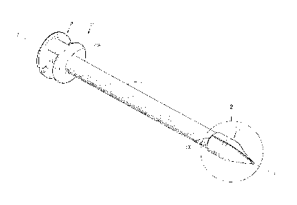
[0012] FIG. 1 is a perspective view of an obturator including a tip member
in
accordance with the present disclosure;
4b
CA 2817410 2019-06-10
CA 02817410 2013-06-03
10013] FIG. 2 is an enlarged view of the area of detail indentified in FIG.
1;
[0014] FIG, 3 is a bottom plan view of the obturator shown in FIG. I;
[0015] FIG. 4 is a side view of the obturator shown in FIG. 1;
[0016] FIG. 5 is a cross-sectional view taken along section line 5-5 of
FIG. 4;
[0017] FIG. 6 is a cross-sectional view taken along section line 6-6 of
FIG, 4;
[0018] FIG. 7 is a perspective view of the cross-section taken along
section line 6-6 of
FIG. 5;
[0019] FIG. 8 is a perspective view of a surgical access apparatus
according to the
present disclosure, including the obturator of FIG, I;
[0020] FIG, 9 is a cross-sectional view taken along section line 9-9 of
FIG. 8, shown
together with a cross-section of a layer of tissue and underlying body cavity;
[0021] FIG. I 0 is an enlarged view of the area of detail identified in
FIG. 9;
[0022] FIG. 11 is a cross-sectional view taken along section line 9-9 of
FIG. 8, shown
together with a cross-section of a layer of tissue and underlying insufflated
body cavity;
[0023] FIG. 12 is an enlarged perspective view of a tip member according to
an
alternative embodiment of the present disclosure; and
[0024] FIG. 13 is an enlarged perspective view of a tip member according to
another
alternative embodiment of the present disclosure.
[0025] The figures depict preferred embodiments of the present disclosure
for purposes
of illustration only. One skilled in the art will readily recognize from the
following discussion
that alternative embodiments of the structures and methods illustrated herein
may be employed
without departing from the principles of the present disclosure described
herein,
DETAILED DESCRIPTION
CA 02817410 2013-06-03
[0026] Embodiments of the presently disclosed surgical access apparatus for
use in
minimally invasive procedures are described in detail with reference to the
drawings, in which
like reference numerals designate identical or corresponding elements in each
of the several
views. As used herein, the term "distal" refers to that portion of the
apparatus which is farther
from the operator while the term "proximal" refers to that portion of the
apparatus which is
closer to the operator. The presently disclosed surgical access apparatus is
usable in an opening
through a patient's tissue, such as an incision or a naturally-occurring
orifice (e.g., mouth, anus,
or vagina),
[0027] Referring initially to FIG, 8, a surgical access apparatus 1000 is
shown. Surgical
access apparatus 1000 includes an obturator 100 insertable through a cannula
200, which will be
described further in detail below.
[0028] Referring now to FIG. I, obturator 100 includes an obturator shaft
102, a tip
member 110, and a handle 108, Obturator shaft 102 is an elongate member that
defines a
longitudinal axis "A", and has a proximal end 104 and a distal end 106. A
handle 108 is
mounted to the proximal end 104 of obturator shaft 102 and may include surface
features
suitable for grasping by an operator, e.g., an ergonomic grip incorporating
flanges, curves,
knurls, or the like.
[0029] Turning to FIG. 2, tip member 110, as shown, may have a tapered,
e.g., conical,
pyramidal, curved, etc., configuration that tapers to a distal tip 112. Distal
tip 112 may be blunt,
as shown, or may have another desirable atraumatic configuration, e.g.,
curvate, spheroid, or flat.
In other embodiments, distal tip 112 may be sharpened or pointed so as to be
configured to
penetrate tissue.
6
CA 02817410 2013-06-03
[0030] A channel 120 may be formed on an outer surface of the tip member
110.
Channel 120, as shown, is contoured to the outer surface of tip member 110 and
extends along
the length of tip member 110. Channel 120 includes an open proximal end 122
opposite an open
distal end 124. Distal end 124 may be coterminous with distal tip 112, or
distal tip 112 may
protrude past the distal end 124 of channel 120, as shown. Channel 120 is
defined by a pair of
opposed walls 126 joined by a channel floor 128. Channel 120 may have any
desirable
configuration, e.g., arcuate or U-shaped, or may be configured as a closed
member extending
along the tip member 110, e.g., a tube or box when viewed in cross-section.
Channel 120 defines
a path through which fluids, e.g., insufflation fluids, may flow. In further
embodiments, the
walls 126 or channel floor 128 may incorporate surface features such as
grooves or curves, e.g.,
to direct or alter fluid flow through channel 120, Tip member 110 may include
any number or
configuration of channels 120.
[0031] In some instances, the outer diameter of the obturator 100 may
closely match the
inner diameter of cannula 200. Thus, in some embodiments, channel 120 may
extend along the
entire length of obturator 100 or substantially the entire length of obturator
100. The channel
120 may be fluidly coupled directly to insufflation port 214 (FIG. 8).
[0032] Channel 120 may be formed on an outer surface of tip member 110 by,
e.g.,
cutting, etching, laser treatment, electrical arcing, and the like. In
embodiments, tip member 110
may be molded in a die or template such that channel 120 is pre-formed. Those
skilled in the art
of the present disclosure will envision other suitable methods of forming
channel 120.
[0033] Referring additionally to FIG. 3, channel 120, as shown, extends
radially inward
at a depth "D" along the outer surface of the tip member 110. Depth D, as
shown, may be a
constant dimension measured radially inward from an outer surface of the tip
member 110. In
7
CA 02817410 2013-06-03
this manner, channel floor 128 is disposed a depth D from the outer surface of
tip member 110 as
the channel 120 extends along the tapered profile of the tip member 110 toward
the distal tip
112. In embodiments, the depth D of channel 120 may vary along the
longitudinal length of the
tip member 110, e.g., the distance between the outer surface of the tip member
110 and the
channel floor 128 may increase or decrease along the longitudinal length of
tip member 110.
[00341 Referring now to FIGS. 4 and 5, tip member 110 is shown coupled with
obturator
shaft 102. Tip member 110 may be mounted to the distal end 106 of obturator
shaft 102 by any
suitable means, e.g., press-fit, threaded connection, bayonet-type coupling,
adhesion, or
ultrasonic welding. In embodiments, tip member 110 and obturator shaft 102 may
be integrally
formed. Additionally, tip member 110 may be overmolded about a pre-existing
tip member, or
one or more channels 120 may be formed on a pre-existing tip member in the
manner described
above. Accordingly, tip member 110 may he configured and dimensioned to be
retrofitted to a
number of existing devices and obturators,
100351 Referring additionally to FIGS. 6 and 7, the open proximal end 122
of channel
120 provides an entrance path to channel 120 as a fluid, e.g., insufflation
fluid, advances distally
along the obturator shaft 102 toward the tip member 110. Tip member 110, as
shown, may have
a hollow interior, or may be a solid member. In embodiments, tip member 110
may incorporate
a transparent region or optical window through which light may pass, allowing
for visualization
or iliumination outside the tip member 110 with an endoscope or other viewing
device (not
shown).
[0036] Turning now to FIGS. 8 and 9, the obturator 100 is configured for
insertion
through eannula 200. Cannula 200 includes a housing 210 and a cannula shaft
220 extending
distally from the housing 210. Housing 210 defines an interior annular recess
and includes a
8
CA 02817410 2013-06-03
proximal end 211 and a distal end 212 each defining an aperture configured to
accommodate
insertion of the obturator shaft 102 therethrough. Cannu la shaft 220 has an
open proximal and
221 opposite an open distal end 222, and defines an internal lumen 224
extending from the
proximal end 221 to the distal end 222. Lumen 224 is dimensioned to
accommodate passage of
the obturator shaft 102 and tip member 110 through the cannula shaft 220.
[0037] A seal member 218, as shown, may be disposed within housing 210.
Seal
member 218 may be press fit, adhered, welded, or otherwise secured within
housing 210. Seal
member 218 is configured to sealably engage obturator shaft 102, or an
instrument inserted
therethrough. Accordingly, seal member 218 may be configured as a septum,
conical, or disc
seal. In embodiments, seal member 218 may be configured as a zero-closure
seal, e.g., a
duckbill, and may be configured to inhibit the proximal migration of fluids
through cannula 200
in the absence of an instrument inserted therethrough. In further embodiments,
cannula 200 may
incorporate multiple seal members of varying configurations. Such seal members
may be
disposed in either or both the cannula housing 210 or cannula shaft 220.
[0038] Obturator 100, as shown, is insertable through lumen 224 of cannula
shaft 220.
Obturator 100 is dimensioned such that upon engagement of the handle 108 with
the proximal
end 211 of housing 210 of cannula 200, a portion of tip member 110 and channel
120 is exposed
distally of the cannula shaft 220. At least a portion of tip member 110
remains disposed within
lumen 224, as will be described further below.
[0039] Housing 210, as shown, includes an insufflation port 214 for
transmitting fluids,
e.g., insufflation fluids, therethrough. Insufflation port 214 may be
configured as a stopcock or
other suitable fluid port. Insufflation port 214 may be coupled with, e.g., a
source of insufflation
fluid or vacuum, or to a fluid line connected to a fluid source. Insufflation
port 214 may include
9
CA 02817410 2013-06-03
a valve 215 or fluid lock for selectively controlling the flow of fluids
through insufflation port
214,
[00401 A pair of tabs 216 extends radially outward from an outer surface of
the housing
210. Tabs 216 are suitable for grasping by an operator, e.g., the ring and
index finger of one
hand, Thus, tabs 216 provide an ergonomic grip such that an operator may grasp
tabs 216
together with the handle 108 of obturator 100 to facilitate translation of the
obturator 100 relative
to the cannula 200. In this manner, an operator may also move the entire
surgical access
apparatus 1000.
[0041] With continued reference to FIG. 9, the surgical access apparatus
1000, as shown,
is configured to be inserted through a layer of tissue "T÷. Tissue T defines a
body cavity "BC",
which may include underlying structures "S", such as tissue or body organs.
[00421 FIG, 10 illustrates an initial penetration or incision of tissue T.
An operator may
grasp handle 108 of obturator 100 and tabs 216 of cannula 200 (FIG. 8), and,
upon distal
movement of obturator 100, tip member 110 dilates and advances through tissue
T, creating a
path for cannula shaft 220 to be inserted through tissue T. Cannula shaft 220
may include one or
more visual indicator(s) to indicate the position of cannula 200 within the
tissue. For instance,
the visual indicator(s) may inform a user as to when the entire distal end 222
is within the
incision. Thus, the user would know that surgical access apparatus 1000 is in
a position where
insufflation gas would be effectively trapped by the tissue and retained
within the insufflation
channel 120
[0043] Insufflation fluids "F" are introduced through insufflation port 214
and into lumen
224 of cannula shaft 220. The presence of the obturator shaft 102 within lumen
224 defines an
annular space through which insufflation fluids F flow.
CA 02817410 2013-06-03
[0044] Seal member 218, as described above, inhibits the proximal migration
of
insufflation fluids F through the cannula shaft 220. Accordingly, pressurized
insufflation fluids
F entering eannula 200 through insufflation port 214 advance distally through
lumen 224 toward
tip member 110.
[0045] A proximal portion of channel 120, as shown, is disposed within and
in fluid
communication with lumen 224. With additional reference to FIG. 7, the
proximal end 122 of
channel 120 is exposed within the lumen 224 such that insufflation fluids F
may enter channel
120 and advance distally into body cavity BC, As pressurized fluids build up
within lumen 224,
channel 120 provides a path of least resistance along which pressurized
insufflation fluids F will
escape the higher-pressure environment within lumen 224, Accordingly,
controlling the rate of
flow through insufflation port 214 affects the fluid pressure within lumen 224
and the subsequent
flow of insufflation fluids F along channel 120 and into body cavity BC.
100461 In this manner, the supply of insufflation fluids F to body cavity
BC is achieved
directly through the carmula 200. The passage of insufflation fluids F along
an outer surface of
the tip member 110 of obturator 100 obviates the need for an additional
insufflation supply and
accompanying sealing structure for obturator 100, as will described in further
detail below.
f00471 The introduction of pressurized insufflation fluids F into body
cavity BC creates
an insufflated workspace such that tissue T may be lifted away from underlying
structures S
(FIG. 9). As shown in FIG. 10, the positioning of the distal end 124 of the
channel 120 at or near
the distal end of the tip member 110 enables insufflation fluids to begin to
be introduced into the
body cavity almost immediately upon the distal tip of the tip member
penetrating through the
abdominal wall, Accordingly, a larger working space is created for a minimally
invasive
procedure such that further advancement of the obturator 100 safely into body
cavity BC is
11
CA 02817410 2013-06-03
possible, facilitating, e.g., visualization or illumination of the body cavity
BC, or further dilation
of tissue T or structures S to reach a desired working site. Once the tissue,
e.g, the abdominal
wall, has been fully penetrated (see, e.g, F1G. 1), the obturator 100 may be
withdrawn from the
cannula 200, and another instrument (not shown) may be inserted through the
cannula 200. As
described above, the seal member 218 may be configured to maintain
insufflation fluids F within
body cavity BC in the absence of obturator 100 or another instrument.
[0048] Turning now to FIG. 12, an alternative embodiment of a tip member
according to
the present disclosure, designated tip member 310, is shown. Tip member 310
includes a
channel 320 that is substantially similar to channel 120 described above. Each
of side channels
322, 324 includes a proximal portion in parallel relation with channel 320,
and a distal portion
that curves toward and merges with channel 320 at an intersection 326 along
the surface of tip
member 310. Channel 320 and side channels 322, 324 are in fluid communication
such that
insufflation fluids F (FIG. 9) entering any of channel 320 or side channels
322, 324 will reach a
distal portion of channel 320 at intersection 326. Accordingly, insufflation
fluids F may be
supplied to a distal portion of channel 320 through any of side channels 322,
324, or directly
through a proximal portion of channel 320 to reach a body cavity BC (FIG. 9).
in this manner,
several paths are provided for insufflation fluids F to exit lumen 224 (FIG.
9) and reach body
cavity BC such that an obstruction of one path does not inhibit the
insufflation of body cavity
BC. In further embodiments, tip member 310 may include any number or
configuration of side
channels.
[0049] Turning now to FIG. 13, a further embodiment of a tip member
according to the
present disclosure, designated 410, is shown. Tip member 410 includes a
proximal end 412 and
a distal end defined by a distal tip 414. A channel 420 is formed on an outer
surface of the tip
12
CA 02817410 2013-06-03
member 410, and has a similar configuration to channel 120 described above,
Channel 420
includes an open proximal end 422 coincident with the proximal end 412 of tip
member 410, and
an open distal end 424. Channel 420 extends a portion of the longitudinal
length of tip member
410 such that the open distal end 424 of channel 420 is spaced proximally away
from the distal
tip 414 of tip member 410. Accordingly, the path defined by channel 420 is
contoured about a
portion of the outer surface of tip member 410, and insufflation fluids F
(FIG. 9) advancing
through channel 420 exit the open distal end 424 of channel 420 at a distance
longitudinally and
radially spaced away from the distal tip 414. In this manner, the flow profile
of insufflation
fluids F may be controlled, e.g., to reach outlying structures S (FIG. 9) or
to disperse insufflation
fluids F over a wider area,
[00501 The present invention may provide various advantages over
conventional
arrangements, such as the use of a veress needle to introduce insufflation
fluids. As shown in
FIG, 10, the positioning of the distal end 124 of the channel 120 at or near
the distal end of the
tip member 110 enables insufflation fluids to begin to be introduced into the
body cavity almost
immediately upon the distal tip 112 of the tip member 110 penetrating through
the abdominal
wall, By eliminating the use of a veress needle, this arrangement minimizes
the likelihood that
an injury to underlying anatomical structures will occur. The introduction of
pressurized
insufflation fluids F into body cavity BC in order to create an insufflated
workspace (which is
typically a requirement of laparoseopie surgeries such that tissue T may be
lifted away from
underlying structures S) is performed much more safely than with a
conventional veress needle.
[00511 Still further, the present invention may provide various advantages
over
conventional arrangements such as certain optical obturators. For example,
there exist optical
obturators that receive endoscopes therein; these optical obturators may
include holes along their
13
CA 02817410 2013-06-03
shafts or at their proximal ends for allowing insufflation fluid to enter the
hollow interior of the
optical obturator, as well as holes near the distal end thereof for expelling
the insufflation fluids
from the hollow interior and into a body cavity. While these distally located
holes may provide
for the flow of insufflation fluids, they are located more proximally relative
to its respective
distalmost tip than may be achieved by the positioning of the distal end 124
of the channel 120,
and thus the distalmost tip of these conventional optical obturators must be
inserted farther into a
body cavity in order for insufflation fluids to begin to flow into the body
cavity. By needing to
be inserted farther into a body cavity prior to insufflation fluids beginning
to flow into the body
cavity, these conventional optical obturators have a higher risk of
inadvertently damaging the
underlying anatomical structures.
[0052] in contrast, in various embodiments of the present invention, the
distal end 124 of
the channel 120 may be positioned at the distalmost end of the tip member 110.
This
arrangement enables insufflation fluids to begin to be introduced into the
body cavity almost
immediately upon the distal tip of the tip member penetrating through the
abdominal wall, and
earlier than would be possible in such above-described conventional optical
obturators. This
further reduces the likelihood that an injury to underlying anatomical
structures will occur and
further improves patient safety.
[0053] An additional advantage of the present invention as compared to
above-described
conventional optical obturators is that the provision of channels on the outer
surface of the tip
member may help avoid problems that are caused by the arrangements of the
conventional
optical obturators, e.g., that have holes that are in fluid communication with
the hollow interior
of the obturator. The above-described conventional optical obturators receive
endoscopes in
their hollow interiors, and thus having holes in the obturator walls as they
do requires that a seal
14
CA 02817410 2013-06-03
be provided in the interior of the obturator, e.g., at the proximal end
thereof; in order to prevent
the proximal flow and escape of insufflation gas between the interior wall of
the obturator and
the outer surface of the endoscope. This seal adds costs and complexity to the
manufacture of
this conventional optical obturator, as well as provides another potential
leak path during a
surgical procedure.
[00541 In contrast, the provision of channels on the outer surface of the
tip member, as
described hereinabove in connection with the present invention, avoids the
need for a seal in the
interior of the obturator. Since the channels are not in fluid communication
with the hollow
interior of the obturator, insufflation fluids that enter into the annular
space within the cannula do
not enter the interior of the obturator, and thus there is no possibility that
the insufflation fluids
will flow proximally and escape between the interior wall of the obturator and
the outer surface
of the endoscope. Rather, insufflation fluids flow only through the channel
120 and into the
body cavity, and an endoscope that is inserted within the optical obturator
need not be sealed
relative thereto.
[0055] A still further advantage of the present invention as compared to
the above-
described conventional optical obturators is that the provision of channels on
the outer surface of
the tip member may help avoid the need for other seals that are employed in
the above-described
conventional optical obturators. For example, these conventional optical
obturators may also
include a seal at the distal end of the cannula tube, this distal cannula seal
sealing between the
cannula tube and the outer surface of the obturator. Such a seal is typically
necessary such that
insufflation gas received via the cannula housing is directed first through
the holes in the optical
obturator and into the interior of the optical obturator and then out of the
interior through the
distalmost hole of the obturator. Without the distal cannula seal,
insufflation gas received via the
CA 02817410 2013-06-03
cannula housing would attempt to be expelled out of the distal end of the
cannula tube, between
the inner wall of the cannula tube and the outer surface of the obturator, but
would be prevented
from doing so because of the direct contact between the tip of the optical
member and the tissue.
Again, this distal cannula seal adds casts and complexity to the manufacture
of this conventional
optical obturator, as well as provides another potential leak path during a
surgical procedure.
[0056] In contrast, the provision of channels on the outer surface of the
tip member, as
described hereinabove in connection with the present invention, avoids the
need for this distal
cannula seal. In various embodiments of the present invention, insufflation
gas received via the
cannula housing is expelled out of the distal end of the cannula tube, between
the inner wall of
the cannula tube and the outer surface of the obturator. However, instead of
being prevented
from being expelled because of the direct contact between the tip of the
optical member and the
tissue (as is the case with the above-described conventional optical
obturators), the provision of
the channel or channels on the outer surface of the tip member provide a path
for such
insufflation gas to flow, and specifically a path to the distalinost tip of
the tip member so as to be
expelled into a body cavity immediately as the wall of the body cavity is
penetrated.
[0057] The present invention, according to various embodiments thereof, may
also
provide the advantage that it requires virtually no modifications of the
various components of a
trocar. As set forth above, not only must the above-described conventional
optical obturators
provide two additional seals (a first seal between the interior surface of the
optical obturator and
the endoscope; and a distal cannula seal between the interior surface of the
cannula tube and the
outer surface of the optical obturator), but almost all of the components of
this system arc
required to be re-designed as compared to an ordinary trocar in order to
accommodate these seals
and the desired flow of insufflation gas into the interior of the optical
obturator. In contrast,
16
CA 02817410 2013-06-03
every component of the system of the present invention save the tip member,
may ¨ if desired ¨
remain completely unchanged from an ordinary trocar, thereby saving costs and
enabling the
advantages of the present invention to be provided simply by providing a
channeled tip member
an an ordinary trocar system; without requiring modification of the remaining
components of the
trocar system.
[0058] It will be
understood that various modifications may be made to the embodiments
disclosed herein. Therefore, the above description should not be construed as
limiting, but
merely as exemplifications of embodiments. Those skilled in the art will
envision other
modifications within the scope and spirit of the present disclosure.
17